


ASTM B452-09(2015)
(Specification)Standard Specification for Copper-Clad Steel Wire for Electronic Application
Standard Specification for Copper-Clad Steel Wire for Electronic Application
ABSTRACT
This specification covers bare round copper-clad steel wire for electronic application. Four classes of copper-clad steel wire are covered as Class 30HS, 30A, 40HS, and 40A. The wire shall consist of a core of homogeneous open-hearth, electric-furnace, or basic-oxygen steel with a continuous outer cladding of copper thoroughly bonded to the core throughout. The copper-lad steel wire shall conform to the tensile strength and elongation requirements. Electrical resistivity test shall be performed at a specified temperature of each class of wire and shall not exceed the values prescribed in this specification. Dimensional measurements shall be made with a micrometer caliper and shall withstand torsion test without fracturing. Copper cladding to the steel of each of the four specimens shall conform to the adhesion criterion. Surface finish shall meet the required allowable number of defects.
SCOPE
1.1 This specification covers bare round copper-clad steel wire for electronic application.
1.2 Four classes of copper-clad steel wire are covered as follows:
1.2.1 Class 30HS—Nominal 30 % conductivity hard-drawn,
1.2.2 Class 30A—Nominal 30 % conductivity annealed,
1.2.3 Class 40HS—Nominal 40 % conductivity hard-drawn, and
1.2.4 Class 40A—Nominal 40 % conductivity annealed.
1.3 The values stated in inch-pound units are to be regarded as the standard. The values given in parentheses are in SI units.
General Information
Buy Standard

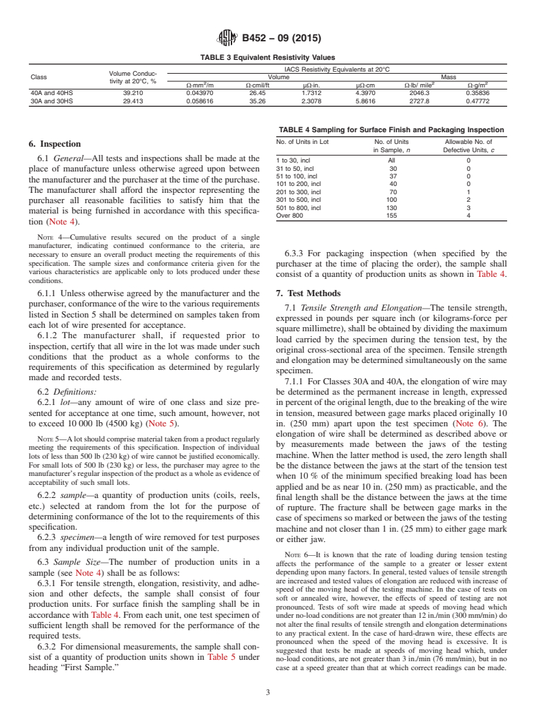


Standards Content (Sample)
NOTICE: This standard has either been superseded and replaced by a new version or withdrawn.
Contact ASTM International (www.astm.org) for the latest information
Designation:B452 −09 (Reapproved 2015)
Standard Specification for
Copper-Clad Steel Wire for Electronic Application
This standard is issued under the fixed designation B452; the number immediately following the designation indicates the year of
original adoption or, in the case of revision, the year of last revision. A number in parentheses indicates the year of last reapproval. A
superscript epsilon (´) indicates an editorial change since the last revision or reapproval.
This standard has been approved for use by agencies of the U.S. Department of Defense.
1. Scope 3.1.2 Wire size, diameter in inches (see 5.3 and Table 1),
3.1.3 Class of wire (see 1.2 and Table 1),
1.1 This specification covers bare round copper-clad steel
3.1.4 Packaging and shipping (Section 10),
wire for electronic application.
3.1.5 If inspection is required (see 6.3.3), and
1.2 Four classes of copper-clad steel wire are covered as
3.1.6 Place of inspection (see 6.1).
follows:
1.2.1 Class 30HS—Nominal 30 % conductivity hard-drawn,
4. Material
1.2.2 Class 30A—Nominal 30 % conductivity annealed,
4.1 The wire shall consist of a core of homogeneous
1.2.3 Class 40HS—Nominal 40 % conductivity hard-drawn,
open-hearth, electric-furnace, or basic-oxygen steel with a
and
continuous outer cladding of copper thoroughly bonded to the
1.2.4 Class 40A—Nominal 40 % conductivity annealed.
core throughout and shall be of such quality as to meet the
1.3 The values stated in inch-pound units are to be regarded
requirements of this specification (Note 1).
as the standard.The values given in parentheses are in SI units.
NOTE 1—The copper-clad steel wire provides a high-strength conductor
for use in wire and cable where greater strength is required and a lower
2. Referenced Documents
conductivity can be tolerated.At high frequencies the reduced conductiv-
ity is less pronounced due to concentration of the current in the outer
2.1 The following documents of the issue in effect on the
periphery of the wire. Minimum thickness of 6 % and 10 % of the radius
date of material purchase form a part of this specification to the
for 30 and 40 % conductivity material, respectively, has been established
extent referenced herein:
to facilitate the inspection of thickness on fine wires.
2.2 ASTM Standards:
5. General Requirements
B193 Test Method for Resistivity of Electrical Conductor
Materials
5.1 Tensile Strength and Elongation—The copper-clad steel
B258 Specification for Nominal Diameters and Cross-
wire shall conform to the tensile strength and elongation
SectionalAreasofAWGSizesofSolidRoundWiresUsed
requirements of Table 1. For intermediate sizes not listed in
as Electrical Conductors
Table 1, the elongation requirements of the next smaller size
2.3 National Institute of Standards and Technology: shall apply; in the case of tensile strength, the requirements of
NBS Handbook 100—Copper Wire Tables
the next larger size shall apply.
5.2 Resistivity—The electrical resistivity at a temperature of
3. Ordering Information
20°C shall not exceed the values prescribed in Table 2. See
3.1 Orders for material under this specification shall include
Note 2 for calculating electrical resistance.
the following information:
NOTE 2—Relationships which may be useful in connection with the
3.1.1 Quantity of each size and class,
values of electrical resistivity prescribed in this specification are shown in
Table 3. Resistivity units are based on the International Annealed Copper
Standard (IACS) adopted by IEC in 1913, which is ⁄58Ω·mm /m at 20°C
This specification is under the jurisdiction of ASTM Committee B01 on
for 100 % conductivity. The value of 0.017241Ω·mm /m and the value of
Electrical Conductors and is the direct responsibility of Subcommittee B01.06 on
0.15328 Ω·g/m at 20°C are respectively the international equivalent of
Bi-Metallic Conductors.
volume and weight resistivity of annealed copper equal to 100 %
Current edition approved April 1, 2015. Published April 2015. Originally
conductivity. The latter term means that a copper wire 1 in. in length and
approved in 1967. Last previous edition approved in 2009 as B452 – 09. DOI:
weighing 1 g would have a resistance of 0.15328Ω. This is equivalent to
10.1520/B0452-09R15.
2 a resistivity value of 875.20Ω· lb/mile , which signifies the resistance of
For referenced ASTM standards, visit the ASTM website, www.astm.org, or
a copper wire 1 mile in length weighing 1 lb. It is also equivalent, for
contact ASTM Customer Service at service@astm.org. For Annual Book of ASTM
example,to1.7241µΩ/cmoflengthofacopperbar1cm incrosssection.
Standards volume information, refer to the standard’s Document Summary page on
Acomplete discussion of this subject is contained in NBS Handbook 100.
the ASTM website.
Available from National Institute of Standards and Technology (NIST), 100 The use of five significant figures in expressing resistivity does not imply
Bureau Dr., Stop 1070, Gaithersburg, MD 20899-1070, http://www.nist.gov. the need for greater accuracy of measurement than that specified in Test
Copyright © ASTM International, 100 Barr Harbor Drive, PO Box C700, West Conshohocken, PA 19428-2959. United States
B452−09 (2015)
TABLE 1 Tensile and Elongation Requirements
Elongation, min.
Diameter Cross-Sectional Area at 20°C Tensile Strength, psi (kgf/mm ) %in10in.
(250 mm)
Class Class
2 2
in. mm cmil in. mm Class 30HS, min Class 30A, min Class 40HS, min Class 40A, min 30HS and 30A and
40HS 40A
0.0720 1.83 5180 0.00407 2.63 127 000 (89.3) 50 000 (35.2) 110 000 (77.3) 45 000 (31.6) 1.5 15
0.0641 1.63 4110 0.00323 2.08 127 000 (89.3) 50 000 (35.2) 110 000 (77.3) 45 000 (31.6) 1.5 15
0.0571 1.45 3260 0.00256 1.65 127 000 (89.3) 50 000 (35.2) 110 000 (77.3) 45 000 (31.6) 1.5 15
0.0508 1.29 2580 0.00203 1.31 127 000 (89.3) 50 000 (35.2) 110 000 (77.3) 45 000 (31.6) 1.5 15
0.0453 1.15 2050 0.00161 1.04 127 000 (89.3) 50 000 (35.2) 110 000 (77.3) 45 000 (31.6) 1.5 15
0.0403 1.02 1620 0.00128 0.823 127 000 (89.3) 50 000 (35.2) 110 000 (77.3) 45 000 (31.6) 1.0 15
0.0359 0.912 1290 0.00101 0.653 127 000 (89.3) 50 000 (35.2) 110 000 (77.3) 45 000 (31.6) 1.0 15
0.0320 0.813 1020 0.000804 0.519 127 000 (89.3) 50 000 (35.2) 110 000 (77.3) 45 000 (31.6) 1.0 15
0.0285 0.724 812 0.000638 0.412 127 000 (89.3) 55 000 (38.7) 110 000 (77.3) 50 000 (35.2) 1.0 15
0.0253 0.643 640 0.000503 0.324 127 000 (89.3) 55 000 (38.7) 110 000 (77.3) 50 000 (35.2) 1.0 15
0.0226 0.574 511 0.000401 0.259 127 000 (89.3) 55 000 (38.7) 110 000 (77.3) 50 000 (35.2) 1.0 15
0.0201 0.511 404 0.00317 0.205 127 000 (89.3) 55 000 (38.7) 110 000 (77.3) 50 000 (35.2) 1.0 10
0.0179 0.455 320 0.000252 0.162 127 000 (89.3) 55 000 (38.7) 110 000 (77.3) 50 000 (35.2) 1.0 10
0.0159 0.404 253 0.000199 0.128 127 000 (89.3) 55 000 (38.7) 110 000 (77.3) 50 000 (35.2) 1.0 10
0.0142 0.361 202 0.000158 0.102 127 000 (89.3) 55 000 (38.7) 110 000 (77.3) 50 000 (35.2) 1.0 10
0.0126 0.320 159 0.000125 0.0804 127 000 (89.3) 55 000 (38.7) 110 000 (77.3) 50 000 (35.2) 1.0 10
0.0113 0.287 128 0.000100 0.0647 127 000 (89.3) 55 000 (38.7) 110 000 (77.3) 50 000 (35.2) 1.0 10
0.0100 0.254 100 0.0000785 0.0507 127 000 (89.3) 55 000 (38.7) 110 000 (77.3) 50 000 (35.2) 1.0 10
0.0089 0.226 79.2 0.0000622 0.0401 127 000 (89.3) 55 000 (38.7) 110 000 (77.3) 50 000 (35.2) 1.0 10
0.0080 0.203 64.0 0.0000503 0.0324 127 000 (89.3) 55 000 (38.7) 110 000 (77.3) 50 000 (35.2) 1.0 10
0.0071 0.180 50.4 0.0000396 0.0255 127 000 (89.3) 55 000 (38.7) 110 000 (77.3) 50 000 (35.2) 1.0 10
0.0063 0.160 39.7 0.0000312 0.0201 127 000 (89.3) 55 000 (38.7) 110 000 (77.3) 50 000 (35.2) 1.0 10
0.0056 0.142 31.4 0.0000246 0.0159 127 000 (89.3) 55 000 (38.7) 110 000 (77.3) 50 000 (35.2) 1.0 10
0.0050 0.127 25.0 0.0000196 0.0127 127 000 (89.3) 55 000 (38.7) 110 000 (77.3) 50 000 (35.2) 1.0 10
0.0045 0.114 20.2 0.0000159 0.0103 127 000 (89.3) 55 000 (38.7) 110 000 (77.3) 50 000 (35.2) 1.0 10
0.0040 0.102 16.0 0.0000126 0.00811 127 000 (89.3) 55 000 (38.7) 110 000 (77.3) 50 000 (35.2) 1.0 10
0.0035 0.089 12.2 0.00000962 0.00621 127 000 (89.3) 55 000 (38.7) 110 000 (77.3) 50 000 (35.2) 1.0 10
0.0031 0.079 9.61 0.00000755 0.00487 127 000 (89.3) 55 000 (38.7) 110 000 (77.3) 50 000 (35.2) 1.0 10
TABLE 2 Resistivity, max, at 20°C
5.4 Adhesion and Other Defects—The copper-clad steel
Class of Wire Ω·mm /m wire, when tested in accordance with 7.4, shall not reveal any
30HS and 30A 0.05862 (0.058616)
seams, pits, slivers, or other imperfection of sufficient magni-
40HS and 40A 0.04397 (0.043970)
tude to indicate inherent defects or imperfections. Examination
ofthewireatthebreakwiththeunaidedeye(normalspectacles
excepted) shall show no separation of copper from the steel.
5.5 Joints—Necessary joints in the wire and rods prior to
Method B193. The use of five significant figures is required for complete
final drawing shall be made in accordance with good commer-
reversible conversion from one set of resistivity units to another.
cialpractice.Thefinishedwireshallcontainnojointsorsplices
5.3 Dimensions and Permissible Variations—The wire sizes
made at finished size.
shall be expressed as the diameter of the wire in decimal
5.6 Finish—The wire shall be free from copper discontinui-
fractions of an inch to the nearest 0.0001 in. (0.003 mm) (Note
ties and all imperfections not consistent with good commercial
3). For diameters under 0.0100 in. (0.254 mm), the wire shall
practice (see 7.5).
not vary from the specified diameter by more than 60.0001 in.
(0.003 mm) and for diameters of 0.0100 in. (0.254 mm) and
5.7 Copper Thickness—The average copper thickness must
over, the wire shall not vary from the specified diameter by
be sufficient to meet the maximum resistivity values stated in
more than 61 %, expressed to the nearest 0.0001 in. (0.003
Table 2. The minimum copper thickness at any point around
mm).
the circumference shall be not less than the following:
5.7.1 The 30 % conductivity wire shall have a minimum
NOTE 3—The values of the wire diameters in Table 1 are given to the
nearest 0.0001 in. (0.003 mm) and correspond to the standard sizes given
thickness of not less than 6 % of the wire radius.
inSpecificationB258.Theuseofgagenumberstospecifywiresizesisnot
5.7.2 The 40 % conductivity wire shall have a minimum
recognized in this specification because of the possibility of confusion.An
thickness of not less than 10 % of the wire radius (see 7.6 and
excellentdiscussionofwiregagesandrelatedsubjectsiscontainedin NBS
Handbook 100. Note 3).
B452−09 (2015)
TABLE 3 Equivalent Resistivity Values
IACS Resistivity Equivalents at 20°C
Volume Conduc-
Class Volume Mass
tivity at 20°C, %
2 2 2
Ω·mm /m Ω·cmil/ft µΩ·in. µΩ·cm Ω·lb/ mile Ω·g/m
40A and 40HS 39.210 0.043970 26.45 1.7312 4.3970 2046.3 0.35836
30A and 30HS 29.413 0.058616 35.26 2.3078 5.8616 2727.8 0.47772
TABLE 4 Sampling for Surface Finish and Packaging Inspection
No. of Units in Lot No. of Units Allowable No. of
6. Inspection
in Sample, n Defective Units, c
6.1 General—All tests and inspections shall be made at the
1 to 30, incl All 0
31 to 50, incl 30 0
place of manufacture unless otherwise agreed upon between
51 to 100, incl 37 0
the manufacturer and the purchaser at the time of the purchase.
101 to 200, incl 40 0
The manufacturer shall afford the inspector representing the
201 to 300, incl 70 1
301 to 500, incl 100 2
purchaser all reasonable facilities to satisfy him that the
501 to 800, incl 130 3
material is being furnished in accordance with this specifica-
Over 800 155 4
tion (Note 4).
NOTE 4—Cumulative results secured on the product of a single
manufacturer, indicating continued conformance to the criteria, are
6.3.3 For packaging inspection (when specified by the
necessary to ensure an overall product meeting the requirements of this
specification. The sample sizes and conformance criteria given for the
purchaser at the time of placing the order), the sample shall
various characteristics are applicable only to lots produced under these
consist of a quantity of production units as shown in Table 4.
conditions.
7. Test Methods
6.1.1 Unless otherwise agreed by the manufacturer and the
purchaser, conformance of the wire to the various requirements
7.1 Tensile Strength and Elongation—The tensile strength,
listed in Section 5 shall be determined on samples taken from
expressed in pounds per square inch (or kilograms-force per
each lot of wire presented for acceptance.
square millimetre), shall be obtained by dividing the maximum
6.1.2 The manufacturer shall, if requested prior to
load carried by the specimen during the tension test, by the
inspection, certify that all wire in the lot was made under such
original cross-sectional area of the specimen. Tensile strength
conditions that the product as a whole conforms to the
and elongation may be determined simultaneously on the same
requirements of this specification as determined by regularly
specimen.
made and recorded tests.
7.1.1 For Classes 30Aand 40A, the elongation of wire may
6.2 Definitions: be determined as the permanent increase in length, expressed
6.2.1 lot—any amount of wire of one class and size pre- inpercentoftheoriginallength,duetothebreakingofthewire
sented for acceptance at one time, such amount, however, not in tension, measured between gage marks placed originally 10
to exceed 10 000 lb (4500 kg) (Note 5). in. (250 mm) apart upon the test specimen (Note 6). The
elongation of wire shall be determined as described above or
NOTE 5—Alot should comprise material taken from a product regularly
by measurements made between the jaws of the testing
meeting the requirements of this specification. Inspection of individual
machine. When the latter method is used, the zero length shall
lots of less than 500 lb (230 kg) of wire cannot be justified economically.
For small lots of 500 lb (230 kg) or less, the purchaser may agree to the
be the distance between the jaws at the start of the tension test
manufacturer’s regular inspection of the product as a whole as evidence of
when 10 % of the minimum specified breaking load has been
acceptability of such small lots.
applied and be as near 10 in. (250 mm) as practicable, and the
6.2.2 sample—a quantity of production units (coils, reels,
final length shall be the distance between the jaws at the time
etc.) selected at random from the lot for the purpose of
of rupture. The fracture shall be between gage marks in the
determining conformance of the lot to the requirements of this
case of specimens so marked or between the jaws of the testing
specification.
machine and not closer than 1 in. (25 mm) to either gage mark
6.2.3 specimen—a length of wire removed for test purposes
or either jaw.
from any individual production unit of the sample.
NOTE 6—It is known
...
This document is not an ASTM standard and is intended only to provide the user of an ASTM standard an indication of what changes have been made to the previous version. Because
it may not be technically possible to adequately depict all changes accurately, ASTM recommends that users consult prior editions as appropriate. In all cases only the current version
of the standard as published by ASTM is to be considered the official document.
Designation: B452 − 09 B452 − 09 (Reapproved 2015)
Standard Specification for
Copper-Clad Steel Wire for Electronic Application
This standard is issued under the fixed designation B452; the number immediately following the designation indicates the year of
original adoption or, in the case of revision, the year of last revision. A number in parentheses indicates the year of last reapproval. A
superscript epsilon (´) indicates an editorial change since the last revision or reapproval.
This standard has been approved for use by agencies of the U.S. Department of Defense.
1. Scope
1.1 This specification covers bare round copper-clad steel wire for electronic application.
1.2 Four classes of copper-clad steel wire are covered as follows:
1.2.1 Class 30HS—Nominal 30 % conductivity hard-drawn,
1.2.2 Class 30A—Nominal 30 % conductivity annealed,
1.2.3 Class 40HS—Nominal 40 % conductivity hard-drawn, and
1.2.4 Class 40A—Nominal 40 % conductivity annealed.
1.3 The values stated in inch-pound units are to be regarded as the standard. The values given in parentheses are in SI units.
2. Referenced Documents
2.1 The following documents of the issue in effect on the date of material purchase form a part of this specification to the extent
referenced herein:
2.2 ASTM Standards:
B193 Test Method for Resistivity of Electrical Conductor Materials
B258 Specification for Nominal Diameters and Cross-Sectional Areas of AWG Sizes of Solid Round Wires Used as Electrical
Conductors
2.3 National Institute of Standards and Technology:
NBS Handbook 100—Copper Wire Tables
3. Ordering Information
3.1 Orders for material under this specification shall include the following information:
3.1.1 Quantity of each size and class,
3.1.2 Wire size, diameter in inches (see 5.3 and Table 1),
3.1.3 Class of wire (see 1.2 and Table 1),
3.1.4 Packaging and shipping (Section 10),
3.1.5 If inspection is required (see 6.3.3), and
3.1.6 Place of inspection (see 6.1).
4. Material
4.1 The wire shall consist of a core of homogeneous open-hearth, electric-furnace, or basic-oxygen steel with a continuous outer
cladding of copper thoroughly bonded to the core throughout and shall be of such quality as to meet the requirements of this
specification (Note 1).
NOTE 1—The copper-clad steel wire provides a high-strength conductor for use in wire and cable where greater strength is required and a lower
conductivity can be tolerated. At high frequencies the reduced conductivity is less pronounced due to concentration of the current in the outer periphery
This specification is under the jurisdiction of ASTM Committee B01 on Electrical Conductors and is the direct responsibility of Subcommittee B01.06 on Composite
Conductors.
Current edition approved Oct. 1, 2009April 1, 2015. Published November 2009April 2015. Originally approved in 1967. Last previous edition approved in 20022009 as
B452 – 02.B452 – 09. DOI: 10.1520/B0452-09.10.1520/B0452-09R15.
For referenced ASTM standards, visit the ASTM website, www.astm.org, or contact ASTM Customer Service at service@astm.org. For Annual Book of ASTM Standards
volume information, refer to the standard’sstandard’s Document Summary page on the ASTM website.
Available from National Institute of Standards and Technology (NIST), 100 Bureau Dr., Stop 1070, Gaithersburg, MD 20899-1070, http://www.nist.gov.
Copyright © ASTM International, 100 Barr Harbor Drive, PO Box C700, West Conshohocken, PA 19428-2959. United States
B452 − 09 (2015)
TABLE 1 Tensile and Elongation Requirements
Elongation, min.
Diameter Cross-Sectional Area at 20°C Tensile Strength, psi (kgf/mm ) % in 10 in.
(250 mm)
Class Class
2 2
in. mm cmil in. mm Class 30HS, min Class 30A, min Class 40HS, min Class 40A, min 30HS and 30A and
40HS 40A
0.0720 1.83 5180 0.00407 2.63 127 000 (89.3) 50 000 (35.2) 110 000 (77.3) 45 000 (31.6) 1.5 15
0.0641 1.63 4110 0.00323 2.08 127 000 (89.3) 50 000 (35.2) 110 000 (77.3) 45 000 (31.6) 1.5 15
0.0571 1.45 3260 0.00256 1.65 127 000 (89.3) 50 000 (35.2) 110 000 (77.3) 45 000 (31.6) 1.5 15
0.0508 1.29 2580 0.00203 1.31 127 000 (89.3) 50 000 (35.2) 110 000 (77.3) 45 000 (31.6) 1.5 15
0.0453 1.15 2050 0.00161 1.04 127 000 (89.3) 50 000 (35.2) 110 000 (77.3) 45 000 (31.6) 1.5 15
0.0403 1.02 1620 0.00128 0.823 127 000 (89.3) 50 000 (35.2) 110 000 (77.3) 45 000 (31.6) 1.0 15
0.0359 0.912 1290 0.00101 0.653 127 000 (89.3) 50 000 (35.2) 110 000 (77.3) 45 000 (31.6) 1.0 15
0.0320 0.813 1020 0.000804 0.519 127 000 (89.3) 50 000 (35.2) 110 000 (77.3) 45 000 (31.6) 1.0 15
0.0285 0.724 812 0.000638 0.412 127 000 (89.3) 55 000 (38.7) 110 000 (77.3) 50 000 (35.2) 1.0 15
0.0253 0.643 640 0.000503 0.324 127 000 (89.3) 55 000 (38.7) 110 000 (77.3) 50 000 (35.2) 1.0 15
0.0226 0.574 511 0.000401 0.259 127 000 (89.3) 55 000 (38.7) 110 000 (77.3) 50 000 (35.2) 1.0 15
0.0201 0.511 404 0.00317 0.205 127 000 (89.3) 55 000 (38.7) 110 000 (77.3) 50 000 (35.2) 1.0 10
0.0179 0.455 320 0.000252 0.162 127 000 (89.3) 55 000 (38.7) 110 000 (77.3) 50 000 (35.2) 1.0 10
0.0159 0.404 253 0.000199 0.128 127 000 (89.3) 55 000 (38.7) 110 000 (77.3) 50 000 (35.2) 1.0 10
0.0142 0.361 202 0.000158 0.102 127 000 (89.3) 55 000 (38.7) 110 000 (77.3) 50 000 (35.2) 1.0 10
0.0126 0.320 159 0.000125 0.0804 127 000 (89.3) 55 000 (38.7) 110 000 (77.3) 50 000 (35.2) 1.0 10
0.0113 0.287 128 0.000100 0.0647 127 000 (89.3) 55 000 (38.7) 110 000 (77.3) 50 000 (35.2) 1.0 10
0.0100 0.254 100 0.0000785 0.0507 127 000 (89.3) 55 000 (38.7) 110 000 (77.3) 50 000 (35.2) 1.0 10
0.0089 0.226 79.2 0.0000622 0.0401 127 000 (89.3) 55 000 (38.7) 110 000 (77.3) 50 000 (35.2) 1.0 10
0.0080 0.203 64.0 0.0000503 0.0324 127 000 (89.3) 55 000 (38.7) 110 000 (77.3) 50 000 (35.2) 1.0 10
0.0071 0.180 50.4 0.0000396 0.0255 127 000 (89.3) 55 000 (38.7) 110 000 (77.3) 50 000 (35.2) 1.0 10
0.0063 0.160 39.7 0.0000312 0.0201 127 000 (89.3) 55 000 (38.7) 110 000 (77.3) 50 000 (35.2) 1.0 10
0.0056 0.142 31.4 0.0000246 0.0159 127 000 (89.3) 55 000 (38.7) 110 000 (77.3) 50 000 (35.2) 1.0 10
0.0050 0.127 25.0 0.0000196 0.0127 127 000 (89.3) 55 000 (38.7) 110 000 (77.3) 50 000 (35.2) 1.0 10
0.0045 0.114 20.2 0.0000159 0.0103 127 000 (89.3) 55 000 (38.7) 110 000 (77.3) 50 000 (35.2) 1.0 10
0.0040 0.102 16.0 0.0000126 0.00811 127 000 (89.3) 55 000 (38.7) 110 000 (77.3) 50 000 (35.2) 1.0 10
0.0035 0.089 12.2 0.00000962 0.00621 127 000 (89.3) 55 000 (38.7) 110 000 (77.3) 50 000 (35.2) 1.0 10
0.0031 0.079 9.61 0.00000755 0.00487 127 000 (89.3) 55 000 (38.7) 110 000 (77.3) 50 000 (35.2) 1.0 10
of the wire. Minimum thickness of 6 % and 10 % of the radius for 30 and 40 % conductivity material, respectively, has been established to facilitate the
inspection of thickness on fine wires.
5. General Requirements
5.1 Tensile Strength and Elongation—The copper-clad steel wire shall conform to the tensile strength and elongation
requirements of Table 1. For intermediate sizes not listed in Table 1, the elongation requirements of the next smaller size shall
apply; in the case of tensile strength, the requirements of the next larger size shall apply.
5.2 Resistivity—The electrical resistivity at a temperature of 20°C shall not exceed the values prescribed in Table 2. See Note
2 for calculating electrical resistance.
NOTE 2—Relationships which may be useful in connection with the values of electrical resistivity prescribed in this specification are shown in Table
3. Resistivity units are based on the International Annealed Copper Standard (IACS) adopted by IEC in 1913, which is ⁄58 Ω·mm /m at 20°C for 100 %
2 2
conductivity. The value of 0.017241 Ω·mm /m and the value of 0.15328 Ω·g/m at 20°C are respectively the international equivalent of volume and
weight resistivity of annealed copper equal to 100 % conductivity. The latter term means that a copper wire 1 in. in length and weighing 1 g would have
a resistance of 0.15328 Ω. This is equivalent to a resistivity value of 875.20Ω· lb/mile , which signifies the resistance of a copper wire 1 mile in length
weighing 1 lb. It is also equivalent, for example, to 1.7241 μΩ/cm of length of a copper bar 1 cm in cross section. A complete discussion of this subject
is contained in NBS Handbook 100. The use of five significant figures in expressing resistivity does not imply the need for greater accuracy of
measurement than that specified in Test Method B193. The use of five significant figures is required for complete reversible conversion from one set of
resistivity units to another.
TABLE 2 Resistivity, max, at 20°C
Class of Wire Ω·mm /m
Class of Wire Ω·mm /m
30HS and 30A 0.05862 (0.058616)
40HS and 40A 0.04397 (0.043970)
B452 − 09 (2015)
TABLE 3 Equivalent Resistivity Values
IACS Resistivity Equivalents at 20°C
Volume Conduc-
Class Volume Mass
tivity at 20°C, %
2 2 2
Ω·mm /m Ω·cmil/ft μΩ·in. μΩ·cm Ω·lb/ mile Ω·g/m
40A and 40HS 39.210 0.043970 26.45 1.7312 4.3970 2046.3 0.35836
30A and 30HS 29.413 0.058616 35.26 2.3078 5.8616 2727.8 0.47772
5.3 Dimensions and Permissible Variations—The wire sizes shall be expressed as the diameter of the wire in decimal fractions
of an inch to the nearest 0.0001 in. (0.003 mm) (Note 3). For diameters under 0.0100 in. (0.254 mm), the wire shall not vary from
the specified diameter by more than 60.0001 in. (0.003 mm) and for diameters of 0.0100 in. (0.254 mm) and over, the wire shall
not vary from the specified diameter by more than 61 %, expressed to the nearest 0.0001 in. (0.003 mm).
NOTE 3—The values of the wire diameters in Table 1 are given to the nearest 0.0001 in. (0.003 mm) and correspond to the standard sizes given in
Specification B258. The use of gage numbers to specify wire sizes is not recognized in this specification because of the possibility of confusion. An
excellent discussion of wire gages and related subjects is contained in NBS Handbook 100.
5.4 Adhesion and Other Defects—The copper-clad steel wire, when tested in accordance with 7.4, shall not reveal any seams,
pits, slivers, or other imperfection of sufficient magnitude to indicate inherent defects or imperfections. Examination of the wire
at the break with the unaided eye (normal spectacles excepted) shall show no separation of copper from the steel.
5.5 Joints—Necessary joints in the wire and rods prior to final drawing shall be made in accordance with good commercial
practice. The finished wire shall contain no joints or splices made at finished size.
5.6 Finish—The wire shall be free from copper discontinuities and all imperfections not consistent with good commercial
practice (see 7.5).
5.7 Copper Thickness—The average copper thickness must be sufficient to meet the maximum resistivity values stated in Table
2Table 2. . The minimum copper thickness at any point around the circumference shall be not less than the following:
5.7.1 The 30 % conductivity wire shall have a minimum thickness of not less than 6 % of the wire radius.
5.7.2 The 40 % conductivity wire shall have a minimum thickness of not less than 10 % of the wire radius (see 7.6 and Note
3).
6. Inspection
6.1 General—All tests and inspections shall be made at the place of manufacture unless otherwise agreed upon between the
manufacturer and the purchaser at the time of the purchase. The manufacturer shall afford the inspector representing the purchaser
all reasonable facilities to satisfy him that the material is being furnished in accordance with this specification (Note 4).
NOTE 4—Cumulative results secured on the product of a single manufacturer, indicating continued conformance to the criteria, are necessary to ensure
an overall product meeting the requirements of this specification. The sample sizes and conformance criteria given for the various characteristics are
applicable only to lots produced under these conditions.
6.1.1 Unless otherwise agreed by the manufacturer and the purchaser, conformance of the wire to the various requirements listed
in Section 5 shall be determined on samples taken from each lot of wire presented for acceptance.
6.1.2 The manufacturer shall, if requested prior to inspection, certify that all wire in the lot was made under such conditions
that the product as a whole conforms to the requirements of this specification as determined by regularly made and recorded tests.
6.2 Definitions:
6.2.1 lot—any amount of wire of one class and size presented for acceptance at one time, such amount, however, not to exceed
10 000 lb (4500 kg) (Note 5).
NOTE 5—A lot should comprise material taken from a product regularly meeting the requirements of this specification. Inspection of individual lots
of less than 500 lb (230 kg) of wire cannot be justified economically. For small lots of 500 lb (230 kg) or less, the purchaser may agree to the
manufacturer’s regular inspection of the product as a whole as evidence of acceptability of such small lots.
6.2.2 sample—a quantity of production units (coils, reels, etc.) selected at random from the lot for the purpose of determining
conformance of the lot to the requirements of this specification.
6.2.3 specimen—a length of wire removed for test purposes from any individual production unit of the sample.
6.3 Sample Size—The number of production units in a sample (see Note 4) shall be as follows:
6.3.1 For tensile strength, elongation, resistivity, and adhesion and other defects, the sample shall consist of four production
units. For surface finish the sampling shall be in accordance with Table 4. From each unit, one test specimen of sufficient length
shall be removed for the performance of the required tests.
6.3.2 For dimensional measurements, the sample shall consist of a quantity of production units shown in Table 5 under heading
“First Sample.”
6.3.3 For packaging inspection (when specified by the purchaser at the time of placing the order), the sample shall consist of
a quantity of production units as shown in Table 4.
B452 − 09 (2015)
TABLE 4 Sampling for Surface Finish and Packaging Inspection
No. of Units in Lot No. of Units Allowable No. of
in Sample, n Defective Units, c
1 to 30, incl All 0
31 to 50, incl 30 0
51 to 100, incl 37 0
101 to 200, incl 40 0
201 to 300, incl 70 1
301 to 500, incl 100 2
501 to 800, incl 130 3
Over 800 155 4
7. Test Methods
7.1 Tensile Strength and Elongation—The tensile strength, expressed in pounds per square inch (or kilograms-force per square
millimetre), shall be obtained by dividing the maximum load carried by the specimen during the te
...
Questions, Comments and Discussion
Ask us and Technical Secretary will try to provide an answer. You can facilitate discussion about the standard in here.