


ASTM D3803-91(2014)
(Test Method)Standard Test Method for Nuclear-Grade Activated Carbon
Standard Test Method for Nuclear-Grade Activated Carbon
SIGNIFICANCE AND USE
5.1 The results of this test method give a conservative estimate of the performance of nuclear-grade activated carbon used in all nuclear power plant HVAC systems for the removal of radioiodine.
SCOPE
1.1 This test method is a very stringent procedure for establishing the capability of new and used activated carbon to remove radio-labeled methyl iodide from air and gas streams. The single test method described is for application to both new and used carbons, and should give test results comparable to those obtained from similar tests required and performed throughout the world. The conditions employed were selected to approximate operating or accident conditions of a nuclear reactor which would severely reduce the performance of activated carbons. Increasing the temperature at which this test is performed generally increases the removal efficiency of the carbon by increasing the rate of chemical and physical absorption and isotopic exchange, that is, increasing the kinetics of the radioiodine removal mechanisms. Decreasing the relative humidity of the test generally increases the efficiency of methyl iodide removal by activated carbon. The water vapor competes with the methyl iodide for adsorption sites on the carbon, and as the amount of water vapor decreases with lower specified relative humidities, the easier it is for the methyl iodide to be adsorbed. Therefore, this test method is a very stringent test of nuclear-grade activated carbon because of the low temperature and high relative humidity specified. This test method is recommended for the qualification of new carbons and the quantification of the degradation of used carbons.
1.1.1 Guidance for testing new and used carbons using conditions different from this test method is offered in Annex A1.
1.2 The values stated in SI units are to be regarded as standard. No other units of measurement are included in this standard.
1.3 This standard does not purport to address all of the safety concerns, if any, associated with its use. It is the responsibility of the user of this standard to establish appropriate safety and health practices and determine the applicability of regulatory limitations prior to use.
General Information
Buy Standard
Standards Content (Sample)
NOTICE: This standard has either been superseded and replaced by a new version or withdrawn.
Contact ASTM International (www.astm.org) for the latest information
Designation: D3803 − 91 (Reapproved 2014)
Standard Test Method for
Nuclear-Grade Activated Carbon
This standard is issued under the fixed designation D3803; the number immediately following the designation indicates the year of
original adoption or, in the case of revision, the year of last revision.Anumber in parentheses indicates the year of last reapproval.A
superscript epsilon (´) indicates an editorial change since the last revision or reapproval.
1. Scope 2. Referenced Documents
1.1 This test method is a very stringent procedure for 2.1 ASTM Standards:
establishing the capability of new and used activated carbon to D1193Specification for Reagent Water
D2652Terminology Relating to Activated Carbon
remove radio-labeled methyl iodide from air and gas streams.
Thesingletestmethoddescribedisforapplicationtobothnew D2854Test Method for Apparent Density of Activated
Carbon
and used carbons, and should give test results comparable to
those obtained from similar tests required and performed E300Practice for Sampling Industrial Chemicals
E691Practice for Conducting an Interlaboratory Study to
throughout the world. The conditions employed were selected
to approximate operating or accident conditions of a nuclear Determine the Precision of a Test Method
2.2 Code of Federal Regulations:
reactor which would severely reduce the performance of
activatedcarbons.Increasingthetemperatureatwhichthistest CFR Title 49,Section 173.34, “Qualification, Maintenance,
is performed generally increases the removal efficiency of the and Use of Cylinders’’
carbon by increasing the rate of chemical and physical absorp- CFR Title 49,Part 178, Subpart C, “Specifications for
tion and isotopic exchange, that is, increasing the kinetics of Cylinders’’
the radioiodine removal mechanisms. Decreasing the relative 2.3 Military Standards:
humidityofthetestgenerallyincreasestheefficiencyofmethyl MIL-F-51068D Filter, Particulate High Efficiency, Fire
iodideremovalbyactivatedcarbon.Thewatervaporcompetes Resistant
with the methyl iodide for adsorption sites on the carbon, and MIL-F-51079A Filter, Medium Fire Resistant, High Effi-
as the amount of water vapor decreases with lower specified ciency
relative humidities, the easier it is for the methyl iodide to be MIL-STD-45662 Calibration Systems Requirements
adsorbed.Therefore, this test method is a very stringent test of 2.4 Other Standards:
nuclear-grade activated carbon because of the low temperature ANSI/ASME N45.2.6 Qualifications of Inspection,
Examination, and Testing Personnel for Nuclear Power
and high relative humidity specified. This test method is
recommended for the qualification of new carbons and the Plants
quantification of the degradation of used carbons.
3. Terminology
1.1.1 Guidance for testing new and used carbons using
3.1 Definitions of Terms Specific to This Standard:
conditions different from this test method is offered in Annex
3.1.1 counter effıciency (CE)—the fraction of the actual
A1.
number of disintegrations of a radioactive sample that is
1.2 The values stated in SI units are to be regarded as
recorded by a nuclear counter.
standard. No other units of measurement are included in this
3.1.2 effıciency (E)—the percentage of the contaminant
standard.
removed from a gas stream by an adsorption bed; expressed
1.3 This standard does not purport to address all of the
mathematically as E = 100 − P, where E and P are given in
safety concerns, if any, associated with its use. It is the
percent.
responsibility of the user of this standard to establish appro-
priate safety and health practices and determine the applica-
For referenced ASTM standards, visit the ASTM website, www.astm.org, or
bility of regulatory limitations prior to use.
contact ASTM Customer Service at service@astm.org. For Annual Book of ASTM
Standards volume information, refer to the standard’s Document Summary page on
the ASTM website.
Published by the General Service Administration, 18th and “F”’ St., N. W.,
This test method is under the jurisdiction of ASTM Committee D28 on Washington, DC 20405.
Activated Carbon and is the direct responsibility of Subcommittee D28.04 on Gas Available from Standardization Documents Order Desk, DODSSP, Bldg. 4,
Phase Evaluation Tests. Section D, 700 Robbins Ave., Philadelphia, PA 19111-5098, http://
Current edition approved July 1, 2014. Published September 2014. Originally dodssp.daps.dla.mil.
approved in 1979. Last previous edition approved in 2009 as D3803–91 (2009). Available fromAmerican National Standards Institute (ANSI), 25 W. 43rd St.,
DOI: 10.1520/D3803-91R14. 4th Floor, New York, NY 10036, http://www.ansi.org.
Copyright © ASTM International, 100 Barr Harbor Drive, PO Box C700, West Conshohocken, PA 19428-2959. United States
D3803 − 91 (2014)
3.1.3 penetration (P)—the percentage of the contaminant to a depth of 50 6 1 mm, or they may be assembled from two
(CH I) which passes through the equilibrated test bed of separate units each capable of containing carbon to a depth of
standard depth, and is collected on the backup beds during the 25 mm.Two backup canisters, each of 50 6 1 mm total depth,
feed and elution periods under specified conditions. are required. Canisters may be reused after being decontami-
nated to remove residual radioactivity. An acceptable bed
3.1.4 relative humidity (RH)—for the purpose of this test
construction is shown in Fig. 1 with critical dimensions noted.
method, relative humidity is defined as the ratio of the partial
6.2.2 Clamping assemblies are needed for sample and
pressure of water in the gas to the saturation vapor pressure of
backup beds. The only requirements for these assemblies are
water at the gas temperature and pressure. At temperatures
that they provide a smooth sealing face, uniform alignment of
below 100°C, this is the normal definition and relative humid-
bedcanisters,andsufficientclampingforcesothattheleaktest
ity can range from 0 to 100%.
in10.2canbemet.Asuggesteddesignforclampingassemblies
3.2 Definitions—for additional terms relating to this
is shown in Fig. 2.
standard, see Terminology D2652.
6.3 A schematic of a generalized test system is shown in
4. Summary of Test Method
Fig. 3. This system is designed to operate at approximately
30°Cand95%relativehumidity,withagasflowof24.7L/min
4.1 Both new and used carbons are first exposed to humid
air (pressure, approximately 1 atm; temperature, 30.0°C; rela-
tive humidity, 95%) for a pre-equilibration period of 16 h.
Duringthispre-equilibrationperiod,thetestsystemmayberun
unattended with the required parameter monitoring and ad-
equate control devices. Following pre-equilibration, the air
flow is continued for a two-hour equilibration period, during
which the acceptable variability of all parameters is reduced.
The test system must be closely monitored and controlled
during the final four hours of the test. Qualification of
personnel to perform this testing must meet or exceed ANSI/
ASMEN45.2.6—1978,LevelII,whichrequiresacombination
of education and actual test system operation experience.
During the challenge or feed period, radio-labeled methyl
iodideatamassconcentrationof1.75mg/m ofhumidairflow
is passed through the beds for a period of 60 min. Following
the feed period, humid air flow without test adsorbate is
continued at the same conditions for a 60-min elution period.
Throughout the entire test, the effluent from the sample bed
passes through two backup beds containing carbon having a
known high efficiency for methyl iodide.The two backup beds
trap essentially all the radio-labeled methyl iodide that passes
the test bed and provide a differential indication of their
efficiency.At the end of the elution period, the gamma activity
of I in the test and backup beds is measured by a gamma
counter,andthepercentofadsorbatepenetratingthetestbedis
determined.
5. Significance and Use
5.1 The results of this test method give a conservative
estimate of the performance of nuclear-grade activated carbon
used in all nuclear power plant HVAC systems for the removal
of radioiodine.
6. Apparatus
* Standard canister dimension may be used in multiples if desired.
6.1 Sample Preparation Apparatus:
Single test canisters of full depth may be used.
6.1.1 Riffle Sampler, in accordance with 32.5.2 of Practice
1—Bed holder
E300. 2—Adsorption media
3—O-ring gland
6.1.2 Feed Funnel and Vibrator, in accordance with the
4—Perforated screen (both ends)
Procedure Section of Test Method D2854.
5—Retaining snap ring (both ends)
6—Baffle (both ends)
6.2 Sample and Backup Bed Assemblies:
7—Holes for assembly tie-rods (four)
6.2.1 The sample bed canister and backup bed canisters
must each be either a single unit capable of containing carbon FIG. 1 Adsorption Media Test Bed Holder (Canister)
D3803 − 91 (2014)
TABLE 1 Parameter Specifications
NOTE 1—Temperature, relative humidity, pressure, and gas velocity are
to remain constant within the specified maximum variations throughout
the entire test, that is, for each test period. Parameter excursions outside
the limits specified in this table will invalidate the test results. If results
based on a test containing such variations must be reported, then these
variations must be noted in the comments section of the external report
form and flagged in the parameter monitoring portion of the internal
report.
Equilibration,
Pre-Equilibration
Parameter Challenge, and Elu-
(First 16 h)
tion (Final 4 h)
Temperature, °C 30.0 ± 0.4 30.0 ± 0.2
Range 29.6 to 30.4 29.8 to 30.2
Relative humidity, % 91.0 to 96.0 93.0 to 96.0
Flow, m/min 12.2 ± 0.6 12.2 ± 0.3
Face velocity, m/min 11.6 to 12.8 11.9 to 12.5
Absolute pressure, kPa 101 ± 5 101 ± 5
Bed diameter and depth, mm 50 ± 1 50 ± 1
Adsorbate concentration, mg/m . 1.75 ± 0.25
Test durations:
Pre-equilibration, h 16.0 ± 0.1 .
Equilibration, min . 120 ± 1
Challenge, min . 60 ± 1
Elution, min . 60 ± 1
6.5 FlowGenerator—Thissystemmaybeanaircompressor
upstream of the test system or a vacuum pump downstream of
the test system. A dryer, carbon adsorber, and HEPA (high-
efficiencyparticulateair)filterarerequiredforeithersystemto
condition the inlet air. Flow measurement and control should
be accurate and stable to within 62% of specified flow rate.
System capacity shall meet or exceed the volumetric flow
requirements as calculated from the specified face velocity. A
surge tank and pressure control valve should be employed in
either type of system to ensure stable and accurate flow
measurement and control. For safety, it is important that the
pressure system be equipped with a pressure relief valve. It is
important that the pipe diameter and inlet air filters for a
vacuum system be designed and maintained to minimize the
pressuredropfromambienttoensurethatthespecificationsfor
absolute pressure at the test bed are met (see Table 1).
6.6 Moisture Separator—A moisture separator should be
used to protect the HEPAfilter by removing large quantities of
1—Canister (four shown)
entrained particulate water, if present, after humidification. A
2—Inlet cap
HEPA filter (or equivalent) is required to function as a final
3—Outlet cap
4—Thermocouple
droplet trap to remove small amounts of fine particulate water
5—Thermocouple fitting
from the carrier gas ahead of the test bed.
6—Static tap
7—Tie bar (four)
6.7 Adsorbate Supply—This system shall consist of a stain-
8—O-ring seals
lesssteelcylinder,pressuregage,pressureregulator,andaflow
FIG. 2 Canister Assembly (Test or Backup Beds) regulator capable of providing a steady flow of the challenge
gas,thatis,radio-labeledmethyliodideindrynitrogen,forthe
duration of the test feed period. The point of injection into the
at atmospheric pressure. If test conditions which differ signifi- main gas flow of the system must be such that the cross-
cantly from these are required, then separate calibrations or sectionaldistributionoftheadsorbateatthefaceofthetestbed
instrumentation, or both, may be required. canbeensuredtobehomogeneous.Amixingchamber,baffles,
glass beads, etc. should be used to achieve adequate mixing.
6.4 Saturator System—This system may be a controlled
temperaturesaturator(bubbler)orspraychamber(environmen- 6.8 ConstantTemperatureCabinet—Anenclosureandasso-
tal condition generator), or any other device of sufficient ciatedthermoregulatorysystemmustbeusedthatiscapableof
stabilityandcapacitytosupplytherequiredmassflowofwater maintaining the inlet gas stream temperature from the point of
vapor at test conditions. humiditycontroltothetestbed,andthesurfacetemperatureof
D3803 − 91 (2014)
FIG. 3 Schematic of Activated Carbon Test System
all carbon canisters at 30.0 6 0.2°C, except during the first 6.10 Interconnecting Tubing—Tubing must be non-reactive
several hours of pre-equilibration, during which the adsorption with methyl iodide, such as stainless steel, glass, etc., with a
of water by the carbons may increase these temperatures
minimum of ⁄8-in. outside diameter, and kept as short as
slightly. All tubing downstream of the moisture separator, the possible to reduce the system pressure drop.
carbon bed canisters and holders, temperature and pressure
6.11 Temperature Measurement Devices—Platinum resis-
ports and measurement devices upstream and downstream of
tance thermometers (RTDs) with certified accuracy and mea-
the test bed, and an upstream port and tubing to the dew point
surement system calibration to 60.2°C are required for the
sensor all must be included within the temperature controlled
measurement of test bed inlet air temperature and dew point.
enclosure. In addition, it is highly recommended that a bypass
The placement of the air temperature RTD must be such that it
line be included around the sample bed assembly to avoid
isnotsubjecttoradiativeheatingfromthetestbed.Itiscritical
exposing the sample to start-up conditions possibly outside
to the exact measurement of relative humidity that the chilled
those specified.
mirror RTD and the inlet air temperature RTD be matched
6.9 FlowMeasurementandControl—Massflowcontrollers,
exactly(60.1°C)orthatdifferencesareexactlycorrectedforin
control valve and orifice meter, rotameter or any other device
relative humidity calculations.
with adequate stability and demonstrated measurement system
6.12 Pressure Measurement Devices—Absolute pressure
accuracy of 62% of specified flow rate at the test conditions.
measuring devices must be accurate to within 61% of the
All flow measuring devices must use correction factors for
reading at standard atmospheric pressure and be capable of
interpretation and application to actual test conditions. These
factors must be carefully predetermined and documented. No digital or analog output to mee
...
This document is not an ASTM standard and is intended only to provide the user of an ASTM standard an indication of what changes have been made to the previous version. Because
it may not be technically possible to adequately depict all changes accurately, ASTM recommends that users consult prior editions as appropriate. In all cases only the current version
of the standard as published by ASTM is to be considered the official document.
Designation: D3803 − 91 (Reapproved 2009) D3803 − 91 (Reapproved 2014)
Standard Test Method for
Nuclear-Grade Activated Carbon
This standard is issued under the fixed designation D3803; the number immediately following the designation indicates the year of
original adoption or, in the case of revision, the year of last revision. A number in parentheses indicates the year of last reapproval. A
superscript epsilon (´) indicates an editorial change since the last revision or reapproval.
1. Scope
1.1 This test method is a very stringent procedure for establishing the capability of new and used activated carbon to remove
radio-labeled methyl iodide from air and gas streams. The single test method described is for application to both new and used
carbons, and should give test results comparable to those obtained from similar tests required and performed throughout the world.
The conditions employed were selected to approximate operating or accident conditions of a nuclear reactor which would severely
reduce the performance of activated carbons. Increasing the temperature at which this test is performed generally increases the
removal efficiency of the carbon by increasing the rate of chemical and physical absorption and isotopic exchange, that is,
increasing the kinetics of the radioiodine removal mechanisms. Decreasing the relative humidity of the test generally increases the
efficiency of methyl iodide removal by activated carbon. The water vapor competes with the methyl iodide for adsorption sites on
the carbon, and as the amount of water vapor decreases with lower specified relative humidities, the easier it is for the methyl
iodide to be adsorbed. Therefore, this test method is a very stringent test of nuclear-grade activated carbon because of the low
temperature and high relative humidity specified. This test method is recommended for the qualification of new carbons and the
quantification of the degradation of used carbons.
1.1.1 Guidance for testing new and used carbons using conditions different from this test method is offered in Annex A1.
1.2 The values stated in SI units are to be regarded as standard. No other units of measurement are included in this standard.
1.3 This standard does not purport to address all of the safety concerns, if any, associated with its use. It is the responsibility
of the user of this standard to establish appropriate safety and health practices and determine the applicability of regulatory
limitations prior to use.
2. Referenced Documents
2.1 ASTM Standards:
D1193 Specification for Reagent Water
D2652 Terminology Relating to Activated Carbon
D2854 Test Method for Apparent Density of Activated Carbon
E300 Practice for Sampling Industrial Chemicals
E691 Practice for Conducting an Interlaboratory Study to Determine the Precision of a Test Method
2.2 Code of Federal Regulations:
CFR Title 49, Section 173.34, “Qualification, Maintenance, and Use of Cylinders’’
CFR Title 49, Part 178, Subpart C, “Specifications for Cylinders’’
2.3 Military Standards:
MIL-F-51068D Filter, Particulate High Efficiency, Fire Resistant
MIL-F-51079A Filter, Medium Fire Resistant, High Efficiency
MIL-STD-45662 Calibration Systems Requirements
2.4 Other Standards:
ANSI/ASME N45.2.6 Qualifications of Inspection, Examination, and Testing Personnel for Nuclear Power Plants
This test method is under the jurisdiction of ASTM Committee D28 on Activated Carbon and is the direct responsibility of Subcommittee D28.04 on Gas Phase
Evaluation Tests.
Current edition approved April 1, 2009July 1, 2014. Published May 2009September 2014. Originally approved in 1979. Last previous edition approved in 20042009 as
D3803 – 91 (2004).(2009). DOI: 10.1520/D3803-91R09.10.1520/D3803-91R14.
For referenced ASTM standards, visit the ASTM website, www.astm.org, or contact ASTM Customer Service at service@astm.org. For Annual Book of ASTM Standards
volume information, refer to the standard’s Document Summary page on the ASTM website.
Published by the General Service Administration, 18th and “F”’ St., N. W., Washington, DC 20405.
Available from Standardization Documents Order Desk, DODSSP, Bldg. 4, Section D, 700 Robbins Ave., Philadelphia, PA 19111-5098, http://dodssp.daps.dla.mil.
Available from American National Standards Institute (ANSI), 25 W. 43rd St., 4th Floor, New York, NY 10036, http://www.ansi.org.
Copyright © ASTM International, 100 Barr Harbor Drive, PO Box C700, West Conshohocken, PA 19428-2959. United States
D3803 − 91 (2014)
3. Terminology
3.1 Definitions of Terms Specific to This Standard:
3.1.1 counter effıciency (CE)—the fraction of the actual number of disintegrations of a radioactive sample that is recorded by
a nuclear counter.
3.1.2 effıciency (E)—the percentage of the contaminant removed from a gas stream by an adsorption bed; expressed
mathematically as E = 100 − P, where E and P are given in percent.
3.1.3 penetration (P)—the percentage of the contaminant (CH I) which passes through the equilibrated test bed of standard
depth, and is collected on the backup beds during the feed and elution periods under specified conditions.
3.1.4 relative humidity (RH)—for the purpose of this test method, relative humidity is defined as the ratio of the partial pressure
of water in the gas to the saturation vapor pressure of water at the gas temperature and pressure. At temperatures below 100°C,
this is the normal definition and relative humidity can range from 0 to 100 %.
3.2 Definitions—for additional terms relating to this standard, see Terminology D2652.
4. Summary of Test Method
4.1 Both new and used carbons are first exposed to humid air (pressure, approximately 1 atm; temperature, 30.0°C; relative
humidity, 95 %) for a pre-equilibration period of 16 h. During this pre-equilibration period, the test system may be run unattended
with the required parameter monitoring and adequate control devices. Following pre-equilibration, the air flow is continued for a
two-hour equilibration period, during which the acceptable variability of all parameters is reduced. The test system must be closely
monitored and controlled during the final four hours of the test. Qualification of personnel to perform this testing must meet or
exceed ANSI/ASME N45.2.6—1978, Level II, which requires a combination of education and actual test system operation
experience. During the challenge or feed period, radio-labeled methyl iodide at a mass concentration of 1.75 mg/m of humid air
flow is passed through the beds for a period of 60 min. Following the feed period, humid air flow without test adsorbate is
continued at the same conditions for a 60-min elution period. Throughout the entire test, the effluent from the sample bed passes
through two backup beds containing carbon having a known high efficiency for methyl iodide. The two backup beds trap
essentially all the radio-labeled methyl iodide that passes the test bed and provide a differential indication of their efficiency. At
the end of the elution period, the gamma activity of I in the test and backup beds is measured by a gamma counter, and the
percent of adsorbate penetrating the test bed is determined.
5. Significance and Use
5.1 The results of this test method give a conservative estimate of the performance of nuclear-grade activated carbon used in
all nuclear power plant HVAC systems for the removal of radioiodine.
6. Apparatus
6.1 Sample Preparation Apparatus:
6.1.1 Riffle Sampler, in accordance with 32.5.2 of Practice E300.
6.1.2 Feed Funnel and Vibrator, in accordance with the Procedure Section of Test Method D2854.
6.2 Sample and Backup Bed Assemblies:
6.2.1 The sample bed canister and backup bed canisters must each be either a single unit capable of containing carbon to a depth
of 50 6 1 mm, or they may be assembled from two separate units each capable of containing carbon to a depth of 25 mm. Two
backup canisters, each of 50 6 1 mm total depth, are required. Canisters may be reused after being decontaminated to remove
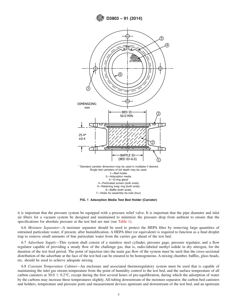
residual radioactivity. An acceptable bed construction is shown in Fig. 1 with critical dimensions noted.
6.2.2 Clamping assemblies are needed for sample and backup beds. The only requirements for these assemblies are that they
provide a smooth sealing face, uniform alignment of bed canisters, and sufficient clamping force so that the leak test in 10.2 can
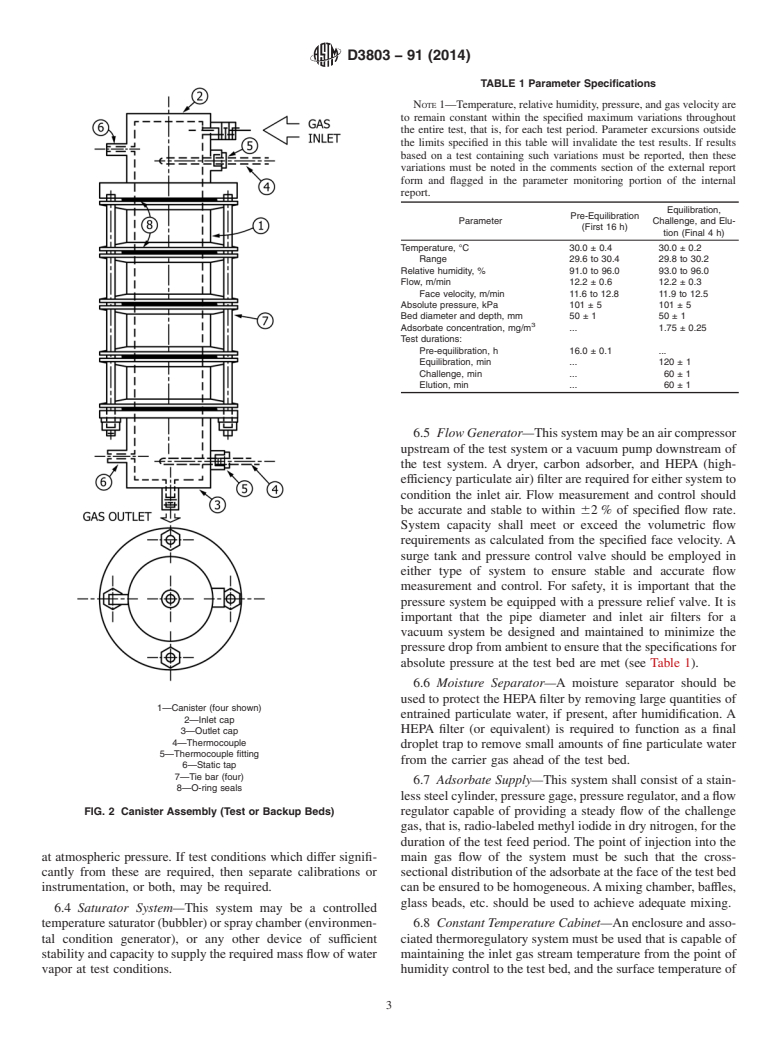
be met. A suggested design for clamping assemblies is shown in Fig. 2.
6.3 A schematic of a generalized test system is shown in Fig. 3. This system is designed to operate at approximately 30°C and
95 % relative humidity, with a gas flow of 24.7 L/min at atmospheric pressure. If test conditions which differ significantly from
these are required, then separate calibrations or instrumentation, or both, may be required.
6.4 Saturator System—This system may be a controlled temperature saturator (bubbler) or spray chamber (environmental
condition generator), or any other device of sufficient stability and capacity to supply the required mass flow of water vapor at test
conditions.
6.5 Flow Generator—This system may be an air compressor upstream of the test system or a vacuum pump downstream of the
test system. A dryer, carbon adsorber, and HEPA (high-efficiency particulate air) filter are required for either system to condition
the inlet air. Flow measurement and control should be accurate and stable to within 62 % of specified flow rate. System capacity
shall meet or exceed the volumetric flow requirements as calculated from the specified face velocity. A surge tank and pressure
control valve should be employed in either type of system to ensure stable and accurate flow measurement and control. For safety,
D3803 − 91 (2014)
* Standard canister dimension may be used in multiples if desired.
Single test canisters of full depth may be used.
1—Bed holder
2—Adsorption media
3—O-ring gland
4—Perforated screen (both ends)
5—Retaining snap ring (both ends)
6—Baffle (both ends)
7—Holes for assembly tie-rods (four)
FIG. 1 Adsorption Media Test Bed Holder (Canister)
it is important that the pressure system be equipped with a pressure relief valve. It is important that the pipe diameter and inlet
air filters for a vacuum system be designed and maintained to minimize the pressure drop from ambient to ensure that the
specifications for absolute pressure at the test bed are met (see Table 1).
6.6 Moisture Separator—A moisture separator should be used to protect the HEPA filter by removing large quantities of
entrained particulate water, if present, after humidification. A HEPA filter (or equivalent) is required to function as a final droplet
trap to remove small amounts of fine particulate water from the carrier gas ahead of the test bed.
6.7 Adsorbate Supply—This system shall consist of a stainless steel cylinder, pressure gage, pressure regulator, and a flow
regulator capable of providing a steady flow of the challenge gas, that is, radio-labeled methyl iodide in dry nitrogen, for the
duration of the test feed period. The point of injection into the main gas flow of the system must be such that the cross-sectional
distribution of the adsorbate at the face of the test bed can be ensured to be homogeneous. A mixing chamber, baffles, glass beads,
etc. should be used to achieve adequate mixing.
6.8 Constant Temperature Cabinet—An enclosure and associated thermoregulatory system must be used that is capable of
maintaining the inlet gas stream temperature from the point of humidity control to the test bed, and the surface temperature of all
carbon canisters at 30.0 6 0.2°C, except during the first several hours of pre-equilibration, during which the adsorption of water
by the carbons may increase these temperatures slightly. All tubing downstream of the moisture separator, the carbon bed canisters
and holders, temperature and pressure ports and measurement devices upstream and downstream of the test bed, and an upstream
D3803 − 91 (2014)
1—Canister (four shown)
2—Inlet cap
3—Outlet cap
4—Thermocouple
5—Thermocouple fitting
6—Static tap
7—Tie bar (four)
8—O-ring seals
FIG. 2 Canister Assembly (Test or Backup Beds)
port and tubing to the dew point sensor all must be included within the temperature controlled enclosure. In addition, it is highly
recommended that a bypass line be included around the sample bed assembly to avoid exposing the sample to start-up conditions
possibly outside those specified.
6.9 Flow Measurement and Control—Mass flow controllers, control valve and orifice meter, rotameter or any other device with
adequate stability and demonstrated measurement system accuracy of 62 % of specified flow rate at the test conditions. All flow
measuring devices must use correction factors for interpretation and application to actual test conditions. These factors must be
carefully predetermined and documented. No flow measuring device should be located directly downstream of the test bed such
that it is subject to variable temperature and humidity conditions during a test as a result of water absorption by the carbon.
D3803 − 91 (2014)
TABLE 1 Parameter Specifications
NOTE 1—Temperature, relative humidity, pressure, and gas velocity are
to remain constant within the specified maximum variations throughout
the entire test, that is, for each test period. Parameter excursions outside
the limits specified in this table will invalidate the test results. If results
based on a test containing such variations must be reported, then these
variations must be noted in the comments section of the external report
form and flagged in the parameter monitoring portion of the internal
report.
Equilibration,
Pre-Equilibration
Parameter Challenge, and Elu-
(First 16 h)
tion (Final 4 h)
Temperature, °C 30.0 ± 0.4 30.0 ± 0.2
Range 29.6 to 30.4 29.8 to 30.2
Relative humidity, % 91.0 to 96.0 93.0 to 96.0
Flow, m/min 12.2 ± 0.6 12.2 ± 0.3
Face velocity, m/min 11.6 to 12.8 11.9 to 12.5
Absolute pressure, kPa 101 ± 5 101 ± 5
Bed diameter and depth, mm 50 ± 1 50 ± 1
Adsorbate concentration, mg/m . 1.75 ± 0.25
Test durations:
Pre-equilibration, h 16.0 ± 0.1 .
Equilibration, min . 120 ± 1
Challenge, min . 60 ± 1
Elution, min . 60 ± 1
6.10 Interconnecting Tubing—Tubing must be non-reactive with methyl iodide, such as stainless steel, glass, etc., with a
minimum of ⁄8-in. outside diameter, and kept as short as
...
Questions, Comments and Discussion
Ask us and Technical Secretary will try to provide an answer. You can facilitate discussion about the standard in here.