


ASTM E2109-01(2014)
(Test Method)Standard Test Methods for Determining Area Percentage Porosity in Thermal Sprayed Coatings
Standard Test Methods for Determining Area Percentage Porosity in Thermal Sprayed Coatings
SIGNIFICANCE AND USE
4.1 TSCs are susceptible to the formation of porosity due to a lack of fusion between sprayed particles or the expansion of gases generated during the spraying process. The determination of area percent porosity is important in order to monitor the effect of variable spray parameters and the suitability of a coating for its intended purpose. Depending on application, some or none of this porosity may be tolerable.
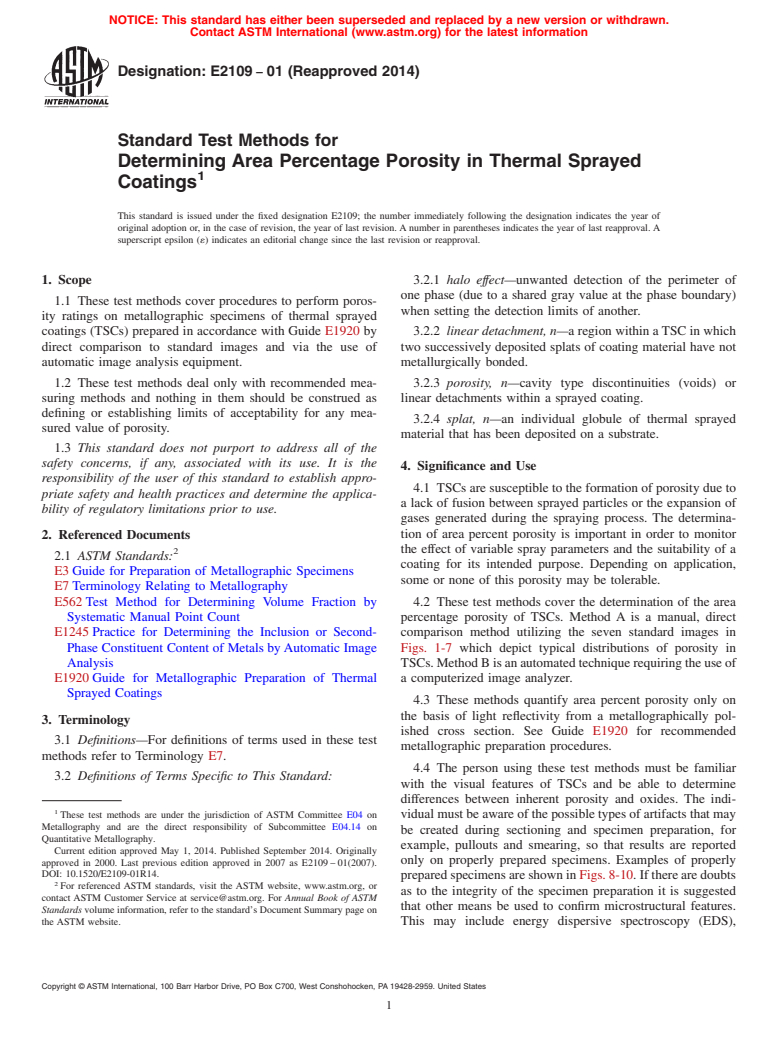
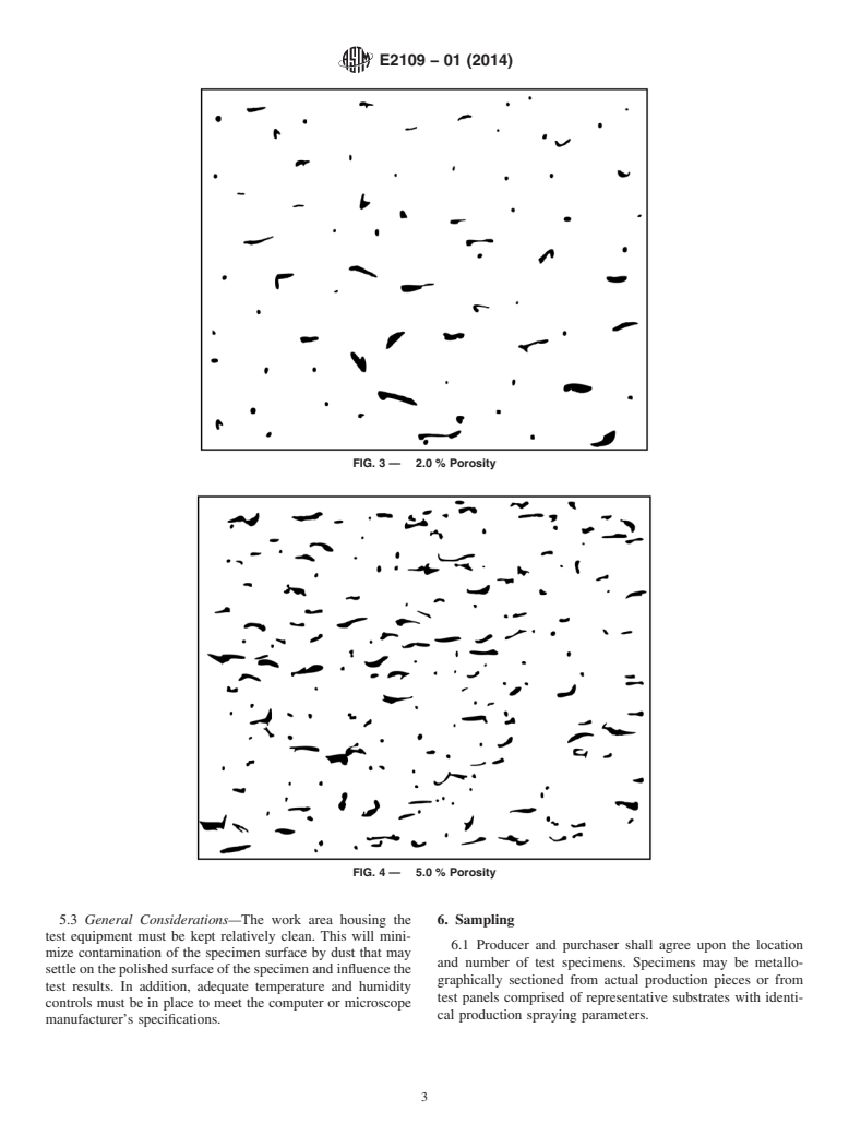
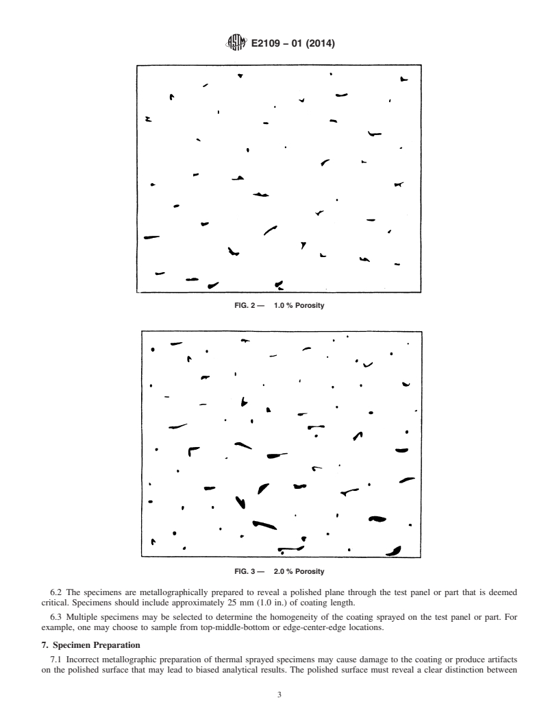
4.2 These test methods cover the determination of the area percentage porosity of TSCs. Method A is a manual, direct comparison method utilizing the seven standard images in Figs. 1-7 which depict typical distributions of porosity in TSCs. Method B is an automated technique requiring the use of a computerized image analyzer.
4.3 These methods quantify area percent porosity only on the basis of light reflectivity from a metallographically polished cross section. See Guide E1920 for recommended metallographic preparation procedures.
4.4 The person using these test methods must be familiar with the visual features of TSCs and be able to determine differences between inherent porosity and oxides. The individual must be aware of the possible types of artifacts that may be created during sectioning and specimen preparation, for example, pullouts and smearing, so that results are reported only on properly prepared specimens. Examples of properly prepared specimens are shown in Figs. 8-10. If there are doubts as to the integrity of the specimen preparation it is suggested that other means be used to confirm microstructural features. This may include energy dispersive spectroscopy (EDS), wavelength dispersive spectroscopy (WDS) or cryogenic fracture of the coating followed by analysis of the fractured surfaces with a scanning electron microscope (SEM).
SCOPE
1.1 These test methods cover procedures to perform porosity ratings on metallographic specimens of thermal sprayed coatings (TSCs) prepared in accordance with Guide E1920 by direct comparison to standard images and via the use of automatic image analysis equipment.
1.2 These test methods deal only with recommended measuring methods and nothing in them should be construed as defining or establishing limits of acceptability for any measured value of porosity.
1.3 This standard does not purport to address all of the safety concerns, if any, associated with its use. It is the responsibility of the user of this standard to establish appropriate safety and health practices and determine the applicability of regulatory limitations prior to use.
General Information
Buy Standard
Standards Content (Sample)
NOTICE: This standard has either been superseded and replaced by a new version or withdrawn.
Contact ASTM International (www.astm.org) for the latest information
Designation: E2109 − 01 (Reapproved 2014)
Standard Test Methods for
Determining Area Percentage Porosity in Thermal Sprayed
Coatings
This standard is issued under the fixed designation E2109; the number immediately following the designation indicates the year of
original adoption or, in the case of revision, the year of last revision. A number in parentheses indicates the year of last reapproval. A
superscript epsilon (´) indicates an editorial change since the last revision or reapproval.
1. Scope 3.2.1 halo effect—unwanted detection of the perimeter of
one phase (due to a shared gray value at the phase boundary)
1.1 These test methods cover procedures to perform poros-
when setting the detection limits of another.
ity ratings on metallographic specimens of thermal sprayed
coatings (TSCs) prepared in accordance with Guide E1920 by
3.2.2 linear detachment, n—a region within a TSC in which
direct comparison to standard images and via the use of two successively deposited splats of coating material have not
automatic image analysis equipment. metallurgically bonded.
1.2 These test methods deal only with recommended mea- 3.2.3 porosity, n—cavity type discontinuities (voids) or
suring methods and nothing in them should be construed as
linear detachments within a sprayed coating.
defining or establishing limits of acceptability for any mea-
3.2.4 splat, n—an individual globule of thermal sprayed
sured value of porosity.
material that has been deposited on a substrate.
1.3 This standard does not purport to address all of the
safety concerns, if any, associated with its use. It is the
4. Significance and Use
responsibility of the user of this standard to establish appro-
4.1 TSCs are susceptible to the formation of porosity due to
priate safety and health practices and determine the applica-
a lack of fusion between sprayed particles or the expansion of
bility of regulatory limitations prior to use.
gases generated during the spraying process. The determina-
tion of area percent porosity is important in order to monitor
2. Referenced Documents
the effect of variable spray parameters and the suitability of a
2.1 ASTM Standards:
coating for its intended purpose. Depending on application,
E3 Guide for Preparation of Metallographic Specimens
some or none of this porosity may be tolerable.
E7 Terminology Relating to Metallography
E562 Test Method for Determining Volume Fraction by 4.2 These test methods cover the determination of the area
Systematic Manual Point Count percentage porosity of TSCs. Method A is a manual, direct
E1245 Practice for Determining the Inclusion or Second- comparison method utilizing the seven standard images in
Phase Constituent Content of Metals byAutomatic Image Figs. 1-7 which depict typical distributions of porosity in
Analysis TSCs.MethodBisanautomatedtechniquerequiringtheuseof
E1920 Guide for Metallographic Preparation of Thermal a computerized image analyzer.
Sprayed Coatings
4.3 These methods quantify area percent porosity only on
the basis of light reflectivity from a metallographically pol-
3. Terminology
ished cross section. See Guide E1920 for recommended
3.1 Definitions—For definitions of terms used in these test
metallographic preparation procedures.
methods refer to Terminology E7.
4.4 The person using these test methods must be familiar
3.2 Definitions of Terms Specific to This Standard:
with the visual features of TSCs and be able to determine
differences between inherent porosity and oxides. The indi-
These test methods are under the jurisdiction of ASTM Committee E04 on
vidual must be aware of the possible types of artifacts that may
Metallography and are the direct responsibility of Subcommittee E04.14 on
be created during sectioning and specimen preparation, for
Quantitative Metallography.
example, pullouts and smearing, so that results are reported
Current edition approved May 1, 2014. Published September 2014. Originally
only on properly prepared specimens. Examples of properly
approved in 2000. Last previous edition approved in 2007 as E2109 – 01(2007).
DOI: 10.1520/E2109-01R14.
preparedspecimensareshowninFigs.8-10.Iftherearedoubts
For referenced ASTM standards, visit the ASTM website, www.astm.org, or
as to the integrity of the specimen preparation it is suggested
contact ASTM Customer Service at service@astm.org. For Annual Book of ASTM
that other means be used to confirm microstructural features.
Standards volume information, refer to the standard’s Document Summary page on
the ASTM website. This may include energy dispersive spectroscopy (EDS),
Copyright © ASTM International, 100 Barr Harbor Drive, PO Box C700, West Conshohocken, PA 19428-2959. United States
E2109 − 01 (2014)
FIG. 1 — 0.5 % Porosity
FIG. 2 — 1.0 % Porosity
wavelength dispersive spectroscopy (WDS) or cryogenic frac- groundglassviewingscreen,videomonitororimagerecording
ture of the coating followed by analysis of the fractured media, such as film or video prints.
surfaces with a scanning electron microscope (SEM).
5.2 Test Method B—Test Method B requires a reflected light
metallurgical microscope, upright or inverted, equipped with
5. Apparatus
suitable objectives and interfaced to a video/digital image
5.1 Test Method A—Test MethodArequires a reflected light capture and analysis system. The microscope may be equipped
metallurgical microscope, upright or inverted, equipped with with an automatic or manual stage. The use of an automated
suitable objectives and capable of projecting an image onto a stage should reduce operator fatigue.
E2109 − 01 (2014)
FIG. 3 — 2.0 % Porosity
FIG. 4 — 5.0 % Porosity
5.3 General Considerations—The work area housing the 6. Sampling
test equipment must be kept relatively clean. This will mini-
6.1 Producer and purchaser shall agree upon the location
mize contamination of the specimen surface by dust that may
and number of test specimens. Specimens may be metallo-
settle on the polished surface of the specimen and influence the
graphically sectioned from actual production pieces or from
test results. In addition, adequate temperature and humidity
test panels comprised of representative substrates with identi-
controls must be in place to meet the computer or microscope
cal production spraying parameters.
manufacturer’s specifications.
E2109 − 01 (2014)
FIG. 5 — 8.0 % Porosity
FIG. 6 — 10.0 % Porosity
6.2 Thespecimensaremetallographicallypreparedtoreveal For example, one may choose to sample from top-middle-
a polished plane through the test panel or part that is deemed bottom or edge-center-edge locations.
critical. Specimens should include approximately 25 mm (1.0
in.) of coating length. 7. Specimen Preparation
6.3 Multiple specimens may be selected to determine the 7.1 Incorrect metallographic preparation of thermal sprayed
homogeneity of the coating sprayed on the test panel or part. specimens may cause damage to the coating or produce
E2109 − 01 (2014)
FIG. 7 — 15.0 % Porosity
NOTE 1—V = void, O = oxide, L = linear detachment
FIG. 8 Ni/Al TSC—500X
artifacts on the polished surface that may lead to biased 7.4 Damage to a brittle, porous TSC during specimen
analytical results. The polished surface must reveal a clear preparation is minimized when the specimen is vacuum im-
distinction between inherent porosity, foreign matter, scratches pregnated with a low viscosity epoxy. The epoxy mounting
and oxides. Polishing must not alter the true appearance of the compoundfillsthesurfaceconnectedporosityandaddssupport
inherent porosity by excessive relief, pitting pullout, or smear- to the coating during preparation.
ing.
7.5 Use of a dyed epoxy or fluorescent additive may be
3,4
7.2 Generalmetallographicspecimenpreparationguidelines helpful in microstructural interpretation . Depending on the
and recommendations are given in Practice E3; however, additive, a treated epoxy will fluoresce or appear as a distinct
manual metallographic preparation methods are not recom-
mended for TSCs.
Street, K.W. and Leonhardt, T.A., “Fluorescence Microscopy for the Charac-
7.3 Use of automatic grinding and polishing equipment is
terization of Structural Integrity,” NASA Technical Memorandum 105253, 1991.
recommended. Specific information regarding the preparation
Geary, A.R., “Metallographic Evaluation of Thermal Spray Coatings,” Micro-
of TSCs using automated techniques is addressed in Guide
structural Science,Vol19,D.A.Wheeler,et.al.,eds.,IMSandASMIntl.,Materials
E1920. Park, OH, 1992, pp. 637–650.
E2109 − 01 (2014)
NOTE 1—V = void, G = embedded grit, L = linear detachment
FIG. 9 Monel TSC—200X
NOTE 1—V = void, O = oxide, G = embedded grit
FIG. 10 Alloy 625 TSC—200X
color when viewed with the appropriate light microscopy 8.1.2 Place the properly prepared specimen on the micro-
technique. This can eliminate any ambiguities concerning scope stage and divert the image to a ground glass viewing
oxide content or pull-outs. Excitation and emission filters, screen or video monitor. Alternately, it may be recorded as a
darkfield illumination or polarized light may be required to hard copy print.
reveal the color created by the dye or pigment. Consult the 8.1.3 Select a magnification that allows resolution of the
manufacturer’s directions for the proper use of these materials.
voids and best fills the screen with the entire coating thickness.
Often, a compromise must be reached whereby the entire
8. Test Procedure
coatingthicknessisnotvisiblebutareductioninmagnification
8.1 Test Method A (Direct Comparison): would jeopardize the resolution of voids. It is more important
8.1.1 This test method utilizes the images in Figs. 1-7 for to resolve all voids that contribute significantly to the total
comparison to microscopic fields of view on a polished porosity area percentage. During this analysis the operator
specimen. Each figure has been assigned a value representing must be able to distinguish the difference between oxides and
varying degrees of porosity. epoxy infiltrated into voids.
E2109 − 01 (2014)
8.1.4 Compare the image on
...
This document is not an ASTM standard and is intended only to provide the user of an ASTM standard an indication of what changes have been made to the previous version. Because
it may not be technically possible to adequately depict all changes accurately, ASTM recommends that users consult prior editions as appropriate. In all cases only the current version
of the standard as published by ASTM is to be considered the official document.
Designation: E2109 − 01 (Reapproved 2007) E2109 − 01 (Reapproved 2014)
Standard Test Methods for
Determining Area Percentage Porosity in Thermal Sprayed
Coatings
This standard is issued under the fixed designation E2109; the number immediately following the designation indicates the year of
original adoption or, in the case of revision, the year of last revision. A number in parentheses indicates the year of last reapproval. A
superscript epsilon (´) indicates an editorial change since the last revision or reapproval.
1. Scope
1.1 These test methods cover procedures to perform porosity ratings on metallographic specimens of thermal sprayed coatings
(TSCs) prepared in accordance with Guide E1920 by direct comparison to standard images and via the use of automatic image
analysis equipment.
1.2 These test methods deal only with recommended measuring methods and nothing in them should be construed as defining
or establishing limits of acceptability for any measured value of porosity.
1.3 This standard does not purport to address all of the safety concerns, if any, associated with its use. It is the responsibility
of the user of this standard to establish appropriate safety and health practices and determine the applicability of regulatory
limitations prior to use.
2. Referenced Documents
2.1 ASTM Standards:
E3 Guide for Preparation of Metallographic Specimens
E7 Terminology Relating to Metallography
E562 Test Method for Determining Volume Fraction by Systematic Manual Point Count
E1245 Practice for Determining the Inclusion or Second-Phase Constituent Content of Metals by Automatic Image Analysis
E1920 Guide for Metallographic Preparation of Thermal Sprayed Coatings
3. Terminology
3.1 Definitions—For definitions of terms used in these test methods refer to Terminology E7.
3.2 Definitions of Terms Specific to This Standard:
3.2.1 halo effect—unwanted detection of the perimeter of one phase (due to a shared gray value at the phase boundary) when
setting the detection limits of another.
3.2.2 linear detachment, n—a region within a TSC in which two successively deposited splats of coating material have not
metallurgically bonded.
3.2.3 porosity, n—cavity type discontinuities (voids) or linear detachments within a sprayed coating.
3.2.4 splat, n—an individual globule of thermal sprayed material that has been deposited on a substrate.
4. Significance and Use
4.1 TSCs are susceptible to the formation of porosity due to a lack of fusion between sprayed particles or the expansion of gases
generated during the spraying process. The determination of area percent porosity is important in order to monitor the effect of
variable spray parameters and the suitability of a coating for its intended purpose. Depending on application, some or none of this
porosity may be tolerable.
ThisThese test method ismethods are under the jurisdiction of ASTM Committee E04 on Metallography and isare the direct responsibility of Subcommittee E04.14 on
Quantitative Metallography.
Current edition approved May 1, 2007May 1, 2014. Published May 2007September 2014. Originally approved in 2000. Last previous edition approved in 20012007 as
E2109 – 01.E2109 – 01(2007). DOI: 10.1520/E2109-01R07.10.1520/E2109-01R14.
For referenced ASTM standards, visit the ASTM website, www.astm.org, or contact ASTM Customer Service at service@astm.org. For Annual Book of ASTM Standards
volume information, refer to the standard’s Document Summary page on the ASTM website.
Copyright © ASTM International, 100 Barr Harbor Drive, PO Box C700, West Conshohocken, PA 19428-2959. United States
E2109 − 01 (2014)
4.2 These test methods cover the determination of the area percentage porosity of TSCs. Method A is a manual, direct
comparison method utilizing the seven standard images in Figs. 1-7 which depict typical distributions of porosity in TSCs. Method
B is an automated technique requiring the use of a computerized image analyzer.
4.3 These methods quantify area percent porosity only on the basis of light reflectivity from a metallographically polished cross
section. See Guide E1920 for recommended metallographic preparation procedures.
4.4 The person using these test methods must be familiar with the visual features of TSCs and be able to determine differences
between inherent porosity and oxides. The individual must be aware of the possible types of artifacts that may be created during
sectioning and specimen preparation, for example, pullouts and smearing, so that results are reported only on properly prepared
specimens. Examples of properly prepared specimens are shown in Figs. 8-10. If there are doubts as to the integrity of the specimen
preparation it is suggested that other means be used to confirm microstructural features. This may include energy dispersive
spectroscopy (EDS), wavelength dispersive spectroscopy (WDS) or cryogenic fracture of the coating followed by analysis of the
fractured surfaces with a scanning electron microscope (SEM).
5. Apparatus
5.1 Test Method A—Test Method A requires a reflected light metallurgical microscope, upright or inverted, equipped with
suitable objectives and capable of projecting an image onto a ground glass viewing screen, video monitor or image recording
media, such as film or video prints.
5.2 Test Method B—Test Method B requires a reflected light metallurgical microscope, upright or inverted, equipped with
suitable objectives and interfaced to a video/digital image capture and analysis system. The microscope may be equipped with an
automatic or manual stage. The use of an automated stage should reduce operator fatigue.
5.3 General Considerations—The work area housing the test equipment must be kept relatively clean. This will minimize
contamination of the specimen surface by dust that may settle on the polished surface of the specimen and influence the test results.
In addition, adequate temperature and humidity controls must be in place to meet the computer or microscope manufacturer’s
specifications.
6. Sampling
6.1 Producer and purchaser shall agree upon the location and number of test specimens. Specimens may be metallographically
sectioned from actual production pieces or from test panels comprised of representative substrates with identical production
spraying parameters.
FIG. 1 — 0.5 % Porosity
E2109 − 01 (2014)
FIG. 2 — 1.0 % Porosity
FIG. 3 — 2.0 % Porosity
6.2 The specimens are metallographically prepared to reveal a polished plane through the test panel or part that is deemed
critical. Specimens should include approximately 25 mm (1.0 in.) of coating length.
6.3 Multiple specimens may be selected to determine the homogeneity of the coating sprayed on the test panel or part. For
example, one may choose to sample from top-middle-bottom or edge-center-edge locations.
7. Specimen Preparation
7.1 Incorrect metallographic preparation of thermal sprayed specimens may cause damage to the coating or produce artifacts
on the polished surface that may lead to biased analytical results. The polished surface must reveal a clear distinction between
E2109 − 01 (2014)
FIG. 4 — 5.0 % Porosity
FIG. 5 — 8.0 % Porosity
inherent porosity, foreign matter, scratches and oxides. Polishing must not alter the true appearance of the inherent porosity by
excessive relief, pitting pullout, or smearing.
7.2 General metallographic specimen preparation guidelines and recommendations are given in Practice E3; however, manual
metallographic preparation methods are not recommended for TSCs.
7.3 Use of automatic grinding and polishing equipment is recommended. Specific information regarding the preparation of
TSCs using automated techniques is addressed in Guide E1920.
E2109 − 01 (2014)
FIG. 6 — 10.0 % Porosity
FIG. 7 — 15.0 % Porosity
7.4 Damage to a brittle, porous TSC during specimen preparation is minimized when the specimen is vacuum impregnated with
a low viscosity epoxy. The epoxy mounting compound fills the surface connected porosity and adds support to the coating during
preparation.
3,4
7.5 Use of a dyed epoxy or fluorescent additive may be helpful in microstructural interpretation . Depending on the additive,
a treated epoxy will fluoresce or appear as a distinct color when viewed with the appropriate light microscopy technique. This can
Street, K.W. and Leonhardt, T.A., “Fluorescence Microscopy for the Characterization of Structural Integrity,” NASA Technical Memorandum 105253, 1991.
E2109 − 01 (2014)
NOTE 1—V = void, O = oxide, L = linear detachment
FIG. 8 Ni/Al TSC—500X
NOTE 1—V = void, G = embedded grit, L = linear detachment
FIG. 9 Monel TSC—200X
eliminate any ambiguities concerning oxide content or pull-outs. Excitation and emission filters, darkfield illumination or polarized
light may be required to reveal the color created by the dye or pigment. Consult the manufacturer’s directions for the proper use
of these materials.
8. Test Procedure
8.1 Test Method A (Direct Comparison):
8.1.1 This test method utilizes the images in Figs. 1-7 for comparison to microscopic fields of view on a polished specimen.
Each figure has been assigned a value representing varying degrees of porosity.
8.1.2 Place the properly prepared specimen on the microscope stage and divert the image to a ground glass viewing screen or
video monitor. Alternately, it may be recorded as a hard copy print.
8.1.3 Select a magnification that allows resolution of the voids and best fills the screen with the entire coating thickness. Often,
a compromise must be reached whereby the entire coating thickness is not visible but a reduction in magnification would
jeopardize the resolution of voids. It is more important to resolve all voids that contribute significantly to the total porosity area
percentage. During this analysis the operator must be able to distinguish the difference between oxides and epoxy infiltrated into
voids.
Geary, A.R., “Metallographic Evaluation of Thermal Spray Coatings,” Microstructural Science, Vol 19, D. A. Wheeler, et. al., eds., IMS and ASM Intl., Materials Park,
OH, 1992, pp. 637–650.
...
Questions, Comments and Discussion
Ask us and Technical Secretary will try to provide an answer. You can facilitate discussion about the standard in here.