


ASTM G109-07(2013)
(Test Method)Standard Test Method for Determining Effects of Chemical Admixtures on Corrosion of Embedded Steel Reinforcement in Concrete Exposed to Chloride Environments
Standard Test Method for Determining Effects of Chemical Admixtures on Corrosion of Embedded Steel Reinforcement in Concrete Exposed to Chloride Environments
SIGNIFICANCE AND USE
3.1 This test method provides a reliable means for predicting the inhibiting or corrosive properties of admixtures to be used in concrete.
3.2 This test method is useful for development studies of corrosion inhibitors to be used in concrete.
3.3 This test method has been used elsewhere with good agreement between corrosion as measured by this test method and corrosion damage on the embedded steel (1-4).5 This test method might not properly rank the performance of different corrosion inhibitors, especially at concrete covers over the steel less than 40 mm (1.5 in.) or water-to-cement ratios above 0.45. The concrete mixture proportions and cover over the steel are chosen to accelerate chloride ingress. Some inhibitors might have an effect on this process, which could lead to results that would differ from what would be expected in actual use (5).
SCOPE
1.1 This test method covers a procedure for determining the effects of chemical admixtures on the corrosion of metals in concrete. This test method can be used to evaluate materials intended to inhibit chloride-induced corrosion of steel in concrete. It can also be used to evaluate the corrosivity of admixtures in a chloride environment.
1.2 The values stated in SI units are to be regarded as standard. The values given in parentheses are for information only.
1.3 This standard does not purport to address all of the safety concerns, if any, associated with its use. It is the responsibility of the user of this standard to establish appropriate safety and health practices and determine the applicability of regulatory limitations prior to use.
General Information

Standards Content (Sample)
NOTICE: This standard has either been superseded and replaced by a new version or withdrawn.
Contact ASTM International (www.astm.org) for the latest information
Designation: G109 − 07 (Reapproved 2013)
Standard Test Method for
Determining Effects of Chemical Admixtures on Corrosion
of Embedded Steel Reinforcement in Concrete Exposed to
Chloride Environments
This standard is issued under the fixed designation G109; the number immediately following the designation indicates the year of
original adoption or, in the case of revision, the year of last revision.Anumber in parentheses indicates the year of last reapproval.A
superscript epsilon (´) indicates an editorial change since the last revision or reapproval.
1. Scope C511Specification for Mixing Rooms, Moist Cabinets,
Moist Rooms, and Water Storage Tanks Used in the
1.1 Thistestmethodcoversaprocedurefordeterminingthe
Testing of Hydraulic Cements and Concretes
effects of chemical admixtures on the corrosion of metals in
C876Test Method for Corrosion Potentials of Uncoated
concrete. This test method can be used to evaluate materials
Reinforcing Steel in Concrete
intended to inhibit chloride-induced corrosion of steel in
C881/C881MSpecification for Epoxy-Resin-Base Bonding
concrete. It can also be used to evaluate the corrosivity of
Systems for Concrete
admixtures in a chloride environment.
C1152/C1152MTest Method for Acid-Soluble Chloride in
1.2 The values stated in SI units are to be regarded as
Mortar and Concrete
standard. The values given in parentheses are for information
D448Classification for Sizes of Aggregate for Road and
only.
Bridge Construction
1.3 This standard does not purport to address all of the D632Specification for Sodium Chloride
safety concerns, if any, associated with its use. It is the
E177Practice for Use of the Terms Precision and Bias in
responsibility of the user of this standard to establish appro- ASTM Test Methods
priate safety and health practices and determine the applica-
E691Practice for Conducting an Interlaboratory Study to
bility of regulatory limitations prior to use. Determine the Precision of a Test Method
G3Practice for Conventions Applicable to Electrochemical
2. Referenced Documents
Measurements in Corrosion Testing
G15TerminologyRelatingtoCorrosionandCorrosionTest-
2.1 ASTM Standards:
ing (Withdrawn 2010)
A615/A615MSpecificationforDeformedandPlainCarbon-
G33Practice for Recording Data from Atmospheric Corro-
Steel Bars for Concrete Reinforcement
sion Tests of Metallic-Coated Steel Specimens
C33Specification for Concrete Aggregates
G46Guide for Examination and Evaluation of Pitting Cor-
C143/C143MTest Method for Slump of Hydraulic-Cement
rosion
Concrete
2.2 NACE Standards:
C150Specification for Portland Cement
SSPC-SP 5/NACE No. 1White Metal Blast Cleaning
C173/C173MTestMethodforAirContentofFreshlyMixed
Concrete by the Volumetric Method
3. Significance and Use
C192/C192MPracticeforMakingandCuringConcreteTest
Specimens in the Laboratory
3.1 This test method provides a reliable means for predict-
C231Test Method for Air Content of Freshly Mixed Con-
ing the inhibiting or corrosive properties of admixtures to be
crete by the Pressure Method
used in concrete.
3.2 This test method is useful for development studies of
corrosion inhibitors to be used in concrete.
This test method is under the jurisdiction of ASTM Committee G01 on
3.3 This test method has been used elsewhere with good
Corrosion of Metals and is the direct responsibility of Subcommittee G01.14 on
Corrosion of Metals in Construction Materials.
agreement between corrosion as measured by this test method
CurrenteditionapprovedMay1,2013.PublishedJuly2013.Originallyapproved
in1992.Lastpreviouseditionapprovedin2007asG109–07.DOI:10.1520/G0109-
07R13.
2 3
For referenced ASTM standards, visit the ASTM website, www.astm.org, or The last approved version of this historical standard is referenced on
contact ASTM Customer Service at service@astm.org. For Annual Book of ASTM www.astm.org.
Standards volume information, refer to the standard’s Document Summary page on Available from The Society for Protective Coatings (SSPC), 40 24th St., 6th
the ASTM website. Floor, Pittsburgh, PA 15222-4656.
Copyright © ASTM International, 100 Barr Harbor Drive, PO Box C700, West Conshohocken, PA 19428-2959. United States
G109 − 07 (2013)
and corrosion damage on the embedded steel (1-4). This test 5.11 EpoxySealer,forapplicationtotheconcretespecimens
method might not properly rank the performance of different after manufacture. This sealer shall be of Type III, Grade 1,
7,9
corrosioninhibitors,especiallyatconcretecoversoverthesteel Class C in accordance with Specification C881/C881M.
lessthan40mm(1.5in.)orwater-to-cementratiosabove0.45.
5.12 Plastic Dams, 75-mm (3-in.) wide and 150-mm (6-in.)
The concrete mixture proportions and cover over the steel are
longwithaminimumheightof75mm(3in.)forplacementon
chosen to accelerate chloride ingress. Some inhibitors might
the test specimens. The wall thickness shall be 61mm( ⁄8 6
have an effect on this process, which could lead to results that
⁄32 in.
would differ from what would be expected in actual use (5).
5.13 Silicone Caulk, for sealing the outside of the plastic
7,10
4. Apparatus dam to the top of the concrete specimen.
4.1 The apparatus required for the evaluation of corrosion
5.14 Reference Electrode, such as a saturated calomel or
inhibitors includes a high impedance voltmeter (at least one silver/silver chloride electrode for measuring the corrosion
Mohm) capable of measuring to 0.01 mV, a 100 Ω (65%)
potential of the bars, as defined in Terminology G15.
resistor.
5.15 Hexane.
5. Reagents and Materials
6. Preparation of Test Specimens
5.1 Cement, that conforms to Type I or Type II of Specifi-
6.1 Power wire brush or sand blast the bars to near white
cation C150. Coarse aggregate shall conform to Specification
metal (see SSPC-SP 5/NACE No. 1), clean by soaking in
C33 and Classification D448, with nominal maximum size
hexane, and allow to air dry.
3 3
between 9.5 and 19 mm ( ⁄8 and ⁄4 in.).
NOTE3—Picklingthebarswith10%sulfuricacidfor10to15minand
NOTE 1—Preferred maximum size aggregate is 12.5 mm (0.5 in.).
rinsing with potable water prior to wire brushing is recommended when
5.2 Steel Reinforcement Bars, deformed, meeting the re- the bars have an excessive amount of rust.
quirement of Specification A615/A615M; with a diameter
6.2 Use the same method to clean all bars in the test
between 10 mm (0.4 in.) and 16 mm (0.6 in.), and a length of
program.
360mm(14in.),drilledandtappedatoneendtobefittedwith
6.3 Drillandtaponeendofeachbar,attachastainlesssteel
coarse-thread stainless steel and nuts, as described in 5.3 and
screw and two nuts, as described in 5.3 and 5.4, and tape each
5.4.Thesebarsshallbeusedtomanufacturethetestspecimens,
endofthebarwithelectroplater’stapesothata200-mm(8-in.)
as described in Section 6.
portioninthemiddleofthebarisbare.Placea90-mm(3.5in.)
NOTE 2—Interlaboratory test program and statistical data in Section 11
length of neoprene tubing, as described in 5.8, over the
are based upon 13-mm (0.5-in.) steel bars, 12.5-mm maximum size
electroplater’s tape at each end of the bar, and fill the length of
aggregate, and 19-mm (0.75-in.) and 25-mm (1 in.) cover.
tubingprotrudingfromthebarendswiththetwo-partepoxy,as
5.3 316 Stainless Steel Screws, with diameter smaller than
described in 5.5.
bar diameter (coarse thread<5mm (0.2 in.)), 25 to 35-mm (1
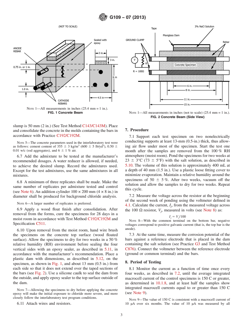
6.4 Specimensizeis280×150×115mm(11×6×4.5in.).
to 1.5-in.) long (one per bar).
Place two bars, as described in 5.2, 25 mm (1 in.) from the
5.4 316 Stainless Steel Nuts,twoperbartofitstainlesssteel
bottom, and one bar at the top such that the distance from its
screws, as described in 5.3.
top to the top surface of the specimen is twice the maximum
6,7
aggregate size, as shown in Fig. 1.
5.5 Two-part Waterproof Epoxy —This epoxy shall meet
the chemical resistance requirements of a Type IV, Grade 3,
NOTE 4—For example, for a 12.5-mm (0.5 in.) aggregate, place the top
Class E of Specification C881/C881M.
bar 25 mm (1 in.) from the surface. For a 9.5-mm (0.375-in.) aggregate,
place the bar 19 mm (0.75 in.) from the top surface.
5.6 Sulfuric Acid, 10% by mass, for pickling (optional).
7,8 6.5 Place the bars in the molds so that 40 mm (approxi-
5.7 Electroplater’s Tape.
mately 1.5 in.) of the bars are protected within each exit end
5.8 NeopreneTubing,with3-mm( ⁄8-in.)wallthicknessand
from the concrete (minimizes edge effects). This will expose
the same ID as the diameter of the bar used.
200mm(8in.)ofsteel.Placethebarswiththelongitudinalribs
so that they are nearer the side of the beam, that is, both ridges
5.9 Sodium Chloride, complying with Specification D632.
are equidistant from the top or bottom of the specimen.
5.10 Salt Solution,preparedbydissolving3partsofsodium
6.6 Make the concrete specimens (controls and those with
chloride (as described in 5.9) in 97 parts of water mass.
admixtures to be tested) in accordance with Practice C192/
C192M, using the same source of materials. Determine the air
The boldface numbers in parentheses refer to a list of references at the end of
content, using either Test Method C231 or C173/C173M. The
this standard.
The sole source of supply of the apparatus known to the committee at this time
water-to-cementratio(w/c)shallnotexceed0.5.Theminimum
is PC-Epoxy, made by Protective Coating Co., Allentown, PA.
If you are aware of alternative suppliers, please provide this information to
ASTM International Headquarters. Your comments will receive careful consider-
1 9
ation at a meeting of the responsible technical committee, which you may attend. The sole source of supply of the apparatus known to the committee at this time
The sole source of supply of the apparatus known to the committee at this time is Epoxy Concrete Scaler # 12560, made by Devcon.
isMinnesotaMiningandManufacturingCompany(3M),1999Mt.ReadBoulevard, Thesolesourceofsupplyoftheapparatusknowntothecommitteeatthistime
Rochester, NY 14615. is 3M Marine Adhesive 5200.
G109 − 07 (2013)
NOTE 1—All measurements in inches (25.4 mm=1 in.).
FIG. 1 Concrete Beam NOTE 1—All measurements in inches (not to scale) (25.4 mm=1 in.).
FIG. 2 Concrete Beam (Side View)
slumpis50mm(2in.)(SeeTestMethodC143/C143M).Place
7. Procedure
andconsolidatetheconcreteinthemoldscontainingthebarsin
accordance with Practice C192/C192M.
7.1 Support each test specimen on two nonelectrically
conducting supports at least 13-mm (0.5-in.) thick, thus allow-
NOTE 5—The concrete parameters used in the interlaboratory test were
3 3
as follows: cement content of 355 6 3 kg/m (600 6 5 lb/yd ), 0.50 6 ing air flow under most of the specimen. Start the test one
0.01 w/c (ssd aggregates), and 6 6 1% air.
month after the samples are removed from the 100% RH
atmosphere(moistroom).Pondthespecimensfortwoweeksat
6.7 Add the admixture to be tested at the manufacturer’s
23 6 3°C (73 6 5°F) with the salt solution, as described in
recommended dosages.Awater reducer is allowed, if needed,
5.10. The volume of this solution is approximately 400 mL at
to achieve the desired slump. Record the admixtures used.
a depth of 40 mm (1.5 in.). Use a plastic loose fitting cover to
Except for the test admixtures, use the same admixtures in all
minimizeevaporation.Maintainarelativehumidityaroundthe
mixtures.
specimens of 50 6 5%. After two weeks, vacuum off the
6.8 Aminimum of three replicates shall be made. Make the
solution and allow the samples to dry for two weeks. Repeat
same number of replicates per admixture tested and control
this cycle.
(see Note 6).An addition cylinder 100 × 200 mm (4 × 8in.) in
7.2 Measure the voltage across the resistor at the beginning
diameter shall be produced for background chloride analysis.
of the second week of ponding using the voltmeter defined in
NOTE 6—A larger number of replicates is preferred.
4.1. Calculate the current, I, from the measured voltage across
j
6.9 Apply a wood float finish after consolidation. After
the 100Ω resistor, V, measured in volts (see Note 8) as:
j
removal from the forms, cure the specimens for 28 days in a
I 5 V /100
j j
moist room in accordance withTest Method C192/C192M and
NOTE 8—With the common terminal on the bottom bar, negative
Specification C511.
voltages correspond to positive galvanic current (that is, the top bar is the
anode).
6.10 Upon removal from the moist room, hand wire brush
the specimens on the concrete top surface (wood floated 7.3 Atthesametime,measurethecorrosionpotentialofthe
bars against a reference electrode that is placed in the dam
surface).Allow the specimens to dry for two weeks in a 50%
relative humidity (RH) environment before sealing the four containing the salt solution (see Practice G3 and Test Method
C876). Connect the voltmeter between the reference electrode
vertical sides with an epoxy sealer, as described in 5.11,in
accordance with the manufacturer’s recommendation. Place a (ground or common terminal) and the bars.
plastic dam with dimensions, as described in 5.12,onthe
8. Period of Testing
specimen, as shown in Fig. 1, and about 13 mm (0.5 in.) from
each side so that it does not extend over the taped sections of
8.1 Monitor the current as a function of time once every
the bars (see Fig. 2). Use a silicone caulk to seal the dam from
four weeks, as described in 7.2, until the average integrated
theoutside,andapplyepoxysealertothetopsurfaceoutsideof
macrocell current of the control specimens is 150 C or greater,
the dam.
as determined in 10.1.8, and at least half the samples show
integrated macrocell currents equal to or greater than 150 C
NOTE 7—Allowing the specimens to dry before applying the concrete
(see Note 9).
epoxy will make the initial exposure to chloride more severe, and more
closely follow the interlaboratory test program conditions.
NOTE 9—The value of 150 C is consistent with a macrocell current of
6.11 Attach wires and resistors. 10 µA over six months. The value of 10 µA was measured by all
G109 − 07 (2013)
laboratories on all specimens showing corrosion (controls and samples
with calcium chloride at 19-mm ( ⁄4-in.) cover). This degree of integrated
macrocell current is sufficient to ensure the presence of sufficient
corrosion for visual evaluation.
8.2 In those cases where the admixtures being tested are
corrosive, end the test three full cycles after an average
integrated macrocell current of 75 C is observed and the
integrated macrocell current of at least half the specimens
being tested is equal or greater than 75 C.
9. Examination of Embedded Bars
9.1 At the conclusion of testing, break the specimens and
examine the reinforcement bars for extent of corrosion, mea-
sure the corroded area, and record the percentage of corroded
area recorded, as described in Practice G33.
NOT
...
Questions, Comments and Discussion
Ask us and Technical Secretary will try to provide an answer. You can facilitate discussion about the standard in here.