


ASTM F1826-00(2016)
(Specification)Standard Specification for Live Line and Measuring Telescoping Tools
Standard Specification for Live Line and Measuring Telescoping Tools
ABSTRACT
This specification covers mechanical and electrical testing and acceptance criteria for live line and measuring telescoping tools. It shall be used for design, routine, and acceptance testing. It does not cover multiple section or extendable section clampsticks. Mechanical test methods shall include horizontal bending deflection test, free fall impact test, tension test, and vertical deflection test. Measuring device tool need not to comply with mechanical strength requirements of this specification. Electrical test methods shall include electrical design test and electrical withstand test.
SCOPE
1.1 This specification covers mechanical and electrical testing and acceptance criteria for telescoping live line tools.
1.1.1 A tool designed only for use as a measuring device need not comply with mechanical strength requirements of this specification.
1.2 The use and maintenance of this equipment is beyond the scope of this specification.
1.3 This specification does not cover multiple section or extendable section clampsticks.
1.4 The values stated in inch-pound units are to be regarded as standard. The values given in parentheses are mathematical conversions to SI units that are provided for information only and are not considered standard.
1.5 The following safety hazards caveat pertains to Section 9 only. This standard does not purport to address all of the safety concerns, if any, associated with its use. It is the responsibility of the user of this standard to establish appropriate safety and health practices and determine the applicability of regulatory limitations prior to use.
General Information
Buy Standard


Standards Content (Sample)
NOTICE: This standard has either been superseded and replaced by a new version or withdrawn.
Contact ASTM International (www.astm.org) for the latest information
Designation:F1826 −00 (Reapproved 2016)
Standard Specification for
Live Line and Measuring Telescoping Tools
This standard is issued under the fixed designation F1826; the number immediately following the designation indicates the year of
original adoption or, in the case of revision, the year of last revision. A number in parentheses indicates the year of last reapproval. A
superscript epsilon (´) indicates an editorial change since the last revision or reapproval.
1. Scope 3.2 Definitions of Terms Specific to This Standard:
3.2.1 acceptance test, n—one made at the option of the
1.1 This specification covers mechanical and electrical test-
purchaser to verify that a product meets design criteria.
ing and acceptance criteria for telescoping live line tools.
1.1.1 A tool designed only for use as a measuring device 3.2.2 design test, n—one made on a sample treated as
representative of an industrial product. These tests generally
need not comply with mechanical strength requirements of this
specification. will not be repeated in quantity production.
3.2.3 dimensional check, n—measurements made to verify
1.2 The use and maintenance of this equipment is beyond
that a product complies with the dimension stated by the
the scope of this specification.
manufacturer.
1.3 This specification does not cover multiple section or
3.2.4 hydrophobic, adj—lacking affinity for water.
extendable section clampsticks.
3.2.5 routine test, n—a type of test made regularly on
1.4 The values stated in inch-pound units are to be regarded
production material.
as standard. The values given in parentheses are mathematical
conversions to SI units that are provided for information only 3.2.6 telescoping live line tool, n—an extendable multiple
and are not considered standard. section FRP tool designed to carry an attachment to perform
mechanical tasks.
1.5 The following safety hazards caveat pertains to Section
9 only. This standard does not purport to address all of the
3.2.7 telescoping measuring tool, n—anextendablemultiple
safety concerns, if any, associated with its use. It is the section FRP tool designed only to measure vertical heights.
responsibility of the user of this standard to establish appro-
3.2.8 visual inspection, n—a visual check made to detect
priate safety and health practices and determine the applica-
manufacturing defects.
bility of regulatory limitations prior to use.
4. Significance and Use
2. Referenced Documents
4.1 This specification shall be used for design, routine, and
2.1 ASTM Standards:
acceptance testing of live line and measuring telescoping tools.
D149 Test Method for Dielectric Breakdown Voltage and
DielectricStrengthofSolidElectricalInsulatingMaterials
5. Ordering Information
at Commercial Power Frequencies
5.1 Include the following information when ordering tele-
F819 Terminology Relating to Electrical Protective Equip-
scoping live line or measuring tools, or both:
ment for Workers
5.1.1 Quantity.
3. Terminology 5.1.2 Catalog number.
3.1 Definitions— Terminology used in this specification is NOTE 1—Live line tools may also be designed as a measuring tool.
in accordance with Definitions F819.
5.1.3 Tested to meet ASTM Specification F1826 design
tests.
This specification is under the jurisdiction of ASTM Committee F18 on
6. Workmanship, Finish, and Appearance
Electrical Protective Equipment for Workers and is the direct responsibility of
Subcommittee F18.35 on Tools & Equipment.
6.1 The external and internal surfaces shall have hydropho-
Current edition approved April 1, 2016. Published April 2016. Originally
bic abilities.
approvedin1997.Lastpreviouseditionapprovedin2011asF1826–00(2011).DOI:
10.1520/F1826-00R16.
6.2 The external and internal surfaces shall be free of any
For referenced ASTM standards, visit the ASTM website, www.astm.org, or
abrasions, scratches, blemishes and surface defects that may
contact ASTM Customer Service at service@astm.org. For Annual Book of ASTM
capture an impurity and impair the dielectric integrity of the
Standards volume information, refer to the standard’s Document Summary page on
the ASTM website. product.
Copyright © ASTM International, 100 Barr Harbor Drive, PO Box C700, West Conshohocken, PA 19428-2959. United States
F1826−00 (2016)
FIG. 1Horizontal Test Set-Up
NOTE 1—For details of Fig. 4, see Figs. 5-10.
FIG. 4Typical AC Test Set-Up
FIG. 2Position of Stick Prior to Release for Free Fall Test
8. Tests to Be Conducted
8.1 Mechanical:
Test Type
Visual Routine/Acceptance
Dimensional Design/Acceptance
Horizontal Bending Deflection Design
Free Fall Impact Design
Tension Design
Vertical Deflection Design
8.2 Electrical:
Test Type
FIG. 3Block Edge of Telescoping Stick to Obtain Correct 30.48
Leakage Current Design
cm (12 in.) Centerline to Centerline Measurement
Withstand Routine/Acceptance
9. Mechanical Test Methods
9.1 Visual Inspection—In accordance with the manufactur-
6.3 After a finish coating, such as paint, has been applied, er’s recommendation, a visual inspection shall be made to
the material shall meet all physical, electrical, and mechanical
detect constructional defects, for example, evidence of faulty
properties. bonding between fibers and resin, air bubbles, foreign bodies,
or particles. Check all operational components for fit and
6.4 Measuring units on telescoping tools shall be readable
function.
and clearly legible on all sections designed for measuring.
9.2 Dimensional Values—The manufacturer, upon request
by the purchaser, shall furnish product dimensional values to
7. Sampling
the customer.
7.1 Design Test— Perform the test on a minimum of three
9.3 Mechanical Tests:
samples. The design test will be used to qualify a specific item
9.3.1 Horizontal Bending Deflection Tests—When extended
and normally will not be repeated during production.
to the maximum length, a telescoping live line tool shall be
7.2 Routine Test—Performthetestonallpiecesdeliveredto
placed horizontally in a testing device as shown in Fig. 1.
the purchaser.
9.3.1.1 The distance between supports is 1.01 m (40 in.).
7.3 Acceptance Tests— A test made at the option of the Support B serves only as a fulcrum and can be a cradle to mate
purchaser. with the pole diameter of the location.
F1826−00 (2016)
FIG. 5Assembly Detail
FIG. 7Electrode Cap Detail
FIG. 6Electrode Detail
9.3.1.2 With telescoping live line tool fully extended and no
weight added, the deflection shall not exceed the values
FIG. 8Brass Electrode Detail
specified in Table 1.
9.3.1.3 With telescoping live line tool fully extended, attach
an external load of 2.27 kg (5 lb) to the load end. See Fig. 1. in.) above a concrete or like surface. When released, the
The deflection shall not exceed the values specified in Table 1. downward movement of the tool shall not be restricted or
9.3.2 Free Fall Impact Test—The telescoping tool shall be slowed.Thetoolshallnotcollapseorrevealsignificantsignsof
extended to its maximum length and shall be positioned damage to the lock devices and shall display no sign of
vertically. The bottom of the tool shall be located 61 cm (24 cracking of the FRP tubes. See Fig. 2.
F1826−00 (2016)
cm (12 in.) from vertical at 152 cm (60 in.) from the bottom of
thetool.Withoutadditionalrestraint,thedeflection Datthetop
of the fully extended tool shall not exceed the values given in
Table 2.
10. Electrical Design Test Specimen Preparation
10.1 Three telescoping tools shall each have a specimen cut
fromeachtelescopingsection.Eachspecimenshallbe300mm
(12 in.) in length.
10.2 Conditioning Prior to Electrical Tests:
10.2.1 Prior to the first or initial electrical test, the sample
shall be cleaned inside and out with a suitable solvent, as
recommended by the manufacturer, specifically a solvent that
neither destroys the materials from which the tube is made nor
leaves any residue on the surface of the sample.
10.2.2 All tests shall be made before and after exposure to
moisture conditioning, as specified, using 60 Hz voltage.
10.3 Moisture Conditioning:
10.3.1 Before Current Measurement —After initial cleaning
(see 10.2.1), the specimen shall remain in the ambient atmo-
sphere of the test premises for at least 24 h.
10.3.2 Upon completion o
...
This document is not an ASTM standard and is intended only to provide the user of an ASTM standard an indication of what changes have been made to the previous version. Because
it may not be technically possible to adequately depict all changes accurately, ASTM recommends that users consult prior editions as appropriate. In all cases only the current version
of the standard as published by ASTM is to be considered the official document.
Designation: F1826 − 00 (Reapproved 2011) F1826 − 00 (Reapproved 2016)
Standard Specification for
Live Line and Measuring Telescoping Tools
This standard is issued under the fixed designation F1826; the number immediately following the designation indicates the year of
original adoption or, in the case of revision, the year of last revision. A number in parentheses indicates the year of last reapproval. A
superscript epsilon (´) indicates an editorial change since the last revision or reapproval.
1. Scope
1.1 This specification covers mechanical and electrical testing and acceptance criteria for telescoping live line tools.
1.1.1 A tool designed only for use as a measuring device need not comply with mechanical strength requirements of this
specification.
1.2 The use and maintenance of this equipment is beyond the scope of this specification.
1.3 This specification does not cover multiple section or extendable section clampsticks.
1.4 The values stated in inch-pound units are to be regarded as standard. The values given in parentheses are mathematical
conversions to SI units that are provided for information only and are not considered standard.
1.5 The following safety hazards caveat pertains to Section 9 only.This standard does not purport to address all of the safety
concerns, if any, associated with its use. It is the responsibility of the user of this standard to establish appropriate safety and health
practices and determine the applicability of regulatory limitations prior to use.
2. Referenced Documents
2.1 ASTM Standards:
D149 Test Method for Dielectric Breakdown Voltage and Dielectric Strength of Solid Electrical Insulating Materials at
Commercial Power Frequencies
F819 Terminology Relating to Electrical Protective Equipment for Workers
3. Terminology
3.1 Definitions— Terminology used in this specification is in accordance with Definitions F819.
3.2 Definitions of Terms Specific to This Standard:
3.2.1 acceptance test, n—one made at the option of the purchaser to verify that a product meets design criteria.
3.2.2 design test, n—one made on a sample treated as representative of an industrial product. These tests generally will not be
repeated in quantity production.
3.2.3 dimensional check, n—measurements made to verify that a product complies with the dimension stated by the
manufacturer.
3.2.4 hydrophobic, adj—lacking affinity for water.
3.2.5 routine test, n—a type of test made regularly on production material.
3.2.6 telescoping live line tool, n—an extendable multiple section FRP tool designed to carry an attachment to perform
mechanical tasks.
3.2.7 telescoping measuring tool, n—an extendable multiple section FRP tool designed only to measure vertical heights.
3.2.8 visual inspection, n—a visual check made to detect manufacturing defects.
4. Significance and Use
4.1 This specification shall be used for design, routine, and acceptance testing of live line and measuring telescoping tools.
This specification is under the jurisdiction of ASTM Committee F18 on Electrical Protective Equipment for Workers and is the direct responsibility of Subcommittee
F18.35 on Tools & Equipment.
Current edition approved Nov. 15, 2011April 1, 2016. Published November 2011April 2016. Originally approved in 1997. Last previous edition approved in 20062011
as F1826–00(2006).F1826–00(2011). DOI: 10.1520/F1826-00R11.10.1520/F1826-00R16.
For referenced ASTM standards, visit the ASTM website, www.astm.org, or contact ASTM Customer Service at service@astm.org. For Annual Book of ASTM Standards
volume information, refer to the standard’s Document Summary page on the ASTM website.
Copyright © ASTM International, 100 Barr Harbor Drive, PO Box C700, West Conshohocken, PA 19428-2959. United States
F1826 − 00 (2016)
FIG. 1 Horizontal Test Set-Up
FIG. 2 Position of Stick Prior to Release for Free Fall Test
FIG. 3 Block Edge of Telescoping Stick to Obtain Correct 30.48 cm (12 in.) Centerline to Centerline Measurement
5. Ordering Information
5.1 Include the following information when ordering telescoping live line or measuring tools, or both:
5.1.1 Quantity.
5.1.2 Catalog number.
NOTE 1—Live line tools may also be designed as a measuring tool.
5.1.3 Tested to meet ASTM Specification F1826 design tests.
6. Workmanship, Finish, and Appearance
6.1 The external and internal surfaces shall have hydrophobic abilities.
6.2 The external and internal surfaces shall be free of any abrasions, scratches, blemishes and surface defects that may capture
an impurity and impair the dielectric integrity of the product.
6.3 After a finish coating, such as paint, has been applied, the material shall meet all physical, electrical, and mechanical
properties.
6.4 Measuring units on telescoping tools shall be readable and clearly legible on all sections designed for measuring.
7. Sampling
7.1 Design Test— Perform the test on a minimum of three samples. The design test will be used to qualify a specific item and
normally will not be repeated during production.
7.2 Routine Test— Perform the test on all pieces delivered to the purchaser.
F1826 − 00 (2016)
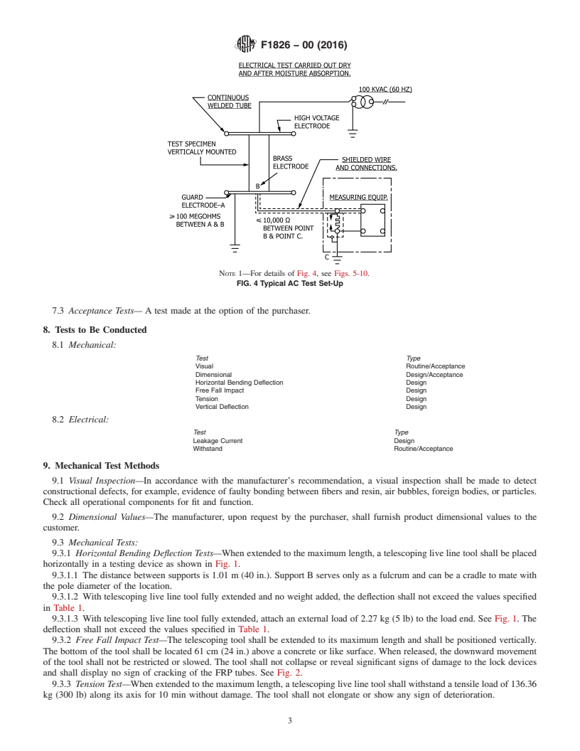
NOTE 1—For details of Fig. 4, see Figs. 5-10.
FIG. 4 Typical AC Test Set-Up
7.3 Acceptance Tests— A test made at the option of the purchaser.
8. Tests to Be Conducted
8.1 Mechanical:
Test Type
Visual Routine/Acceptance
Dimensional Design/Acceptance
Horizontal Bending Deflection Design
Free Fall Impact Design
Tension Design
Vertical Deflection Design
8.2 Electrical:
Test Type
Leakage Current Design
Withstand Routine/Acceptance
9. Mechanical Test Methods
9.1 Visual Inspection—In accordance with the manufacturer’s recommendation, a visual inspection shall be made to detect
constructional defects, for example, evidence of faulty bonding between fibers and resin, air bubbles, foreign bodies, or particles.
Check all operational components for fit and function.
9.2 Dimensional Values—The manufacturer, upon request by the purchaser, shall furnish product dimensional values to the
customer.
9.3 Mechanical Tests:
9.3.1 Horizontal Bending Deflection Tests—When extended to the maximum length, a telescoping live line tool shall be placed
horizontally in a testing device as shown in Fig. 1.
9.3.1.1 The distance between supports is 1.01 m (40 in.). Support B serves only as a fulcrum and can be a cradle to mate with
the pole diameter of the location.
9.3.1.2 With telescoping live line tool fully extended and no weight added, the deflection shall not exceed the values specified
in Table 1.
9.3.1.3 With telescoping live line tool fully extended, attach an external load of 2.27 kg (5 lb) to the load end. See Fig. 1. The
deflection shall not exceed the values specified in Table 1.
9.3.2 Free Fall Impact Test—The telescoping tool shall be extended to its maximum length and shall be positioned vertically.
The bottom of the tool shall be located 61 cm (24 in.) above a concrete or like surface. When released, the downward movement
of the tool shall not be restricted or slowed. The tool shall not collapse or reveal significant signs of damage to the lock devices
and shall display no sign of cracking of the FRP tubes. See Fig. 2.
9.3.3 Tension Test—When extended to the maximum length, a telescoping live line tool shall withstand a tensile load of 136.36
kg (300 lb) along its axis for 10 min without damage. The tool shall not elongate or show any sign of deterioration.
F1826 − 00 (2016)
FIG. 5 Assembly Detail
FIG. 6 Electrode Detail
9.3.4 Vertical Deflection Test—The telescoping live line tool shall be placed vertically in a testing device such that the bottom
section can be tilted. See Fig. 3. The tilt shall be 30.48 cm (12 in.) from vertical at 152 cm (60 in.) from the bottom of the tool.
Without additional restraint, the deflection D at the top of the fully extended tool shall not exceed the values given in Table 2.
10. Electrical Design Test Specimen Preparation
10.1 Three telescoping tools shall each have a specimen cut from each telescoping section. Each specimen shall be 300 mm (12
in.) in length.
10.2 Conditioning Prior to Electrical Tests:
F1826 − 00 (2016)
FIG. 7 Electrode Cap Detail
FIG. 8 Brass Electrode Detail
10.2.1 Prior to the first or initial electrical test, the sample shall be cleaned inside and out with a suitable solvent, as
recommended by the manufacturer, specifica
...
Questions, Comments and Discussion
Ask us and Technical Secretary will try to provide an answer. You can facilitate discussion about the standard in here.