


ASTM G49-85(2011)
(Practice)Standard Practice for Preparation and Use of Direct Tension Stress-Corrosion Test Specimens
Standard Practice for Preparation and Use of Direct Tension Stress-Corrosion Test Specimens
SIGNIFICANCE AND USE
Axially loaded tension specimens provide one of the most versatile methods of performing a stress-corrosion test because of the flexibility permitted in the choice of type and size of test specimen, stressing procedures, and range of stress levels.
The uniaxial stress system is simple; hence, this test method is often used for studies of stress-corrosion mechanisms. This type of test is amenable to the simultaneous exposure of unstressed specimens (no applied load) with stressed specimens and subsequent tension testing to distinguish between the effects of true stress corrosion and mechanical overload (2). Additional considerations in regard to the significance of the test results and their interpretation are given in Sections 6 and 10.
Wide variations in test results may be obtained for a given material and specimen orientation with different specimen sizes and stressing procedures. This consideration is significant especially in the standardization of a test procedure for interlaboratory comparisons or quality control.
SCOPE
1.1 This practice covers procedures for designing, preparing, and using ASTM standard tension test specimens for investigating susceptibility to stress-corrosion cracking. Axially loaded specimens may be stressed quantitatively with equipment for application of either a constant load, constant strain, or with a continuously increasing strain.
1.2 Tension test specimens are adaptable for testing a wide variety of product forms as well as parts joined by welding, riveting, or various other methods.
1.3 The exposure of specimens in a corrosive environment is treated only briefly because other standards are being prepared to deal with this aspect. Meanwhile, the investigator is referred to Practices G35, G36, G37, and G44, and to ASTM Special Technical Publication 425 (1).
General Information
Standards Content (Sample)
NOTICE: This standard has either been superseded and replaced by a new version or withdrawn.
Contact ASTM International (www.astm.org) for the latest information
Designation: G49 − 85 (Reapproved 2011)
Standard Practice for
Preparation and Use of Direct Tension Stress-Corrosion
Test Specimens
ThisstandardisissuedunderthefixeddesignationG49;thenumberimmediatelyfollowingthedesignationindicatestheyearoforiginal
adoption or, in the case of revision, the year of last revision.Anumber in parentheses indicates the year of last reapproval.Asuperscript
epsilon (´) indicates an editorial change since the last revision or reapproval.
1. Scope 3. Summary of Practice
1.1 This practice covers procedures for designing, 3.1 This practice covers the use of axially loaded, quantita-
preparing,andusingASTMstandardtensiontestspecimensfor tively stressed ASTM standard tension test specimens for
investigating susceptibility to stress-corrosion cracking. Axi- investigating the resistance to stress-corrosion cracking of
ally loaded specimens may be stressed quantitatively with metallic materials in all types of product forms. Consideration
equipment for application of either a constant load, constant is given to important factors in the selection of appropriate
strain, or with a continuously increasing strain. specimens, the design of loading equipment, and the effects of
these factors on the state of stress in the specimen as corrosion
1.2 Tension test specimens are adaptable for testing a wide
occurs.
variety of product forms as well as parts joined by welding,
riveting, or various other methods.
4. Significance and Use
1.3 The exposure of specimens in a corrosive environment
4.1 Axially loaded tension specimens provide one of the
is treated only briefly because other standards are being
most versatile methods of performing a stress-corrosion test
prepared to deal with this aspect. Meanwhile, the investigator
because of the flexibility permitted in the choice of type and
is referred to Practices G35, G36, G37, and G44, and toASTM
2 size of test specimen, stressing procedures, and range of stress
Special Technical Publication 425 (1).
levels.
2. Referenced Documents 4.2 The uniaxial stress system is simple; hence, this test
3 method is often used for studies of stress-corrosion mecha-
2.1 ASTM Standards:
nisms. This type of test is amenable to the simultaneous
E8 Test Methods for Tension Testing of Metallic Materials
exposure of unstressed specimens (no applied load) with
G35 Practice for Determining the Susceptibility of Stainless
stressed specimens and subsequent tension testing to distin-
Steels and Related Nickel-Chromium-Iron Alloys to
guish between the effects of true stress corrosion and mechani-
Stress-Corrosion Cracking in Polythionic Acids
cal overload (2). Additional considerations in regard to the
G36 Practice for Evaluating Stress-Corrosion-Cracking Re-
significance of the test results and their interpretation are given
sistance of Metals and Alloys in a Boiling Magnesium
in Sections 6 and 10.
Chloride Solution
G37 Practice for Use of Mattsson’s Solution of pH 7.2 to 4.3 Wide variations in test results may be obtained for a
Evaluate the Stress-Corrosion Cracking Susceptibility of given material and specimen orientation with different speci-
Copper-Zinc Alloys men sizes and stressing procedures. This consideration is
G44 PracticeforExposureofMetalsandAlloysbyAlternate significant especially in the standardization of a test procedure
Immersion in Neutral 3.5 % Sodium Chloride Solution for interlaboratory comparisons or quality control.
5. Test Specimens
This practice is under the jurisdiction of ASTM Committee G01 on Corrosion
5.1 Whenever possible, tension test specimens used in
of Metals and is the direct responsibility of Subcommittee G01.06 on Environmen-
evaluating susceptibility to stress-corrosion cracking should
tally Assisted Cracking.
conform to the dimensions of standard tension test specimens
Current edition approved March 1, 2011. Published April 2011. Originally
approved in 1976. Last previous edition approved in 2005 as G49–85(2005). DOI:
specified in Test Methods E8, which contain details for
10.1520/G0049-85R11.
specimens machined from various product forms.
The boldface numbers in parentheses refer to a list of references at the end of
this standard.
5.2 A wide range of sizes for tension test specimens is
For referenced ASTM standards, visit the ASTM website, www.astm.org, or
possible, depending primarily upon the dimensions of the
contact ASTM Customer Service at service@astm.org. For Annual Book of ASTM
product to be tested. Because the stress-corrosion test results
Standards volume information, refer to the standard’s Document Summary page on
the ASTM website. can be markedly influenced by the cross section of the test
Copyright © ASTM International, 100 Barr Harbor Drive, PO Box C700, West Conshohocken, PA 19428-2959. United States
G49 − 85 (2011)
specimen, this factor should be given careful consideration
with regard to the object of the investigation. Although larger
specimens may be more representative of most actual
structures, they often cannot be machined from product forms
to be evaluated; and they present more difficulties in stressing
and handling in the laboratory.Also, larger specimens of some
materials may require longer exposure periods than smaller
specimens.
5.3 Smaller cross-section specimens are widely used be-
cause they (1) have a greater sensitivity to the initiation of
stress-corrosion cracking, (2) usually give test results more
quickly, and (3) permit greater convenience in testing. On the
other hand, the smaller specimens are more difficult to
machine, and their performance is more likely to be influenced
by extraneous stress concentrations resulting from non-axial
loading, corrosion pits, etc. Therefore, specimens less than
about 10 mm (0.4 in.) in gauge length or 3.0 mm (0.12 in.) in
diameter are not recommended for general use.
5.4 Tension specimens containing machined notches have
been used in studies of stress-corrosion cracking and hydrogen
embrittlement (3). The presence of a notch induces a triaxial
stressstateattherootofthenotchwhereintheactualstresswill
be greater by a concentration factor dependent on the notch
geometry.Advantages of such specimens include the probable
localization of cracking to the notch region and acceleration of
failure. However, unless directly related to practical conditions
NOTE 1—The behavior shown is generally representative, but the
of usage, spurious results may ensue.
curves will vary with specific alloys and tempers.
5.5 Tension specimens containing a machined notch in
FIG. 1 Effect of Loading Method and Extent of Cracking or Corro-
which a mechanical precrack (for example, a fatigue or tension sion Pattern on Average Net Section Stress
crack) has been started will be the subject of another ASTM
standard. Various types of precracked specimens are discussed
stress becomes greater than the nominal gross section stress
in other publications (2, 4).
and increases to the point of fracture, either of two events can
occur: (1) fracture by mechanical overload of a material that is
6. Stress Considerations
not susceptible to stress-corrosion cracking, or (2) stress-
6.1 There are several factors that may introduce bending
corrosion cracking of a material at an unknown stress higher
moments on specimens, such as a longitudinal curvature,
than the intended nominal test stress. The occurrence of either
misalignmentofthreadsonthreaded-endroundspecimens,and
of these phenomena would interfere with a valid evaluation of
the corners of sheet-type specimens. The significance of these
materials with a relatively high resistance to stress corrosion.
factors is greater for specimens with smaller cross sections.
These considerations must be taken into account in experi-
Even though eccentricity in loading can be minimized to equal
ments undertaken to determine “threshold” stresses. The sig-
the same standards accepted for tension testing machines,
nificance of these factors is discussed further in Section 10.
inevitably, there is some variation in the tensile stress around
the circumference of the test specimen which can be of such 7. Stressing Methods
magnitude that it will introduce considerable error in the
7.1 General Considerations:
desired stress. Tests should be made on specimens with strain
7.1.1 Tension specimens may be subjected to a wide range
gages affixed to the specimen surface (around the circumfer-
of stress levels associated with either elastic or elastic and
ence in 90° or 120° intervals) to verify strain and stress
plastic strain. Because the stress system is intended to be
uniformity and determine if machining practices and stressing
essentially uniaxial (except in the case of notched specimens),
jigs are of adequate tolerance and quality.
great care must be exercised in the construction of stressing
6.2 Another consideration is the possible increase in net frames so that bending stresses are avoided or minimized.
section stress that will occur when corrosion develops during 7.1.2 Although a number of different stressing frames have
the environmental exposure (1, 5). As shown schematically in been used with tension specimens, three basic types are
Fig. 1, there are two limiting curves: one for zero stiffness considered herein: constant (sustained) load, constant strain
(dead weight) and the other for infinite stiffness (ideal constant (deformation), and continuously increasing strain. A constant
strain). In actual testing with various types of stressing frames, loadcanbeobtainedwithdeadweight,buttrulyconstantstrain
such as those shown in Figs. 2-4, the increase in net section loading is seldom achieved because a stressing frame with
stress will be somewhere in between. When the net section infinitestiffnesswouldberequired.Stress-corrosiontestresults
G49 − 85 (2011)
FIG. 2 Spring-Loaded Stressing Frame (6)
more practical. The advantage of any dead-weight loading
device is the constancy of the applied load.
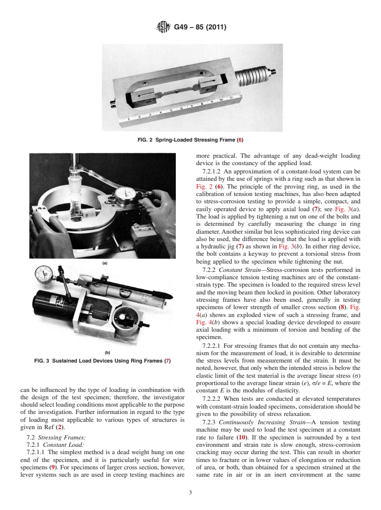
7.2.1.2 An approximation of a constant-load system can be
attained by the use of springs with a ring such as that shown in
Fig. 2 (6). The principle of the proving ring, as used in the
calibration of tension testing machines, has also been adapted
to stress-corrosion testing to provide a simple, compact, and
easily operated device to apply axial load (7); see Fig. 3(a).
The load is applied by tightening a nut on one of the bolts and
is determined by carefully measuring the change in ring
diameter.Anothersimilarbutlesssophisticatedringdevicecan
also be used, the difference being that the load is applied with
a hydraulic jig (7) as shown in Fig. 3(b). In either ring device,
the bolt contains a keyway to prevent a torsional stress from
being applied to the specimen while tightening the nut.
7.2.2 Constant Strain—S
...
Questions, Comments and Discussion
Ask us and Technical Secretary will try to provide an answer. You can facilitate discussion about the standard in here.