


ASTM E1767-11(2017)
(Practice)Standard Practice for Specifying the Geometries of Observation and Measurement to Characterize the Appearance of Materials
Standard Practice for Specifying the Geometries of Observation and Measurement to Characterize the Appearance of Materials
SIGNIFICANCE AND USE
5.1 This practice is for the use of manufacturers and users of equipment for visual appraisal or measurement of appearance, those writing standards related to such equipment, and others who wish to specify precisely conditions of viewing or measuring attributes of appearance. The use of this practice makes such specifications concise and unambiguous. The functional notation facilitates direct comparisons of the geometric specifications of viewing situations and measuring instruments.
SCOPE
1.1 This practice describes the geometry of illuminating and viewing specimens and the corresponding geometry of optical measurements to characterize the appearance of materials. It establishes terms, symbols, a coordinate system, and functional notation to describe the geometric orientation of a specimen, the geometry of the illumination (or optical irradiation) of a specimen, and the geometry of collection of flux reflected or transmitted by the specimen, by a measurement standard, or by the open sampling aperture.
1.2 Optical measurements to characterize the appearance of retroreflective materials are of such a special nature that they are treated in other ASTM standards and are excluded from the scope of this practice.
1.3 The measurement of transmitted or reflected light from areas less than 0.5 mm in diameter may be affected by optical coherence, so measurements on such small areas are excluded from consideration in this practice, although the basic concepts described in this practice have been adopted in that field of measurement.
1.4 The specification of a method of measuring the reflecting or transmitting properties of specimens, for the purpose of characterizing appearance, is incomplete without a full description of the spectral nature of the system, but spectral conditions are not within the scope of this practice. The use of functional notation to specify spectral conditions is described in ISO 5/1.
1.5 This standard does not purport to address all of the safety concerns, if any, associated with its use. It is the responsibility of the user of this standard to establish appropriate safety, health, and environmental practices and determine the applicability of regulatory limitations prior to use.
1.6 This international standard was developed in accordance with internationally recognized principles on standardization established in the Decision on Principles for the Development of International Standards, Guides and Recommendations issued by the World Trade Organization Technical Barriers to Trade (TBT) Committee.
General Information
Buy Standard
Standards Content (Sample)
NOTICE: This standard has either been superseded and replaced by a new version or withdrawn.
Contact ASTM International (www.astm.org) for the latest information
Designation: E1767 − 11 (Reapproved 2017)
Standard Practice for
Specifying the Geometries of Observation and Measurement
to Characterize the Appearance of Materials
This standard is issued under the fixed designation E1767; the number immediately following the designation indicates the year of
original adoption or, in the case of revision, the year of last revision. A number in parentheses indicates the year of last reapproval. A
superscript epsilon (´) indicates an editorial change since the last revision or reapproval.
INTRODUCTION
The appearance of objects depends on how they are illuminated and viewed. When measurements
are made to characterize appearance attributes such as color or gloss, the measured values depend on
the geometry of the illumination and the instrumentation receiving light from the specimen. This
practice for specifying the geometry in such applications is largely based on an international standard
ISO 5/1, dealing with the precise measurement of optical density in photographic science, based on
2,3
an earlier American National Standard.
1. Scope are not within the scope of this practice. The use of functional
notation to specify spectral conditions is described in ISO 5/1.
1.1 This practice describes the geometry of illuminating and
1.5 This standard does not purport to address all of the
viewing specimens and the corresponding geometry of optical
safety concerns, if any, associated with its use. It is the
measurements to characterize the appearance of materials. It
responsibility of the user of this standard to establish appro-
establishes terms, symbols, a coordinate system, and functional
priate safety, health, and environmental practices and deter-
notation to describe the geometric orientation of a specimen,
mine the applicability of regulatory limitations prior to use.
the geometry of the illumination (or optical irradiation) of a
1.6 This international standard was developed in accor-
specimen, and the geometry of collection of flux reflected or
dance with internationally recognized principles on standard-
transmitted by the specimen, by a measurement standard, or by
ization established in the Decision on Principles for the
the open sampling aperture.
Development of International Standards, Guides and Recom-
1.2 Optical measurements to characterize the appearance of
mendations issued by the World Trade Organization Technical
retroreflective materials are of such a special nature that they
Barriers to Trade (TBT) Committee.
are treated in otherASTM standards and are excluded from the
scope of this practice.
2. Referenced Documents
1.3 The measurement of transmitted or reflected light from
2.1 ASTM Standards:
areas less than 0.5 mm in diameter may be affected by optical
E284 Terminology of Appearance
coherence, so measurements on such small areas are excluded
2.2 Other Standard:
from consideration in this practice, although the basic concepts
ISO 5/1 Photography—Density Measurements—Part 1:
described in this practice have been adopted in that field of
Terms, Symbols and Notations
measurement.
1.4 The specification of a method of measuring the reflect-
3. Terminology
ing or transmitting properties of specimens, for the purpose of
3.1 Definitions:
characterizingappearance,isincompletewithoutafulldescrip-
3.1.1 The terminology used in this practice is in accordance
tion of the spectral nature of the system, but spectral conditions
with Terminology E284.
3.2 Definitions of Terms Specific to This Standard:
This practice is under the jurisdiction of ASTM Committee E12 on Color and
Appearance and is the direct responsibility of Subcommittee E12.03 on Geometry.
Current edition approved Nov. 1, 2017. Published November 2017. Originally
approved in 1995. Last previous edition approved in 2011 as E1767 – 11. DOI: For referenced ASTM standards, visit the ASTM website, www.astm.org, or
10.1520/E1767-11R17. contact ASTM Customer Service at service@astm.org. For Annual Book of ASTM
ISO1/5 Photograhpy — Density Measurements — Part 1: Terms, symbols, and Standards volume information, refer to the standard’s Document Summary page on
notations. the ASTM website.
3 5
ANSIPH2.36–1974AmericanNationalStandardsterms,symbols,andnotation Available from American National Standards Institute (ANSI), 25 W. 43rd St.,
for optical transmission and reflection measurements. 4th Floor, New York, NY 10036, http://www.ansi.org.
Copyright © ASTM International, 100 Barr Harbor Drive, PO Box C700, West Conshohocken, PA 19428-2959. United States
E1767 − 11 (2017)
3.2.1 anormal angle, n—an angle measured from the 3.2.16 uniplanar geometry, n—geometry in which the re-
normal, toward the reference plane, to the central axis of a ceiver is in the plane of incidence.
distribution, which may be an angular distribution of flux in an
3.3 Symbols:
incident beam or distribution of sensitivity of a receiver.
3.2.2 aspecular angle, n—the angle subtended at the origin
de = general symbol for diffuse geometry with specular
by the specular axis and the axis of the receiver, the positive
component excluded.
direction being away from the specular axis.
di = general symbol for diffuse geometry with specular
3.2.3 aspecular azimuthal angle, n—the angle subtended, at
component included.
the specular axis in a plane normal to the specular axis, by the
E = identifies the direction of the axis of an efflux
projection of the axis of the receiver and the projection of the
distribution on a diagram.
x-axis on that plane, measured from the projection of the x-axis
g = general symbol, in functional notation, for efflux
in a right-handed sense with respect to the specular axis.
geometry.
3.2.4 efflux, n—radiant flux reflected by a specimen or G = general symbol, in functional notation, for influx
geometry.
reflection standard, in the case of reflection observations or
i = subscript for incident.
measurements, or transmitted by a specimen or open sampling
I = identifies the direction of the axis of an influx
aperture, in the case of transmission observations or
distribution on a diagram.
measurements, in the direction of the receiver.
m = subscript for half cone angle subtended by the
3.2.5 efflux, adj—associated with the radiant flux reflected
entrance pupil of a test photometer.
by a specimen or reflection standard, in the case of reflection
M = optical modulation.
observations or measurements, or transmitted by a specimen or
n = subscript for half cone angle subtended by a test
open sampling aperture, in the case of transmission observa-
source.
tions or measurements, in the direction of the receiver.
N = identifies the direction of the normal to the reference
3.2.6 efflux region, n—region in the reference plane from
plane on a diagram.
o = point of origin of a rectangular coordinate system, in
which flux is sensed by the observer.
the reference plane, at the center or centroid of the
3.2.7 influx, n—radiant flux received from the illuminator at
sampling aperture.
a specimen, a reflection standard, or open sampling aperture.
r = subscript for reflected.
3.2.8 influx, adj—associated with radiant flux received from
S = identifies the specular direction on a diagram.
the illuminator at a specimen, a reflection standard, or open
t = subscript for transmitted.
sampling aperture.
x = distance from the origin, along the x-axis, in the
reference plane, passing through point o.
3.2.9 influx region, n—region in the reference plane on
y = distance from the origin, along the y-axis, in the
which flux is incident.
reference plane, passing through point o, and normal
3.2.10 optical modulation, n—a ratio indicating the magni-
to the x-axis.
tude of the propagation by a specimen of radiant flux from a
z = distance from the origin, along the z-axis, normal to
specified illuminator or irradiator to a specified receiver, a
the reference plane, passing through point o, and
general term for reflectance, transmittance, reflectance factor,
having its positive direction in the direction of the
transmittance factor, or radiance factor.
vector component of incident flux normal to the
3.2.11 plane of incidence, n—the plane containing the axis
reference plane.
of the incident beam and the normal to the reference plane.
α = aspecular angle.
3.2.11.1 Discussion—This plane is not defined if the axis of
β = aspecular azimuthal angle.
the incident beam is normal to the reference plane. δ = in a pyramidal distribution, the half-angle measured
in the direction normal to the plane of incidence.
3.2.12 reference plane, n—the plane in which the surface of
ε = in a pyramidal distribution, the half-angle measured
a plane specimen is placed for observation or measurement, or
in the plane of incidence.
in the case of a nonplanar specimen, the plane with respect to
η = azimuthal angle, measured in the reference plane,
which the measurement is made.
from the positive x-axis, in the direction of the
3.2.13 sampling aperture, n—the region in the reference
positive y-axis.
plane on which a measurement is made, the intersection of the
θ = anormal angle.
influx region and the efflux region.
κ = half cone angle of a conical flux distribution.
Φ = radiant flux
3.2.14 specular axis, n—the ray resulting from specular
45°a = general symbol for 45° annular geometry
reflection at an ideal plane mirror in the reference plane, of the
45°c = general symbol for 45° circumferential geometry
ray at the geometric axis of the incident beam.
3.2.14.1 Discussion—This term is applied to an incident
4. Summary of Practice
beam subtending a small angle at the origin, not to diffuse or
annular illuminators.
4.1 This practice provides a method of specifying the
3.2.15 specular direction, n—the direction of the specular geometry of illuminating and viewing a material or the
axis, the positive direction being away from the origin. geometry of instrumentation for measuring an attribute of
E1767 − 11 (2017)
appearance. In general, for measured values to correlate well to the following rules, intended to place the positive x-axis in
with appearance, the geometric conditions of measurement the azimuthal direction for which the product of illumination
must simulate the conditions of viewing. and receiver sensitivity is a minimum.
6.2.1 For an integrating-sphere instrument with diffuse
5. Significance and Use
illumination, the positive x-axis is directed toward the projec-
5.1 Thispracticeisfortheuseofmanufacturersandusersof tion of the center of the exit port on the reference plane.
equipment for visual appraisal or measurement of appearance, 6.2.2 For an integrating-sphere instrument with diffuse
those writing standards related to such equipment, and others
collection, the positive x-axis is directed toward the projection
who wish to specify precisely conditions of viewing or of the center of the entrance port on the reference plane.
measuring attributes of appearance. The use of this practice
6.2.3 For an instrument with annular (circumferential)
makes such specifications concise and unambiguous. The
45°:0° or 0°:45° geometry, the positive x-axis is in the
functional notation facilitates direct comparisons of the geo-
azimuthal direction for which the product of illumination and
metric specifications of viewing situations and measuring
receiver sensitivity is a minimum.
instruments.
6.2.4 For an instrument with highly directional illumination,
off the normal, such as is used in the measurement of gloss or
6. Coordinate System
goniochromatism, the positive x-axis is directed along the
6.1 The standard coordinate system is illustrated in Fig. 1.It
projection of the specular direction on the reference plane.
is a left-handed rectangular coordinate system, following the
6.3 Anormal angles are specified with respect to rays
usual optical convention of incident and transmitted flux in the
passing through the origin. (In a later section of this standard,
positive direction and the usual convention for the orientation
allowance is made for the size of the sampling aperture by the
of x and y for the reflection case. The coordinates are related to
tolerances on the influx and efflux angles.) Anormal angles of
a reference plane in which the first surface of the specimen is
incident and reflected rays are measured from the negative
placed for observation or measurement. The origin is in the
z-axis. Anormal angles of transmitted rays are measured from
reference plane at the center or centroid of the sampling
the positive z-axis.
aperture.
6.4 The azimuthal angle of a ray is the angle η, measured in
6.2 Instruments are usually designed to minimize the varia-
the reference plane from the positive x-axis in the direction of
tion of the product of illumination and receiver sensitivity, as a
the positive y-axis, to the projection of the ray on the reference
function of the azimuthal direction. That practice minimizes
plane. The direction of a ray is given by θ and η, in that order.
the variation in modulation as the specimen is rotated in its
Angleη is less than 360° andθ is 180° or less, and usually less
own plane. Even in instruments with an integrating sphere,
than 90°.
residualvariationoftheproduct,knownas“directionality,”can
cause variations in measurements of textured specimens ro- 6.5 In gonioradiometry and goniospectrometry, the efflux
tated in their plane. To minimize variation among routine angle θ or θ may be measured from the normal, but for
r t
product measurements due to this effect, the “warp,” “grain,” reflection measurements to characterize goniochromatism, it is
orother“machinedirection”ofspecimensmustbeconsistently
often measured from the specular axis. The aspecular angle α
oriented with respect to the x-axis, which is directed according is the angle subtended at the origin by the specular axis and the
FIG. 1 Coordinate System for Describing the Geometric Factors Affecting Transmission and Reflection Measures
E1767 − 11 (2017)
axis of the receiver. In most gonioradiometric measurements, may be very complicated. Fortunately, most such distributions
the axis of the receiver is in the plane of incidence and the in instruments used to measure appearance can be approxi-
aspecular angle is measured in that plane. In that case, the mated by uniform pencils bounded by right circular cones. The
positive direction ofα is from the specular direction toward the eye, the receiver in the case of visual observation, may be
normal. described in this way. In such cases, the description can be
relatively simple. For this purpose, the direction of the axis of
6.6 Iftheaxisofthereceiverisnotintheplaneofincidence,
the cone is given by θ and η and the half cone angle is given
the direction of the axis may be described in terms of anormal
the symbol κ. Th
...
This document is not an ASTM standard and is intended only to provide the user of an ASTM standard an indication of what changes have been made to the previous version. Because
it may not be technically possible to adequately depict all changes accurately, ASTM recommends that users consult prior editions as appropriate. In all cases only the current version
of the standard as published by ASTM is to be considered the official document.
Designation: E1767 − 11 E1767 − 11 (Reapproved 2017)
Standard Practice for
Specifying the Geometries of Observation and Measurement
to Characterize the Appearance of Materials
This standard is issued under the fixed designation E1767; the number immediately following the designation indicates the year of
original adoption or, in the case of revision, the year of last revision. A number in parentheses indicates the year of last reapproval. A
superscript epsilon (´) indicates an editorial change since the last revision or reapproval.
INTRODUCTION
The appearance of objects depends on how they are illuminated and viewed. When measurements
are made to characterize appearance attributes such as color or gloss, the measured values depend on
the geometry of the illumination and the instrumentation receiving light from the specimen. This
practice for specifying the geometry in such applications is largely based on an international standard
ISO 5/1, dealing with the precise measurement of optical density in photographic science, based on
2,3
an earlier American National Standard.
1. Scope
1.1 This practice describes the geometry of illuminating and viewing specimens and the corresponding geometry of optical
measurements to characterize the appearance of materials. It establishes terms, symbols, a coordinate system, and functional
notation to describe the geometric orientation of a specimen, the geometry of the illumination (or optical irradiation) of a specimen,
and the geometry of collection of flux reflected or transmitted by the specimen, by a measurement standard, or by the open
sampling aperture.
1.2 Optical measurements to characterize the appearance of retroreflective materials are of such a special nature that they are
treated in other ASTM standards and are excluded from the scope of this practice.
1.3 The measurement of transmitted or reflected light from areas less than 0.5 mm in diameter may be affected by optical
coherence, so measurements on such small areas are excluded from consideration in this practice, although the basic concepts
described in this practice have been adopted in that field of measurement.
1.4 The specification of a method of measuring the reflecting or transmitting properties of specimens, for the purpose of
characterizing appearance, is incomplete without a full description of the spectral nature of the system, but spectral conditions are
not within the scope of this practice. The use of functional notation to specify spectral conditions is described in ISO 5/1.
1.5 This standard does not purport to address all of the safety concerns, if any, associated with its use. It is the responsibility
of the user of this standard to establish appropriate safety, health, and environmental practices and determine the applicability of
regulatory limitations prior to use.
1.6 This international standard was developed in accordance with internationally recognized principles on standardization
established in the Decision on Principles for the Development of International Standards, Guides and Recommendations issued
by the World Trade Organization Technical Barriers to Trade (TBT) Committee.
2. Referenced Documents
2.1 ASTM Standards:
E284 Terminology of Appearance
This practice is under the jurisdiction of ASTM Committee E12 on Color and Appearance and is the direct responsibility of Subcommittee E12.03 on Geometry.
Current edition approved Nov. 1, 2011Nov. 1, 2017. Published December 2011November 2017. Originally approved in 1995. Last previous edition approved in 20042011
as E1767 – 04.E1767 – 11. DOI: 10.1520/E1767-11.10.1520/E1767-11R17.
ISO1/5 Photograhpy — Density Measurements — Part 1: Terms, symbols, and notations.
ANSI PH2.36–1974 American National Standards terms, symbols, and notation for optical transmission and reflection measurements.
For referenced ASTM standards, visit the ASTM website, www.astm.org, or contact ASTM Customer Service at service@astm.org. For Annual Book of ASTM Standards
volume information, refer to the standard’s Document Summary page on the ASTM website.
Copyright © ASTM International, 100 Barr Harbor Drive, PO Box C700, West Conshohocken, PA 19428-2959. United States
E1767 − 11 (2017)
2.2 Other Standard:
ISO 5/1 Photography—Density Measurements—Part 1: Terms, Symbols and Notations
3. Terminology
3.1 Definitions:
3.1.1 The terminology used in this practice is in accordance with Terminology E284.
3.2 Definitions of Terms Specific to This Standard:
3.2.1 anormal angle, n—an angle measured from the normal, toward the reference plane, to the central axis of a distribution,
which may be an angular distribution of flux in an incident beam or distribution of sensitivity of a receiver.
3.2.2 aspecular angle, n—the angle subtended at the origin by the specular axis and the axis of the receiver, the positive
direction being away from the specular axis.
3.2.3 aspecular azimuthal angle, n—the angle subtended, at the specular axis in a plane normal to the specular axis, by the
projection of the axis of the receiver and the projection of the x-axis on that plane, measured from the projection of the x-axis in
a right-handed sense with respect to the specular axis.
3.2.4 efflux, n—radiant flux reflected by a specimen or reflection standard, in the case of reflection observations or
measurements, or transmitted by a specimen or open sampling aperture, in the case of transmission observations or measurements,
in the direction of the receiver.
3.2.5 efflux, adj—associated with the radiant flux reflected by a specimen or reflection standard, in the case of reflection
observations or measurements, or transmitted by a specimen or open sampling aperture, in the case of transmission observations
or measurements, in the direction of the receiver.
3.2.6 efflux region, n—region in the reference plane from which flux is sensed by the observer.
3.2.7 influx, n—radiant flux received from the illuminator at a specimen, a reflection standard, or open sampling aperture.
3.2.8 influx, adj—associated with radiant flux received from the illuminator at a specimen, a reflection standard, or open
sampling aperture.
3.2.9 influx region, n—region in the reference plane on which flux is incident.
3.2.10 optical modulation, n—a ratio indicating the magnitude of the propagation by a specimen of radiant flux from a specified
illuminator or irradiator to a specified receiver, a general term for reflectance, transmittance, reflectance factor, transmittance factor,
or radiance factor.
3.2.11 plane of incidence, n—the plane containing the axis of the incident beam and the normal to the reference plane.
3.2.11.1 Discussion—
This plane is not defined if the axis of the incident beam is normal to the reference plane.
3.2.12 reference plane, n—the plane in which the surface of a plane specimen is placed for observation or measurement, or in
the case of a nonplanar specimen, the plane with respect to which the measurement is made.
3.2.13 sampling aperture, n—the region in the reference plane on which a measurement is made, the intersection of the influx
region and the efflux region.
3.2.14 specular axis, n—the ray resulting from specular reflection at an ideal plane mirror in the reference plane, of the ray at
the geometric axis of the incident beam.
3.2.14.1 Discussion—
This term is applied to an incident beam subtending a small angle at the origin, not to diffuse or annular illuminators.
3.2.15 specular direction, n—the direction of the specular axis, the positive direction being away from the origin.
3.2.16 uniplanar geometry, n—geometry in which the receiver is in the plane of incidence.
3.3 Symbols:
de = general symbol for diffuse geometry with specular component excluded.
di = general symbol for diffuse geometry with specular component included.
E = identifies the direction of the axis of an efflux distribution on a diagram.
Available from American National Standards Institute (ANSI), 25 W. 43rd St., 4th Floor, New York, NY 10036, http://www.ansi.org.
E1767 − 11 (2017)
g = general symbol, in functional notation, for efflux geometry.
G = general symbol, in functional notation, for influx geometry.
i = subscript for incident.
I = identifies the direction of the axis of an influx distribution on a diagram.
m = subscript for half cone angle subtended by the entrance pupil of a test photometer.
M = optical modulation.
n = subscript for half cone angle subtended by a test source.
N = identifies the direction of the normal to the reference plane on a diagram.
o = point of origin of a rectangular coordinate system, in the reference plane, at the center or centroid of the sampling
aperture.
r = subscript for reflected.
S = identifies the specular direction on a diagram.
t = subscript for transmitted.
x = distance from the origin, along the x-axis, in the reference plane, passing through point o.
y = distance from the origin, along the y-axis, in the reference plane, passing through point o, and normal to the x-axis.
z = distance from the origin, along the z-axis, normal to the reference plane, passing through point o, and having its positive
direction in the direction of the vector component of incident flux normal to the reference plane.
α = aspecular angle.
β = aspecular azimuthal angle.
δ = in a pyramidal distribution, the half-angle measured in the direction normal to the plane of incidence.
ε = in a pyramidal distribution, the half-angle measured in the plane of incidence.
η = azimuthal angle, measured in the reference plane, from the positive x-axis, in the direction of the positive y-axis.
θ = anormal angle.
κ = half cone angle of a conical flux distribution.
Φ = radiant flux
45°a = general symbol for 45° annular geometry
45°c = general symbol for 45° circumferential geometry
4. Summary of Practice
4.1 This practice provides a method of specifying the geometry of illuminating and viewing a material or the geometry of
instrumentation for measuring an attribute of appearance. In general, for measured values to correlate well with appearance, the
geometric conditions of measurement must simulate the conditions of viewing.
5. Significance and Use
5.1 This practice is for the use of manufacturers and users of equipment for visual appraisal or measurement of appearance,
those writing standards related to such equipment, and others who wish to specify precisely conditions of viewing or measuring
attributes of appearance. The use of this practice makes such specifications concise and unambiguous. The functional notation
facilitates direct comparisons of the geometric specifications of viewing situations and measuring instruments.
6. Coordinate System
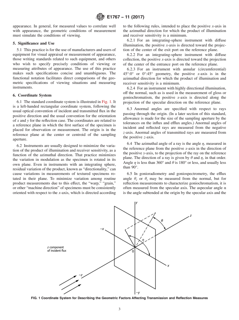
6.1 The standard coordinate system is illustrated in Fig. 1. It is a left-handed rectangular coordinate system, following the usual
optical convention of incident and transmitted flux in the positive direction and the usual convention for the orientation of x and
y for the reflection case. The coordinates are related to a reference plane in which the first surface of the specimen is placed for
observation or measurement. The origin is in the reference plane at the center or centroid of the sampling aperture.
6.2 Instruments are usually designed to minimize the variation of the product of illumination and receiver sensitivity, as a
function of the azimuthal direction. That practice minimizes the variation in modulation as the specimen is rotated in its own plane.
Even in instruments with an integrating sphere, residual variation of the product, known as “directionality,” can cause variations
in measurements of textured specimens rotated in their plane. To minimize variation among routine product measurements due to
this effect, the “warp,” “grain,” or other “machine direction” of specimens must be consistently oriented with respect to the x-axis,
which is directed according to the following rules, intended to place the positive x-axis in the azimuthal direction for which the
product of illumination and receiver sensitivity is a minimum.
6.2.1 For an integrating-sphere instrument with diffuse illumination, the positive x-axis is directed toward the projection of the
center of the exit port on the reference plane.
6.2.2 For an integrating-sphere instrument with diffuse collection, the positive x-axis is directed toward the projection of the
center of the entrance port on the reference plane.
6.2.3 For an instrument with annular (circumferential) 45°:0° or 0°:45° geometry, the positive x-axis is in the azimuthal
direction for which the product of illumination and receiver sensitivity is a minimum.
6.2.4 For an instrument with highly directional illumination, off the normal, such as is used in the measurement of gloss or
goniochromatism, the positive x-axis is directed along the projection of the specular direction on the reference plane.
E1767 − 11 (2017)
FIG. 1 Coordinate System for Describing the Geometric Factors Affecting Transmission and Reflection Measures
6.3 Anormal angles are specified with respect to rays passing through the origin. (In a later section of this standard, allowance
is made for the size of the sampling aperture by the tolerances on the influx and efflux angles.) Anormal angles of incident and
reflected rays are measured from the negative z-axis. Anormal angles of transmitted rays are measured from the positive z-axis.
6.4 The azimuthal angle of a ray is the angle η, measured in the reference plane from the positive x-axis in the direction of the
positive y-axis, to the projection of the ray on the reference plane. The direction of a ray is given by θ and η, in that order. Angle
η is less than 360° and θ is 180° or less, and usually less than 90°.
6.5 In gonioradiometry and goniospectrometry, the efflux angle θ or θ may be measured from the normal, but for reflection
r t
measurements to characterize goniochromatism, it is often measured from the specular axis. The aspecular angle α is the angle
subtended at the origin by the specular axis and the axis of the receiver. In most gonioradiometric measurements, the axis of the
receiver is in the plane of incidence and the aspecular angle is measured in that plane. In that case, the positive direction of α is
from the specular direction toward the normal.
6.6 If the axis of the receiver is not in the plane of incidence, the direction of the axis may be described in terms of anormal
and azimuthal angles, as defined in 6.5, but an aspecular azimuthal a
...
Questions, Comments and Discussion
Ask us and Technical Secretary will try to provide an answer. You can facilitate discussion about the standard in here.