


ASTM F1957-99(2011)
(Test Method)Standard Test Method for Composite Foam Hardness-Durometer Hardness
Standard Test Method for Composite Foam Hardness-Durometer Hardness
SIGNIFICANCE AND USE
This test method is based on the penetration by a specific type of indentor when forced into the material under specified conditions. The indentation hardness is related inversely to the penetration and is dependent on the elastic modulus and viscoelastic behavior of the material. The geometry of the indentor and the applied force influence the measurements, such that no simple relationship exists between the measurements obtained with one type of durometer and those obtained with another type of durometer or other instruments used for measuring hardness. This test method is an empirical test intended primarily for control purposes. No simple relationship exists between indentation hardness determined by this test method and any fundamental property of the material tested. For specification purposes it is recommended that Test Method D785 be used for hard materials and Test Method D2240 be used for solid elatomers.
SCOPE
1.1 This test method describes a type of composite foam hardness measurement device known as durometer: Type CF. The procedure for determining indentation hardness of substances comprised of two or more elastomeric materials, one of which is a foam or foam like material. These are classified as composite foam structures. The composite foam product may have an armature made of a material suitable for adding structural integrity including but not limited to metal, plastic, or wood. This construction is typical for lapbar restraints, seating, and other restraint devices, as well as some show elements.
1.2 This test method is not equivalent to other indentation hardness methods and instrument types, specifically those described in Test Methods D1415 and D2240.
1.3 The values stated in SI units are to be regarded as standard. The values given in parentheses are for information only. Many of the stated dimensions in SI are direct conversions from the U.S. customary system to accommodate the instrumentation, practices, and procedures that existed prior to the Metric Conversion Act of 1975.
1.4 All materials, instruments, or equipment used for the determination of mass or dimension shall have traceability to the National Institute for Standards and Technology (NIST) or other internationally recognized organizations.
1.5 This test method is not a safety standard as it pertains to ride legislation. The use of this test method is optional based upon an agreement between customers and suppliers of foam products.
1.6 This standard does not purport to address all of the safety concerns, if any, associated with its use. It is the responsibility of the user of this standard to establish appropriate safety and health practices and determine the applicability of regulatory limitations prior to use.
General Information
Buy Standard
Standards Content (Sample)
NOTICE: This standard has either been superseded and replaced by a new version or withdrawn.
Contact ASTM International (www.astm.org) for the latest information
Designation: F1957 − 99 (Reapproved 2011)
Standard Test Method for
Composite Foam Hardness-Durometer Hardness
This standard is issued under the fixed designation F1957; the number immediately following the designation indicates the year of
original adoption or, in the case of revision, the year of last revision.Anumber in parentheses indicates the year of last reapproval.A
superscript epsilon (´) indicates an editorial change since the last revision or reapproval.
1. Scope 2. Referenced Documents
2.1 ASTM Standards:
1.1 This test method describes a type of composite foam
D374Test Methods for Thickness of Solid Electrical Insu-
hardness measurement device known as durometer: Type CF.
lation (Withdrawn 2013)
The procedure for determining indentation hardness of sub-
D618Practice for Conditioning Plastics for Testing
stancescomprisedoftwoormoreelastomericmaterials,oneof
D785Test Method for Rockwell Hardness of Plastics and
which is a foam or foam like material. These are classified as
Electrical Insulating Materials
composite foam structures. The composite foam product may
D1349Practice for Rubber—Standard Conditions for Test-
have an armature made of a material suitable for adding
ing
structural integrity including but not limited to metal, plastic,
D1415Test Method for Rubber Property—International
or wood. This construction is typical for lapbar restraints,
Hardness
seating, and other restraint devices, as well as some show
D2240Test Method for Rubber Property—Durometer Hard-
elements.
ness
1.2 This test method is not equivalent to other indentation
D4483Practice for Evaluating Precision for Test Method
hardness methods and instrument types, specifically those
StandardsintheRubberandCarbonBlackManufacturing
described in Test Methods D1415 and D2240.
Industries
1.3 The values stated in SI units are to be regarded as
3. Summary of Test Method
standard. The values given in parentheses are for information
3.1 This test method permits hardness measurements based
only. Many of the stated dimensions in SI are direct conver-
on either initial indentation or indentation after a specified
sions from the U.S. customary system to accommodate the
period of time, or both.
instrumentation, practices, and procedures that existed prior to
the Metric Conversion Act of 1975.
3.2 Those specimens, which have a durometer hardness
rangeotherthanspecified,shalluseanothersuitableprocedure
1.4 All materials, instruments, or equipment used for the
for determining durometer hardness.
determination of mass or dimension shall have traceability to
the National Institute for Standards and Technology (NIST) or
4. Significance and Use
other internationally recognized organizations.
4.1 This test method is based on the penetration by a
1.5 Thistestmethodisnotasafetystandardasitpertainsto
specific type of indentor when forced into the material under
ride legislation. The use of this test method is optional based
specified conditions. The indentation hardness is related in-
upon an agreement between customers and suppliers of foam
versely to the penetration and is dependent on the elastic
products.
modulus and viscoelastic behavior of the material. The geom-
etry of the indentor and the applied force influence the
1.6 This standard does not purport to address all of the
measurements, such that no simple relationship exists between
safety concerns, if any, associated with its use. It is the
the measurements obtained with one type of durometer and
responsibility of the user of this standard to establish appro-
those obtained with another type of durometer or other
priate safety and health practices and determine the applica-
instruments used for measuring hardness. This test method is
bility of regulatory limitations prior to use.
an empirical test intended primarily for control purposes. No
1 2
This test method is under the jurisdiction of ASTM Committee F24 on For referenced ASTM standards, visit the ASTM website, www.astm.org, or
Amusement Rides and Devicesand is the direct responsibility of F24.10 on Test contact ASTM Customer Service at service@astm.org. For Annual Book of ASTM
Methods. Standards volume information, refer to the standard’s Document Summary page on
Current edition approved Jan. 15, 2011. Published June 2011. Originally the ASTM website.
approved in 1999. Last previous edition approved in 2004 as F1957–99 (2004). The last approved version of this historical standard is referenced on
DOI: 10.1520/F1957-99R11. www.astm.org.
Copyright © ASTM International, 100 Barr Harbor Drive, PO Box C700, West Conshohocken, PA 19428-2959. United States
F1957 − 99 (2011)
simple relationship exists between indentation hardness deter-
minedbythistestmethodandanyfundamentalpropertyofthe
material tested. For specification purposes it is recommended
that Test Method D785 be used for hard materials and Test
Method D2240 be used for solid elatomers.
5. Apparatus
5.1 Hardnessmeasurementapparatus,ordurometer,consist-
ing of the following components:
5.1.1 Presser Foot, with an orifice (to allow for the protru-
sion of the indentor) having a diameter as specified in Fig. 1
withthecenteraminimumof38.0mm(1.5in.)fromanyedge
of the flat circular presser foot.
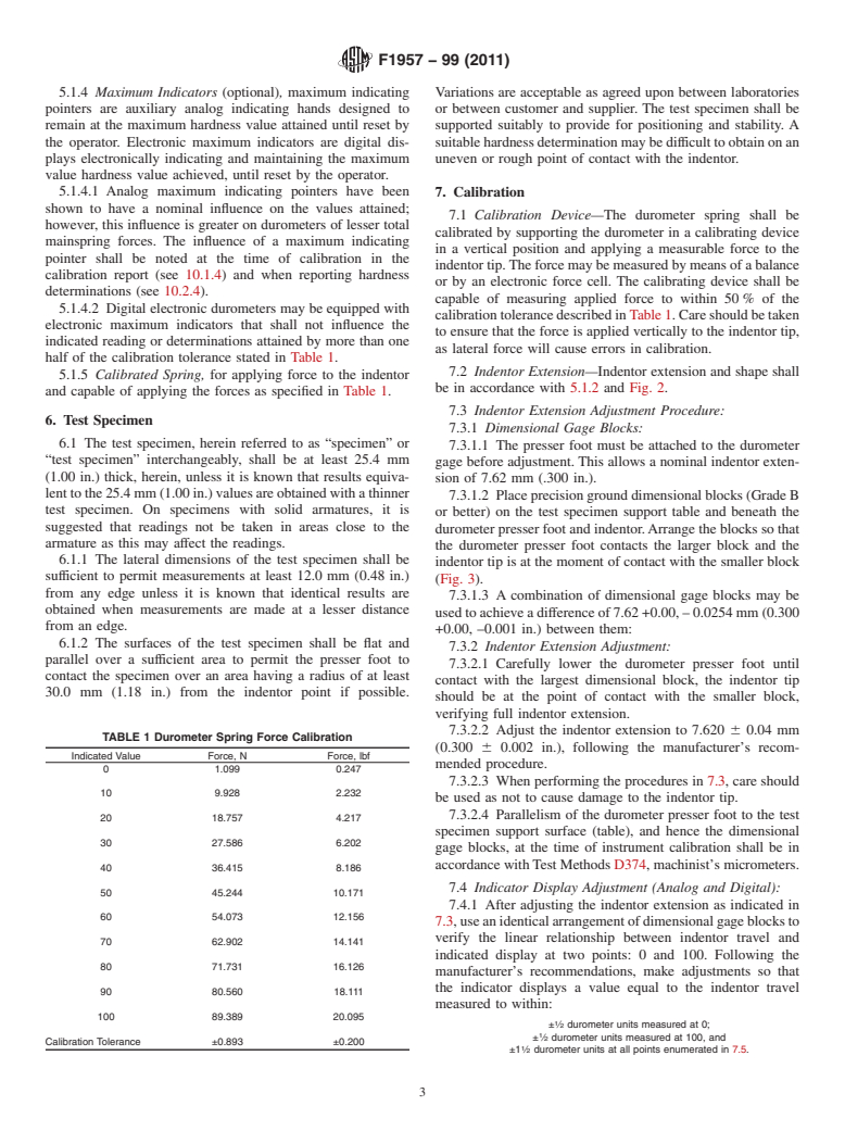
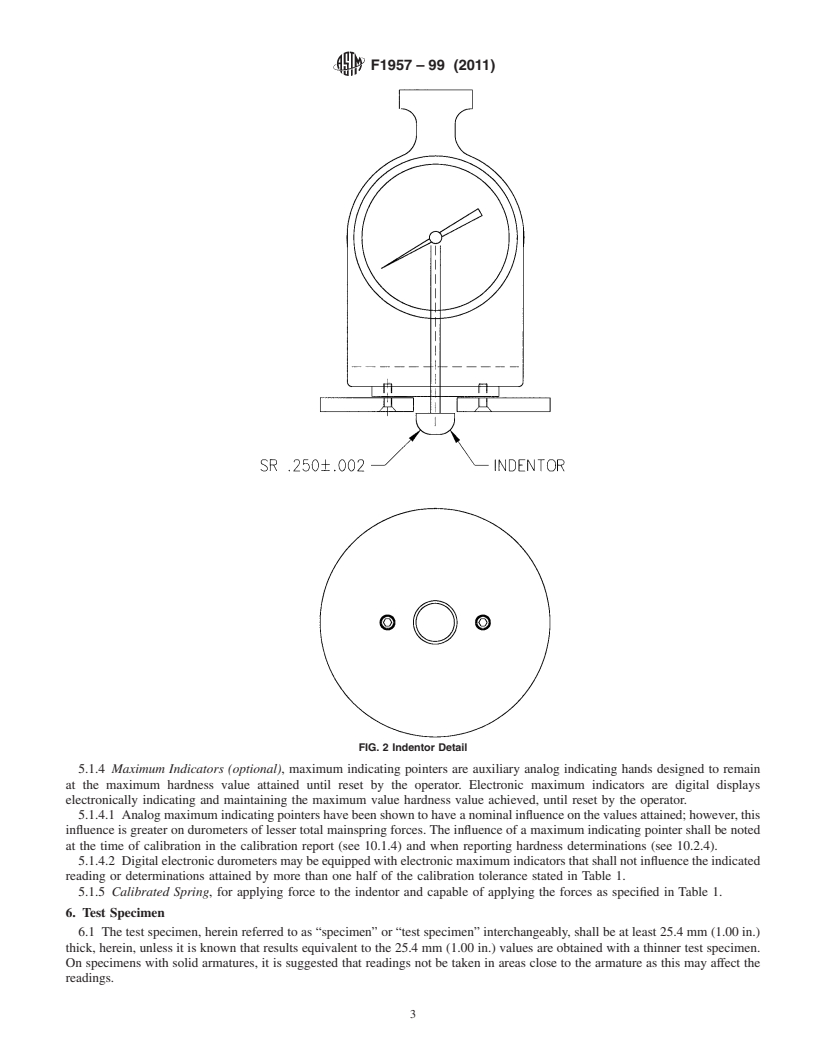
5.1.2 Indentor, formed from steel rod, shaped in accordance
with Fig. 2, polished over the contact area so that no flaws are
visibleunder20×magnificationandwithanindentorextension
of 7.62 6 0.04 mm (.300 6 0.002 in.).
FIG. 2 Indentor Detail
5.1.3 Indentor Extension Indicating Display, (analog or
digital electronic), having a display that is an inverse function
of the indentor extension.
5.1.3.1 Digital Electronic Indicating Displays shall indicate
from0to100,withnolessthan100equaldivisionsthroughout
the range, at a rate of one hardness point for each 0.50 mm
(0.002 in.) of indentor movement.
5.1.3.2 Analog Indicating Displays shall indicate from 0 to
100, with no less 100 equal divisions throughout the range or
alternatively with no less than 90 equal divisions throughout a
range from 10 to 100, at a rate of one hardness point for each
FIG. 1 Presser Foot Detail 0.050 mm (0.002 in.) of indentor movement.
F1957 − 99 (2011)
5.1.4 Maximum Indicators (optional), maximum indicating Variations are acceptable as agreed upon between laboratories
pointers are auxiliary analog indicating hands designed to or between customer and supplier. The test specimen shall be
remain at the maximum hardness value attained until reset by supported suitably to provide for positioning and stability. A
the operator. Electronic maximum indicators are digital dis- suitablehardnessdeterminationmaybedifficulttoobtainonan
plays electronically indicating and maintaining the maximum uneven or rough point of contact with the indentor.
value hardness value achieved, until reset by the operator.
5.1.4.1 Analog maximum indicating pointers have been
7. Calibration
shown to have a nominal influence on the values attained;
7.1 Calibration Device—The durometer spring shall be
however, this influence is greater on durometers of lesser total
calibrated by supporting the durometer in a calibrating device
mainspring forces. The influence of a maximum indicating
in a vertical position and applying a measurable force to the
pointer shall be noted at the time of calibration in the
indentortip.Theforcemaybemeasuredbymeansofabalance
calibration report (see 10.1.4) and when reporting hardness
or by an electronic force cell. The calibrating device shall be
determinations (see 10.2.4).
capable of measuring applied force to within 50% of the
5.1.4.2 Digital electronic durometers may be equipped with
calibrationtolerancedescribedinTable1.Careshouldbetaken
electronic maximum indicators that shall not influence the
to ensure that the force is applied vertically to the indentor tip,
indicated reading or determinations attained by more than one
as lateral force will cause errors in calibration.
half of the calibration tolerance stated in Table 1.
7.2 Indentor Extension—Indentor extension and shape shall
5.1.5 Calibrated Spring, for applying force to the indentor
be in accordance with 5.1.2 and Fig. 2.
and capable of applying the forces as specified in Table 1.
7.3 Indentor Extension Adjustment Procedure:
6. Test Specimen
7.3.1 Dimensional Gage Blocks:
6.1 The test specimen, herein referred to as “specimen” or
7.3.1.1 The presser foot must be attached to the durometer
“test specimen” interchangeably, shall be at least 25.4 mm
gage before adjustment.This allows a nominal indentor exten-
(1.00 in.) thick, herein, unless it is known that results equiva-
sion of 7.62 mm (.300 in.).
lenttothe25.4mm(1.00in.)valuesareobtainedwithathinner
7.3.1.2 Placeprecisiongrounddimensionalblocks(GradeB
test specimen. On specimens with solid armatures, it is
or better) on the test specimen support table and beneath the
suggested that readings not be taken in areas close to the
durometerpresserfootandindentor.Arrangetheblockssothat
armature as this may affect the readings.
the durometer presser foot contacts the larger block and the
6.1.1 The lateral dimensions of the test specimen shall be
indentor tip is at the moment of contact with the smaller block
sufficient to permit measurements at least 12.0 mm (0.48 in.)
(Fig. 3).
from any edge unless it is known that identical results are
7.3.1.3 A combination of dimensional gage blocks may be
obtained when measurements are made at a lesser distance
usedtoachieveadifferenceof7.62+0.00,–0.0254mm(0.300
from an edge.
+0.00, –0.001 in.) between them:
6.1.2 The surfaces of the test specimen shall be flat and
7.3.2 Indentor Extension Adjustment:
parallel over a sufficient area to permit the presser foot to
7.3.2.1 Carefully lower the durometer presser foot until
contact the specimen over an area having a radius of at least
contact with the largest dimensional block, the indentor tip
30.0 mm (1.18 in.) from the indentor point if possible.
should be at the point of contact with the smaller block,
verifying full indentor extension.
7.3.2.2 Adjust the indentor extension to 7.620 6 0.04 mm
TABLE 1 Durometer Spring Force Calibration
(0.300 6 0.002 in.), following the manufacturer’s recom-
Indicated Value Force, N Force, lbf
mended procedure.
0 1.099 0.247
7.3.2.3 When performing the procedures in 7.3, care should
10 9.928 2.232
be used as not to cause damage to the indentor tip.
7.3.2.4 Parallelism of the durometer presser foot to the test
20 18.757 4.217
specimen support surface (table), and hence the dimensional
30 27.586 6.202
gage blocks, at the time of instrument calibration shall be in
accordancewithTestMethodsD374,machinist’smicrometers.
40 36.415 8.186
7.4 Indicator Display Adjustment (Analog and Digital):
50 45.244 10.171
7.4.1 After adjusting the indentor extension as indicated in
60 54.073 12.156
7.3,useanidenticalarrangementofdimensionalgageblocksto
verify the linear relationship between indentor travel and
70 62.902 14.141
indicated display at two points: 0 and 100. Following the
80 71.731 16.126
manufacturer’s recommendations, make adjustments so that
the indicator displays a value equal to the indentor travel
90 80.560 18.111
measured to within:
100 89.389 20.095
± ⁄2 durometer units measured at 0;
± ⁄2 durometer units measured at 100, and
Calibration Tolerance ±0.893 ±0.200
±1 ⁄2 durometer units at all points enumerated in 7.5.
F1957 − 99 (2011)
7.6.2 Placethedurometerinthecalibrationdevice(see7.1).
Apply the forces indicated in Table 1 so that the forces applied
are aligned with the centerline of the indentor in a fashion that
eliminates shock or vibration and adjust the durometer in
accordance with the manufacturer’s recommendations.
7.7 The metal or rubber reference blocks provided for
checkingdurometeroperationandstateofcalibrationarenotto
be relied upon as calibration standards. The calibration proce-
dures outlined in Section 7 are the only valid calibration
procedures.
7.8 Spring force calibration tolerance is 61.0 durometer
unit. Spring force calibration tolerance is calculated as 1%.
7.9 Spring Force Combinations:
7.9.1 For Type CF Durometers:
force, N 51.098710.8829H (1)
CF
where:
H = one durometer unit on Type CF durometers.
CF
8. Instrument and Test Specimen Conditioning
8.1 Tests or instrument calibrations shall be conducted at
23.0 6 2.0° C (73.4 6 3.6° F).
8.2 The instrument and specimen(s) to be tested shall be
maintainedat23.0 62.0°C(73.4 63.6°F)foraminimumof
12 h prior to performing a test or calibration.
8.3 For materials whose hardness depends on relative
humidity,thetestspecimensshallbeconditionedinaccordance
with Procedure A of Practice D618 and tested under the same
conditions.
8.3.1 Accordingly, the relative humidity at the time of a test
shall be reported in 10.2.2.
8.3.2 The relative humidity may be reported in 10.2.2 when
the influence of relative humidity on the hardness of the test
specimen is not known.
8.3.3 The relative humidity at the time of instrument cali-
bration shall be reported in 10.1.6.
8.4 No conclusive evaluation has been made on durometers
at temperatures other than 23.0 6 2.0 °C (73.4 6 3.6 °F).
Conditioning at temperatures other than the above may show
FIG. 3 Indentor Extension Calibration Setup
changes in calibration. Durometer use at temperatures other
than the above should be decided between customer and
supplier (see Practice D1349).
7.4.2 Each durometer point indicated is equal to 0.050 mm
8.5 These procedures may be modified if agreed upon
(0.002 in.) of indentor travel.
between laboratories or between customer and supplier.
7.5 Spring Calibration—The durometer spring shall be
calibrated at displayed readings 20, 30, 40, 50, 60, 70, 80, and
9. Procedure
90. The measured force (9.8 × mass in kilograms) shall be
within the calibration tolerance specified in Table 1, which
9.1 Manual (Hand-Held) Durometer Testing:
identifies the measured force applied to the indentor for the
9.1.1 Care shall be exercised to minimize the exposure of
entire range of the instrument, although it is necessary only to
the instrument to environmental conditions that are adverse to
verify the spring calibration at points listed herein.
the performance of the instrument or adversely influence test
results.
7.6 Spring Calibration Procedure:
7.6.1 Assure that the indentor extension has been adjusted 9.1.2 Place the test specimen on a flat, hard, horizontal
in accordance with 7.3 and the linear relationship between surface. Hold the durometer in a vertical position with the
indentor travel and indicated display is as specified in 7.4. indentortipatadistancefromanyedgeofthetestspecimenas
F1957 − 99 (2011)
described in Section 6, unless i
...
This document is not anASTM standard and is intended only to provide the user of anASTM standard an indication of what changes have been made to the previous version. Because
it may not be technically possible to adequately depict all changes accurately, ASTM recommends that users consult prior editions as appropriate. In all cases only the current version
of the standard as published by ASTM is to be considered the official document.
Designation:F1957–99(Reapproved 2004) Designation:F1957–99(Reapproved 2011)
Standard Test Method for
Composite Foam Hardness-Durometer Hardness
This standard is issued under the fixed designation F1957; the number immediately following the designation indicates the year of
original adoption or, in the case of revision, the year of last revision. A number in parentheses indicates the year of last reapproval. A
superscript epsilon (´) indicates an editorial change since the last revision or reapproval.
1. Scope
1.1 This test method describes a type of composite foam hardness measurement device known as durometer: Type CF. The
procedure for determining indentation hardness of substances comprised of two or more elastomeric materials, one of which is a
foam or foam like material. These are classified as composite foam structures. The composite foam product may have an armature
made of a material suitable for adding structural integrity including but not limited to metal, plastic, or wood. This construction
is typical for lapbar restraints, seating, and other restraint devices, as well as some show elements.
1.2 This test method is not equivalent to other indentation hardness methods and instrument types, specifically those described
in Test Methods D1415 and D2240.
1.3 The values stated in SI units are to be regarded as standard. The values given in parentheses are for information only. Many
of the stated dimensions in SI are direct conversions from the U.S. customary system to accommodate the instrumentation,
practices, and procedures that existed prior to the Metric Conversion Act of 1975.
1.4 All materials, instruments, or equipment used for the determination of mass or dimension shall have traceability to the
National Institute for Standards and Technology (NIST) or other internationally recognized organizations.
1.5 This test method is not a safety standard as it pertains to ride legislation. The use of this test method is optional based upon
an agreement between customers and suppliers of foam products.
1.6 This standard does not purport to address all of the safety concerns, if any, associated with its use. It is the responsibility
of the user of this standard to establish appropriate safety and health practices and determine the applicability of regulatory
limitations prior to use.
2. Referenced Documents
2.1 ASTM Standards:
D374 Test Methods for Thickness of Solid Electrical Insulation
D618 Practice for Conditioning Plastics for Testing
D785 Test Method for Rockwell Hardness of Plastics and Electrical Insulating Materials
D1349 Practice for RubberStandard Temperatures for Testing
D1415 Test Method for Rubber PropertyInternational Hardness
D2240 Test Method for Rubber PropertyDurometer Hardness
D4483 Practice for Evaluating Precision for Test Method Standards in the Rubber and Carbon Black Manufacturing Industries
3. Summary of Test Method
3.1 This test method permits hardness measurements based on either initial indentation or indentation after a specified period
of time, or both.
3.2 Those specimens, which have a durometer hardness range other than specified, shall use another suitable procedure for
determining durometer hardness.
4. Significance and Use
4.1 This test method is based on the penetration by a specific type of indentor when forced into the material under specified
conditions.Theindentationhardnessisrelatedinverselytothepenetrationandisdependentontheelasticmodulusandviscoelastic
behavior of the material. The geometry of the indentor and the applied force influence the measurements, such that no simple
This test method is under the jurisdiction of ASTM Committee F24 on Amusement Rides and Devices and is the direct responsibility of F24.10 on Test Methods.
Current edition approved Oct. 1, 2004. Published October 2004. Originally approved in 1999. Last previous edition approved in 1999 as F1957–99. DOI:
10.1520/F1957-99R04.
Current edition approved Jan. 15, 2011. Published June 2011. Originally approved in 1999. Last previous edition approved in 2004 as F1957 – 99 (2004). DOI:
10.1520/F1957-99R11.
For referencedASTM standards, visit theASTM website, www.astm.org, or contactASTM Customer Service at service@astm.org. For Annual Book ofASTM Standards
volume information, refer to the standard’s Document Summary page on the ASTM website.
Copyright © ASTM International, 100 Barr Harbor Drive, PO Box C700, West Conshohocken, PA 19428-2959, United States.
F1957–99 (2011)
relationship exists between the measurements obtained with one type of durometer and those obtained with another type of
durometer or other instruments used for measuring hardness. This test method is an empirical test intended primarily for control
purposes.Nosimplerelationshipexistsbetweenindentationhardnessdeterminedbythistestmethodandanyfundamentalproperty
of the material tested. For specification purposes it is recommended that Test Method D785 be used for hard materials and Test
Method D2240 be used for solid elatomers.
5. Apparatus
5.1 Hardness measurement apparatus, or durometer, consisting of the following components:
5.1.1 Presser Foot, with an orifice (to allow for the protrusion of the indentor) having a diameter as specified in Fig. 1 with the
center a minimum of 38.0 mm (1.5 in.) from any edge of the flat circular presser foot.
5.1.2 Indentor, formed from steel rod, shaped in accordance with Fig. 2, polished over the contact area so that no flaws are
visible under 203 magnification and with an indentor extension of 7.62 6 0.04 mm (.300 6 0.002 in.).
5.1.3 Indentor Extension Indicating Display, (analog or digital electronic), having a display that is an inverse function of the
indentor extension.
5.1.3.1 Digital Electronic Indicating Displays shall indicate from 0 to 100, with no less than 100 equal divisions throughout
the range, at a rate of one hardness point for each 0.50 mm (0.002 in.) of indentor movement.
5.1.3.2 Analog Indicating Displays shall indicate from 0 to 100, with no less 100 equal divisions throughout the range or
alternatively with no less than 90 equal divisions throughout a range from 10 to 100, at a rate of one hardness point for each 0.050
mm (0.002 in.) of indentor movement.
FIG. 1 Presser Foot Detail
F1957–99 (2011)
FIG. 2 Indentor Detail
5.1.4 Maximum Indicators (optional), maximum indicating pointers are auxiliary analog indicating hands designed to remain
at the maximum hardness value attained until reset by the operator. Electronic maximum indicators are digital displays
electronically indicating and maintaining the maximum value hardness value achieved, until reset by the operator.
5.1.4.1 Analogmaximumindicatingpointershavebeenshowntohaveanominalinfluenceonthevaluesattained;however,this
influence is greater on durometers of lesser total mainspring forces. The influence of a maximum indicating pointer shall be noted
at the time of calibration in the calibration report (see 10.1.4) and when reporting hardness determinations (see 10.2.4).
5.1.4.2 Digitalelectronicdurometersmaybeequippedwithelectronicmaximumindicatorsthatshallnotinfluencetheindicated
reading or determinations attained by more than one half of the calibration tolerance stated in Table 1.
5.1.5 Calibrated Spring, for applying force to the indentor and capable of applying the forces as specified in Table 1.
6. Test Specimen
6.1 The test specimen, herein referred to as “specimen” or “test specimen” interchangeably, shall be at least 25.4 mm (1.00 in.)
thick, herein, unless it is known that results equivalent to the 25.4 mm (1.00 in.) values are obtained with a thinner test specimen.
On specimens with solid armatures, it is suggested that readings not be taken in areas close to the armature as this may affect the
readings.
F1957–99 (2011)
TABLE 1 Durometer Spring Force Calibration
Indicated Value Force, N Force, lbf
0 1.099 0.247
10 9.928 2.232
20 18.757 4.217
30 27.586 6.202
40 36.415 8.186
50 45.244 10.171
60 54.073 12.156
70 62.902 14.141
80 71.731 16.126
90 80.560 18.111
100 89.389 20.095
Calibration Tolerance 60.893 60.200
6.1.1 The lateral dimensions of the test specimen shall be sufficient to permit measurements at least 12.0 mm (0.48 in.) from
any edge unless it is known that identical results are obtained when measurements are made at a lesser distance from an edge.
6.1.2 The surfaces of the test specimen shall be flat and parallel over a sufficient area to permit the presser foot to contact the
specimen over an area having a radius of at least 30.0 mm (1.18 in.) from the indentor point if possible. Variations are acceptable
as agreed upon between laboratories or between customer and supplier. The test specimen shall be supported suitably to provide
for positioning and stability. A suitable hardness determination may be difficult to obtain on an uneven or rough point of contact
with the indentor.
7. Calibration
7.1 Calibration Device—The durometer spring shall be calibrated by supporting the durometer in a calibrating device in a
vertical position and applying a measurable force to the indentor tip. The force may be measured by means of a balance or by an
electronic force cell.The calibrating device shall be capable of measuring applied force to within 50 % of the calibration tolerance
describedinTable1.Careshouldbetakentoensurethattheforceisappliedverticallytotheindentortip,aslateralforcewillcause
errors in calibration.
7.2 Indentor Extension—Indentor extension and shape shall be in accordance with 5.1.2 and Fig. 2.
7.3 Indentor Extension Adjustment Procedure:
7.3.1 Dimensional Gage Blocks:
7.3.1.1 The presser foot must be attached to the durometer gage before adjustment. This allows a nominal indentor extension
of 7.62 mm (.300 in.).
7.3.1.2 Place precision ground dimensional blocks (Grade B or better) on the test specimen support table and beneath the
durometerpresserfootandindentor.Arrangetheblockssothatthedurometerpresserfootcontactsthelargerblockandtheindentor
tip is at the moment of contact with the smaller block (Fig. 3).
7.3.1.3 A combination of dimensional gage blocks may be used to achieve a difference of 7.62 +0.00, – 0.0254 mm (0.300
+0.00, –0.001 in.) between them:
7.3.2 Indentor Extension Adjustment:
7.3.2.1 Carefully lower the durometer presser foot until contact with the largest dimensional block, the indentor tip should be
at the point of contact with the smaller block, verifying full indentor extension.
7.3.2.2 Adjust the indentor extension to 7.620 6 0.04 mm (0.300 6 0.002 in.), following the manufacturer’s recommended
procedure.
7.3.2.3 When performing the procedures in 7.3, care should be used as not to cause damage to the indentor tip.
7.3.2.4 Parallelism of the durometer presser foot to the test specimen support surface (table), and hence the dimensional gage
blocks, at the time of instrument calibration shall be in accordance with Test Methods D374, machinist’s micrometers.
7.4 Indicator Display Adjustment (Analog and Digital):
7.4.1 After adjusting the indentor extension as indicated in 7.3, use an identical arrangement of dimensional gage blocks to
verify the linear relationship between indentor travel and indicated display at two points: 0 and 100. Following the manufacturer’s
recommendations, make adjustments so that the indicator displays a value equal to the indentor travel measured to within:
F1957–99 (2011)
FIG. 3 Indentor Extension Calibration Setup
6 ⁄2 durometer units measured at 0;
6 ⁄2 durometer units measured at 100, and
61 ⁄2 durometer units at all points enumerated in 7.5.
7.4.2 Each durometer point indicated is equal to 0.050 mm (0.002 in.) of indentor travel.
7.5 Spring Calibration—The durometer spring shall be calibrated at displayed readings 20, 30, 40, 50, 60, 70, 80, and 90. The
measured force (9.8 3 mass in kilograms) shall be within the calibration tolerance specified in Table 1, which identifies the
measured force applied to the indentor for the entire range of the instrument, although it is necessary only to verify the spring
calibration at points listed herein.
7.6 Spring Calibration Procedure:
7.6.1 Assure that the indentor extension has been adjusted in accordance with 7.3 and the linear relationship between indentor
travel and indicated display is as specified in 7.4.
7.6.2 Place the durometer in the calibration device (see 7.1).Apply the forces indicated in Table 1 so that the forces applied are
aligned with the centerline of the indentor in a fashion that eliminates shock or vibration and adjust the durometer in accordance
with the manufacturer’s recommendations.
7.7 The metal or rubber reference blocks provided for checking durometer operation and state of calibration are not to be relied
F1957–99 (2011)
upon as calibration standards. The calibration procedures outlined in Section 7 are the only valid calibration procedures.
7.8 Spring force calibration tolerance is 61.0 durometer unit. Spring force calibration tolerance is calculated as 1 %.
7.9 Spring Force Combinations:
7.9.1 For Type CF Durometers:
force, N 5 1.0987 1 0.8829 H (1)
CF
where:
H = one durometer unit on Type CF durometers.
CF
8. Instrument and Test Specimen Conditioning
8.1 Tests or instrument calibrations shall be conducted at 23.0 6 2.0° C (73.4 6 3.6° F).
8.2 The instrument and specimen(s) to be tested shall be maintained at 23.0 6 2.0° C (73.4 6 3.6° F) for a minimum of 12
h prior to performing a test or calibration.
8.3 For materials whose hardness depends on relative humidity, the test specimens shall be conditioned in accordance with
Procedure A of Practice D618 and tested under the same conditions.
8.3.1 Accordingly, the relative humidity at the time of a test shall be reported in 10.2.2.
8.3.2 The relative humidity may be reported in 10.2.2 when the influence of relative humidity on the hardness of the test
specimen is not known.
8.3.3 The relative humidity at the time of instrument calibration shall be reported in 10.1.6.
8.4 No conclusive evaluation has been made on durometers at temperatures other than 23.0 6 2.0 °C (73.4 6 3.6 °F).
Conditioning at temperatures other than the above may show changes in calibration. Durometer use at temperatures other than the
above should be decided between customer and supplier (see Practice D1349).
8.5 These procedures may be modified if agree
...
Questions, Comments and Discussion
Ask us and Technical Secretary will try to provide an answer. You can facilitate discussion about the standard in here.