


ASTM D2758-94(2003)
(Test Method)Standard Test Method for Engine Coolants by Engine Dynamometer
Standard Test Method for Engine Coolants by Engine Dynamometer
SIGNIFICANCE AND USE
This test method provides a laboratory technique capable of reproducing the complex environmental stresses a coolant encounters under actual engine operating conditions. The test method provides improved discrimination over glassware and simulated service tests and improved correlation with field service. Although the test method is particularly valuable for developing coolants for increased service requirements, it remains that field testing is necessary to evaluate coolant performance completely.
SCOPE
1.1 This test method covers a full-scale clean engine test designed to evaluate corrosion protection and inhibitor stability of engine coolants under simulated heavy-duty driving conditions.
1.2 The values stated in SI units are to be regarded as the standard. The values given in parentheses are for information only.
1.3 This standard does not purport to address all of the safety concerns, if any, associated with its use. It is the responsibility of the user of this standard to establish appropriate safety and health practices and determine the applicability of regulatory limitations prior to use. Specific hazards statements are given in Section 6.
General Information
Relations

Standards Content (Sample)
NOTICE: This standard has either been superseded and replaced by a new version or withdrawn.
Contact ASTM International (www.astm.org) for the latest information
Designation:D2758–94 (Reapproved 2003)
Standard Test Method for
Engine Coolants by Engine Dynamometer
This standard is issued under the fixed designation D2758; the number immediately following the designation indicates the year of
original adoption or, in the case of revision, the year of last revision. A number in parentheses indicates the year of last reapproval. A
superscript epsilon (´) indicates an editorial change since the last revision or reapproval.
1. Scope tion of (1) coolant samples, (2) metal corrosion specimens, and
( 3) cooling system components.
1.1 This test method covers a full-scale clean engine test
designedtoevaluatecorrosionprotectionandinhibitorstability
4. Significance and Use
of engine coolants under simulated heavy-duty driving condi-
4.1 This test method provides a laboratory technique ca-
tions.
pable of reproducing the complex environmental stresses a
1.2 The values stated in SI units are to be regarded as the
coolant encounters under actual engine operating conditions.
standard. The values given in parentheses are for information
The test method provides improved discrimination over glass-
only.
ware and simulated service tests and improved correlation with
1.3 This standard does not purport to address all of the
field service. Although the test method is particularly valuable
safety concerns, if any, associated with its use. It is the
for developing coolants for increased service requirements, it
responsibility of the user of this standard to establish appro-
remains that field testing is necessary to evaluate coolant
priate safety and health practices and determine the applica-
performance completely.
bility of regulatory limitations prior to use. Specific hazards
statements are given in Section 6.
5. Apparatus
5.1 Test Engine— The test engine shall be a volume
2. Referenced Documents
production passenger car engine of cast iron or aluminum
2.1 ASTM Standards:
construction. Engine speed and brake horsepower should be
D1121 Test Method for ReserveAlkalinity of Engine Cool-
calculated and adjusted to be equivalent to a 96.5 km/h (60
ants and Antirusts
mph) level road load. Aluminum accessories, such as coolant
D1287 Test Method for pH of Engine Coolants and Anti-
pump and timing chain cover, are optional.The engine shall be
rusts
equipped with a matching radiator and pressure cap.Acoolant
D1384 Test Method for Corrosion Test for Engine Coolants
3 overflow reservoir and closed-system pressure cap are op-
in Glassware
tional, except when specified by the manufacturer. Assemble
G1 Practice for Preparing, Cleaning, and Evaluating Corro-
the test components to provide a complete cooling system.The
sion Test Specimens
4 relativepositioningoftheradiatorandengineshouldduplicate,
2.2 Federal Standard:
as closely as practicable, the mounting in the automobile with
CFR Title 29 OSHA Regulations
the fan omitted. All radiator hose lengths should be held to a
3. Summary of Test Method minimum. The radiator shall be cooled by forced air.
5.2 Instrumentation and Control (See Fig. 1)—Run the
3.1 This test method involves the operation of a standard
engine on a test stand coupled to an engine dynamometer with
passenger car engine on a dynamometer stand under constant
appropriate accessories for control of the designated operating
speed, load, and coolant temperature conditions for a total of
conditions. Measure engine coolant temperature out of the
700 h. The performance of the coolant is judged by examina-
engine at a point immediately adjacent to the coolant outlet.
Measure manifold vacuum, oil pressure, and exhaust pressure
This test method is under the jurisdiction ofASTM Committee D15 on Engine
at appropriate points and monitor them throughout the test in
Coolants and is the direct responsibility of Subcommittee D15.10 on Dynamometer
order to ensure proper engine performance. Install a pressure
and Road Tests.
gage in the outlet tank of a crossflow radiator or the top tank of
Current edition approved Dec. 15, 1994. Published February 1995. Originally
a downflow radiator to read the gage pressure.
published as D2758 – 68 T. Last previous edition D2758 – 86 (1991)´ . DOI:
10.1520/D2758-94R03.
5.3 Corrosion Measurements:
Annual Book of ASTM Standards, Vol 15.05.
5.3.1 Evaluate corrosion protection using metal specimens.
Annual Book of ASTM Standards, Vol 03.02.
4 The specimen arrangement shall be basically that used in Test
Available from the Occupational Safety and Health Administration, 200
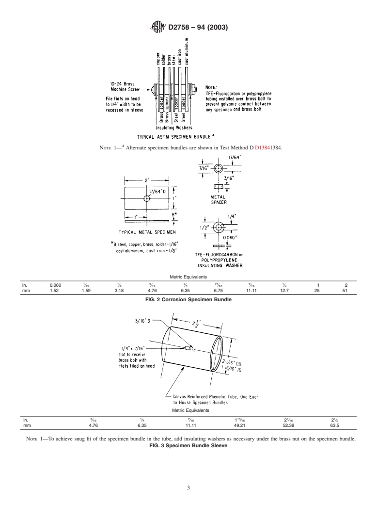
Constitution Ave., N.W., Washington, DC 20008. Method D1384. The specimen bundle is shown in Fig. 2.
Copyright © ASTM International, 100 Barr Harbor Drive, PO Box C700, West Conshohocken, PA 19428-2959, United States.
D2758–94 (2003)
FIG. 1 Air Cooling Setup
Preparation, cleaning, and weighing of the metal specimens are position. Connect the bottom fitting of the capsule with a
described in Test Method D1384 and Practice G1. Each rubber hose to the standard heater supply nipple, and connect
specimen bundle shall be held in a canvas-reinforced phenolic
the top fitting to the return nipple on the coolant pump.
tube (see Fig. 3) which, in turn, is contained in a capsule. Use
5.4 Fuel and Crankcase Oil—Because of the extended
two types of specimen capsules: full-flow and bypass. Install
duration of this test, it is suggested that high-quality fuels and
thefull-flowcapsuleintheupperradiatorhose,andconnectthe
motor oils be selected to control combustion problems and
bypass capsule across the heater taps of the engine. Details of
achieve maximum valve life.
the capsules are shown in Fig. 4 and Fig. 5. The full-flow
capsule shall contain three sets of specimens; weigh and
6. Precautions
replace one set with a fresh set at 100-h increments, and weigh
two sets at the conclusion of the test. The bypass capsule shall 6.1 Safety Precautions:
contain three sets of specimens; clean, weigh, and replace the
6.1.1 Coolant—All coolant concentrates and their solutions
first set at 100-h increments. Clean and weigh the second set at
should be considered harmful or fatal if swallowed.
400 h. Replace, clean, and weigh this set at the end of the test.
6.1.2 Specimen Cleaning—When cleaning aluminum speci-
Clean and weigh the third set at the end of the test.
mens with chromic acid/orthophosphoric acid solution, use
5.3.2 Position the full-flow capsule in the upper radiator
fume hood.
hose at a point below the radiator coolant level.
6.1.3 PersonalProtection—Appropriatepersonalprotection
5.3.3 The bypass capsule should be located in close prox-
equipment (safety glasses, gloves, etc.) should be worn at all
imity to the engine in order to avoid excessive coolant
times when working with hot, pressurized engine systems. In
temperature drop.
general, engine speed should be lowered to 1000 rpm at no
5.3.4 Equip the bypass capsule with a temperature-
load, and the temperature and pressure on the cooling system
measuring device to assure that normal flow is being main-
should be lowered to a level below the boiling point of the
tained.(Atemperaturedropfromnormaloperatingtemperature
coolant before approaching the engine. To avoid possible
indicates an obstruction in the bypass circuit.) A mounting
burns, care should be exercised in venting and opening the
bracket attached to the radiator stand is recommended. Mount
the capsule below the radiator coolant level in a vertical radiator pressure cap.
D2758–94 (2003)
A
NOTE 1— Alternate specimen bundles are shown in Test Method D D13841384.
Metric Equivalents
1 1 3 1 17 7 1
in. 0.060 ⁄16 ⁄8 ⁄16 ⁄4 ⁄64 ⁄16 ⁄2 12
mm 1.52 1.59 3.18 4.76 6.35 6.75 11.11 12.7 25 51
FIG. 2 Corrosion Specimen Bundle
Metric Equivalents
3 1 7 15 1 1
in. ⁄16 ⁄4 ⁄16 1 ⁄16 2 ⁄16 2 ⁄2
mm 4.76 6.35 11.11 49.21 52.39 63.5
NOTE 1—To achieve snug fit of the specimen bundle in the tube, add insulating washers as necessary under the brass nut on the specimen bundle.
FIG. 3 Specimen Bundle Sleeve
D2758–94 (2003)
Metric Equivalents
Metric Equivalents
1 1
in. 1 ⁄2 22 ⁄4
mm 38 50.8 57 3 1
in ⁄8 2 ⁄4
mm 9.5 57
FIG. 4 Upper Radiator Hose Full Flow Specimen Capsule
FIG. 5 By-Pass Specimen Capsule
6.1.4 Safety Guards— Sturdy safety guards must be used
for the fan belt, pulleys, couplings, and drive shaft (see OSHA
gas leakage at some advanced point in the test, possibly
Regulations, CFR Title 29).
voiding the test and its results. A new radiator should be
6.1.5 MaintenanceofPhysicalEquipment—Intheoperation
installed before each test. The cooling system should be
and planning of the dynamometer test facility, adequate fore-
checked for the following common defects: (1) cylinder head
thought must be given to the fuel system, exhaust system, fire
gasket leakage resulting in exhaust gas contamination of the
hazards, and general housekeeping in order to maintain a high
coolant, (2) air induction into the coolant due to a worn coolant
level of safety standards. For example, checks for leaks in the
pump seal, and (3) defective lower radiator hose connection.
fuel, oil, and exhaust systems must be made on a continuing
Methods of checking for these defects appear in Annex A1.
basis, and consideration must be given to the routing of a hot
7.1.2 Clean the engine cooling system with a chelator-type
exhaust system in an area of combustible materials.
commerical cleaner (seeAnnexA2). Replace all hoses after the
cleaning procedure, but before each test.
7. Preparation of Apparatus
7.2 Installation of Test Specimens and Coolant:
7.2.1 Prior to the installation of the coolant, install a new
7.1 Engine Reconditioning:
7.1.1 Check the engine and recondition, if necessary, prior aluminum coolant outlet (if the engine is so equipped), along
withathermostatfixedinthefullopenposition(seeNote).Flat
to each test run. For each new engine, prior to a series of tests,
and those engines being reconditioned for further testing, washers should be used under the coolant outlet-attaching bolt
heads to minimize damage to the mounting flanges. Install the
install new cylinder head gaskets; the engine manufacturer’s
recommendations should be followed regarding the use of specimen-containing capsules at this time.
gasket sealing compounds. When no specific recommendation
NOTE 1—Thermostats of different manufacturers have different design
is made by the engine manufacturer, the cylinder head gaskets
minimum travel positions. “Full open” would mean the maximum travel.
and other coolant sealing gaskets should be coated with an
To block a thermostat open, the power element should be drilled and
adhesive sealant. This will ensure against coolant and exhaust tapped for an adjusting screw, soldered into position and cut off. Never
D2758–94 (2003)
solder the piston to the piston guide as this may cause damage or
Coolant 40 volume % concentration of test coolant
annealing of other thermostat components.To determine maximum travel, in 100-100-100 corrosive water
Coolant outlet temperature 93 6 2°C (200 6 3°F) or optional
measure valve position equivalent to 11°C (20°F) above stamped opening
Exhaust pressure 0 to 25.4 mm (0 to 1 in.) Hg
temperature; for example, 89°C 1 11°C 5 100°C ~192°F 1
Test duration 700 h
20°F 5 212°F!.
Thermostat Fixed to remain full open
Radiator cap Standard specification for the engine cool-
7.2.2 Based upon careful measurement of the volume of the
ing system
Coolant level 19 mm ( ⁄4 in.) below pressure cap seat for
system, add a measured amount of concentrated coolant
down-flow radiators
directly to the cooling system to provide a 40 volume %
38 mm (1 ⁄2 in.) below pressure cap seat for
coolant solution when filled to overflow with water containing cross-flow radiators
At pressure cap seat when radiator is equip-
100 ppm each of chloride, sulfate, and bicarbonate ions (see
ped with an overflow reservoir and clos-
Annex A3). If desired, single-phase-inhibited coolant may be
ed-system pressure cap
Speed and brake hP Equivalent to 96.5 km/h (60 mph) level
premixed with corrosive water in a clean container and added
road load
to the cooling system as a solution. Under no conditions
premix external to the cooling system at the initiation of the 8.2 Perform periodic inspections throughout the test, as
test two-phase coolants containing polar oils. Before starting given in Table 1.
the test and after installing test coolant, conduct a 103-kPa
9. Interpretation and Significance of Results
(15-psi) pressure leakage test to check for external coolant
leakage at hoses, gaskets, and coolant pump.
9.1 The test method is intended to provide a more compre-
7.2.3 Withtheenginerunningat1000rpmnoloadand93°C hensive evaluation of coolant performance than is obtainable
with glassware and stimulated service tests. Correlation with
(200°F) coolant outlet temperature, drain sufficient coolant to
fieldserviceisgenerallygoodforenginesofsimilardesignand
bring the radiator level from overflow to 19 mm ( ⁄4 in.) below
1 material, but depends to a significant degree on the investiga-
the pressure cap seat for down-flow radiators, and 38 mm (1 ⁄2
tor’s ability to interpret test results in relation to field service
in.) below the pressure cap seat for cross-flow radiators. (When
experience. Field service will inherently impose variations in
radiator is equipped with an overflow reservoir and closed-
severity.
systempressurecap,coolantlevelshouldbeatthepressurecap
9.2 Theindividualspecimenweightlossvalueshavelimited
seat.) Replace radiator cap. Save the drained coolant, and add
significance in terms of absolute corrosion protection with
it to 2-L (2-qt) sample of premixed 40 % test coolant and
respect to field service. Instead, they must be compared to
corrosive water solution to use as makeup throughout the test.
baseline values established with coolants of known field
service performance. The comparative weight loss values
8. Procedure
encountered with those specimens that remain undisturbed for
8.1 Maintain the following test conditions throughout the
the duration of the test indicate overall corrosion protection by
test method, except for the inspections detailed in subsequent the test coolant. These specimens should be the most valuable
sections: to predict field service performance. The specimens, which are
TABLE 1 Periodic Inspections
Occurrence Operational Sequence
1 h, 100 h, and every 100 Reduce the engine speed to 1000 rpm no load and 93°C (200°F) coolant temperature. Withdraw
h thereafter 60-mL (2-oz) coolant sample. Samples should be analyzed in accordance with Test Methods D1287
and D1121D1287D1121.
Each 24-h operating Reduce the engine speed to 1000 rpm no load and 93°C (200°F) coolant temperature. R
...
Questions, Comments and Discussion
Ask us and Technical Secretary will try to provide an answer. You can facilitate discussion about the standard in here.