


ASTM F879-15(2020)
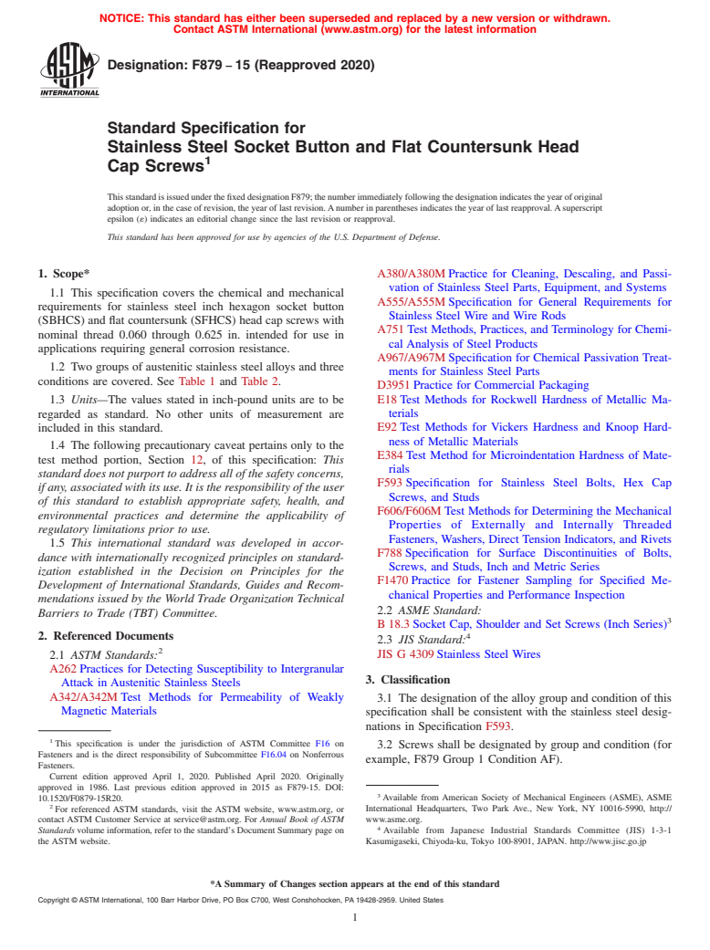
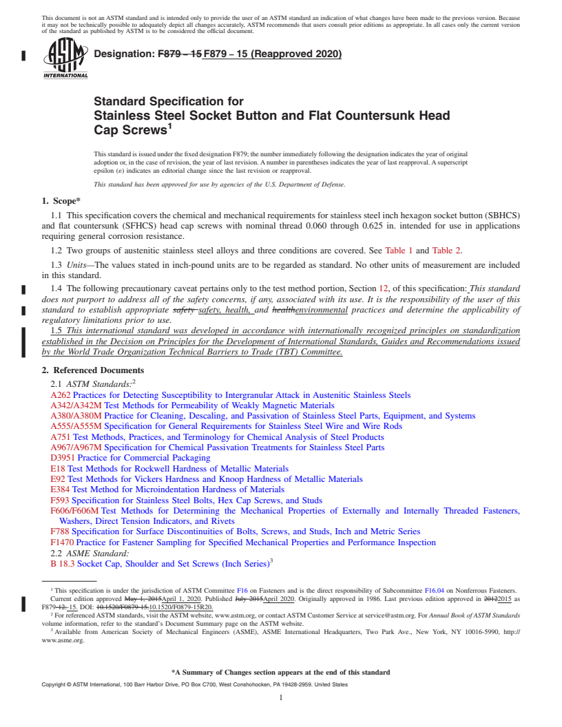
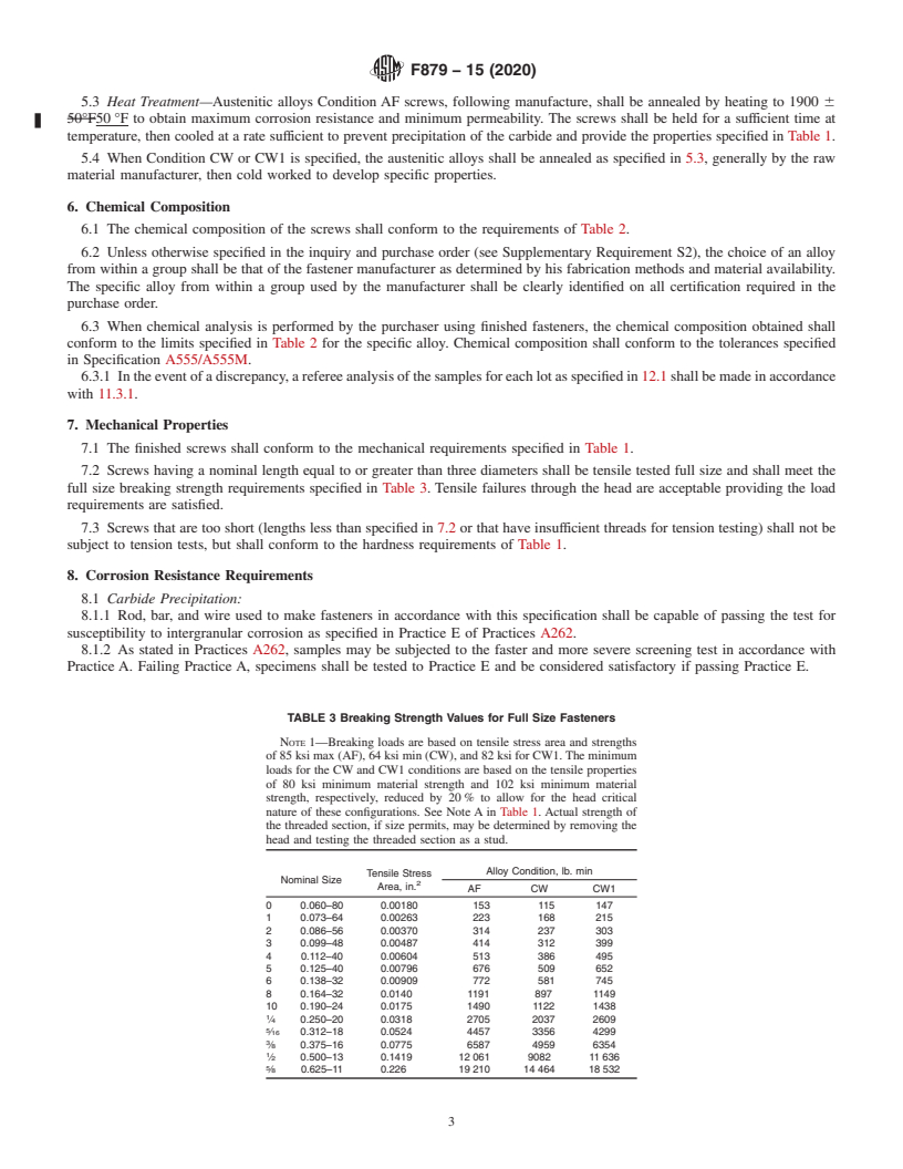
(Specification)Standard Specification for Stainless Steel Socket Button and Flat Countersunk Head Cap Screws
Standard Specification for Stainless Steel Socket Button and Flat Countersunk Head Cap Screws
ABSTRACT
This specification covers the chemical and mechanical requirements for stainless steel metric hexagon socket button (SBHCS) and flat countersunk (SFHCS) head cap screws with nominal thread M 3 through M 20 intended for use in applications requiring general corrosion resistance. These steels are designated into three classes: Austenitic Class A 1-50 in an annealed condition, Austenitic Class A1-55 in a cold worked condition, and Austenitic Class A 1-70 in a cold worked condition. The austenitic stainless steel socket screw shall be designated F879M A1-50, F879M A1–55, or F 879M A1-70. Screws shall be formed by upsetting or extruding, or both. Also, these screws shall be roll threaded. Austenitic alloys ClassA 1-50 screws, following manufacture, shall be annealed by heating to a certain temperature to obtain maximum corrosion resistance and minimum permeability. The screws shall be held for a sufficient time at temperature, then cooled at a rate sufficient to prevent precipitation of the carbide and provide the properties specified. Different tests shall be conducted in order to determine the following mechanical properties of screws: tensile strength, minimum extension, yield strength, elongation, Vickers hardness, and Rockwell hardness.
SCOPE
1.1 This specification covers the chemical and mechanical requirements for stainless steel inch hexagon socket button (SBHCS) and flat countersunk (SFHCS) head cap screws with nominal thread 0.060 through 0.625 in. intended for use in applications requiring general corrosion resistance.
1.2 Two groups of austenitic stainless steel alloys and three conditions are covered. See Table 1 and Table 2.
1.3 Units—The values stated in inch-pound units are to be regarded as standard. No other units of measurement are included in this standard.
1.4 The following precautionary caveat pertains only to the test method portion, Section 12, of this specification: This standard does not purport to address all of the safety concerns, if any, associated with its use. It is the responsibility of the user of this standard to establish appropriate safety, health, and environmental practices and determine the applicability of regulatory limitations prior to use.
1.5 This international standard was developed in accordance with internationally recognized principles on standardization established in the Decision on Principles for the Development of International Standards, Guides and Recommendations issued by the World Trade Organization Technical Barriers to Trade (TBT) Committee.
General Information
Buy Standard
Standards Content (Sample)
NOTICE: This standard has either been superseded and replaced by a new version or withdrawn.
Contact ASTM International (www.astm.org) for the latest information
Designation: F879 − 15 (Reapproved 2020)
Standard Specification for
Stainless Steel Socket Button and Flat Countersunk Head
Cap Screws
This standard is issued under the fixed designation F879; the number immediately following the designation indicates the year of original
adoption or, in the case of revision, the year of last revision. A number in parentheses indicates the year of last reapproval. A superscript
epsilon (´) indicates an editorial change since the last revision or reapproval.
This standard has been approved for use by agencies of the U.S. Department of Defense.
1. Scope* A380/A380M Practice for Cleaning, Descaling, and Passi-
vation of Stainless Steel Parts, Equipment, and Systems
1.1 This specification covers the chemical and mechanical
A555/A555M Specification for General Requirements for
requirements for stainless steel inch hexagon socket button
Stainless Steel Wire and Wire Rods
(SBHCS) and flat countersunk (SFHCS) head cap screws with
A751 Test Methods, Practices, and Terminology for Chemi-
nominal thread 0.060 through 0.625 in. intended for use in
cal Analysis of Steel Products
applications requiring general corrosion resistance.
A967/A967M Specification for Chemical Passivation Treat-
1.2 Two groups of austenitic stainless steel alloys and three
ments for Stainless Steel Parts
conditions are covered. See Table 1 and Table 2.
D3951 Practice for Commercial Packaging
1.3 Units—The values stated in inch-pound units are to be E18 Test Methods for Rockwell Hardness of Metallic Ma-
terials
regarded as standard. No other units of measurement are
included in this standard. E92 Test Methods for Vickers Hardness and Knoop Hard-
ness of Metallic Materials
1.4 The following precautionary caveat pertains only to the
E384 Test Method for Microindentation Hardness of Mate-
test method portion, Section 12, of this specification: This
rials
standard does not purport to address all of the safety concerns,
F593 Specification for Stainless Steel Bolts, Hex Cap
if any, associated with its use. It is the responsibility of the user
Screws, and Studs
of this standard to establish appropriate safety, health, and
F606/F606M Test Methods for Determining the Mechanical
environmental practices and determine the applicability of
Properties of Externally and Internally Threaded
regulatory limitations prior to use.
Fasteners, Washers, Direct Tension Indicators, and Rivets
1.5 This international standard was developed in accor-
F788 Specification for Surface Discontinuities of Bolts,
dance with internationally recognized principles on standard-
Screws, and Studs, Inch and Metric Series
ization established in the Decision on Principles for the
F1470 Practice for Fastener Sampling for Specified Me-
Development of International Standards, Guides and Recom-
chanical Properties and Performance Inspection
mendations issued by the World Trade Organization Technical
2.2 ASME Standard:
Barriers to Trade (TBT) Committee.
B 18.3 Socket Cap, Shoulder and Set Screws (Inch Series)
2. Referenced Documents
2.3 JIS Standard:
JIS G 4309 Stainless Steel Wires
2.1 ASTM Standards:
A262 Practices for Detecting Susceptibility to Intergranular
3. Classification
Attack in Austenitic Stainless Steels
A342/A342M Test Methods for Permeability of Weakly
3.1 The designation of the alloy group and condition of this
Magnetic Materials
specification shall be consistent with the stainless steel desig-
nations in Specification F593.
This specification is under the jurisdiction of ASTM Committee F16 on
3.2 Screws shall be designated by group and condition (for
Fasteners and is the direct responsibility of Subcommittee F16.04 on Nonferrous
example, F879 Group 1 Condition AF).
Fasteners.
Current edition approved April 1, 2020. Published April 2020. Originally
approved in 1986. Last previous edition approved in 2015 as F879-15. DOI:
10.1520/F0879-15R20. Available from American Society of Mechanical Engineers (ASME), ASME
For referenced ASTM standards, visit the ASTM website, www.astm.org, or International Headquarters, Two Park Ave., New York, NY 10016-5990, http://
contact ASTM Customer Service at service@astm.org. For Annual Book of ASTM www.asme.org.
Standards volume information, refer to the standard’s Document Summary page on Available from Japanese Industrial Standards Committee (JIS) 1-3-1
the ASTM website. Kasumigaseki, Chiyoda-ku, Tokyo 100-8901, JAPAN. http://www.jisc.go.jp
*A Summary of Changes section appears at the end of this standard
Copyright © ASTM International, 100 Barr Harbor Drive, PO Box C700, West Conshohocken, PA 19428-2959. United States
F879 − 15 (2020)
TABLE 1 Mechanical Property Requirements
A B
Full Size Product Tests Machined Specimen Tests Core Hardness
Alloy
C
Alloy Group Tensile Tensile Yield Elongation
Extension
Condition Vickers Rockwell
Strength ksi min Strength ksi Strength ksi % min
All AF 85 max 0.6D 85 max 55 max 40 210 max 95 HRB max
All CW 80 min 0.4D 80 min 40 min 25 150 min 50 HRA min
All CW1 102 min 0.4D 87 min 65 min 20 220 min 59 HRA min
A
Actual full-size testing of condition CW and CW1 may result in decreased tensile strength because of the head configuration (see Table 3). For fasteners with nominal
thread diameters larger than 0.625 in., the mechanical properties shall be agreed upon between the user and manufacturer.
B
Core hardness is only required when full-size product testing cannot be accomplished.
C
D denotes nominal thread size.
TABLE 2 Chemical Requirements
Composition, % maximum except as shown
Alloy UNS Manganese
Alloy Carbon Phosphorus Sulfur Silicon Chromium Nickel Copper Molybdenum
Group Designation
Austenitic Alloys
1 S30400 304 0.08 2.00 0.045 0.030 1.00 18.0 to 8.0 to 1.00 . . .
20.0 10.5
1 S30403 304L 0.030 2.00 0.045 0.030 1.00 18.0 to 8.0 to 1.00 . . .
20.0 12.0
1 S30500 305 0.12 2.00 0.045 0.030 1.00 17.0 to 10.5 to 1.00 . . .
19.0 13.0
1 S38400 384 0.08 2.00 0.045 0.030 1.00 15.0 to 17.0 to . . . . . .
17.0 19.0
1 S30430 18–9LW 0.10 2.00 0.045 0.030 1.00 17.0 to 8.0 to 3.0 to 4.0 . . .
19.0 10.0
1 S30433 302HQ 0.03 2.00 0.045 0.030 1.00 17.0 to 8.0 to 3.0 to 4.0 . . .
19.0 10.0
A
1 . 304J3 0.08 2.00 0.045 0.030 1.00 17.0 to 8.0 to 1.00 to . . .
19.0 10.5 3.00
2 S31600 316 0.08 2.00 0.045 0.030 1.00 16.0 to 10.0 to . . . 2.00 to 3.0
18.0 14.0
2 S31603 316L 0.03 2.00 0.045 0.030 1.00 16.0 to 10.0 to . . . 2.00 to 3.0
18.0 14.0
A
304J3 from JIS G 4309.
4. Ordering Information time at temperature, then cooled at a rate sufficient to prevent
precipitation of the carbide and provide the properties specified
4.1 Orders for material under this specification shall include
in Table 1.
the following information:
4.1.1 Quantity (number of pieces of each item).
5.4 When Condition CW or CW1 is specified, the austenitic
4.1.2 Name of the screw, SBHCS or SFHCS.
alloys shall be annealed as specified in 5.3, generally by the
4.1.3 Dimensions, including nominal thread designation,
raw material manufacturer, then cold worked to develop
thread pitch, and nominal screw length (inches). A standard
specific properties.
part number may be used for this definition.
4.1.4 Alloy group and condition.
6. Chemical Composition
4.1.5 Certification, if required (see Section 15).
6.1 The chemical composition of the screws shall conform
4.1.6 ASTM specification and year of issue.
to the requirements of Table 2.
4.1.7 Any special or supplemental requirements (see
Supplementary Requirements S1 through S6).
6.2 Unless otherwise specified in the inquiry and purchase
order (see Supplementary Requirement S2), the choice of an
5. Materials and Manufacture
alloy from within a group shall be that of the fastener
5.1 Screws shall be formed by upsetting or extruding, or
manufacturer as determined by his fabrication methods and
both.
material availability. The specific alloy from within a group
used by the manufacturer shall be clearly identified on all
5.2 Screws shall be roll threaded.
certification required in the purchase order.
5.3 Heat Treatment—Austenitic alloys Condition AF
screws, following manufacture, shall be annealed by heating to 6.3 When chemical analysis is performed by the purchaser
1900 6 50 °F to obtain maximum corrosion resistance and using finished fasteners, the chemical composition obtained
minimum permeability. The screws shall be held for a sufficient shall conform to the limits specified in Table 2 for the specific
F879 − 15 (2020)
alloy. Chemical composition shall conform to the tolerances 10. Workmanship and Finish
specified in Specification A555/A555M.
10.1 Surface Treatment—Unless otherwise specified, screws
6.3.1 In the event of a discrepancy, a referee analysis of the
shall be cleaned, descaled, and passivated in accordance with
samples for each lot as specified in 12.1 shall be made in
Practice A380/A380M or Specification A967/A967M at the
accordance with 11.3.1.
option of the manufacturer.
10.2 Surface Discontinuities:
7. Mechanical Properties
10.2.1 The surface discontinuities for these products shall
7.1 The finished screws shall conform to the mechanical
conform to Specification F788 and the additional limitations
requirements specified in Table 1.
specified herein.
7.2 Screws having a nominal length equal to or greater than
10.2.1.1 Forging defects that connect the socket to the
three diameters shall be tensile tested full size and shall meet
periphery of the head are not permissible. Defects originating
the full size breaking strength requirements specified in Table
on the periphery and with a traverse indicating a potential to
3. Tensile failures through the head are acceptable providing
intersect are not permissible. Other forging defects are permis-
the load requirements are satisfied.
sible provided those located in the bearing area, fillet, and top
surfaces shall not have a depth exceeding 0.03 D or 0.005 in.
7.3 Screws that are too short (lengths less than specified in
whichever is greater. For peripheral discontinuities, the maxi-
7.2 or that have insufficient threads for tension testing) shall
mum depth may be 0.06 D (see Fig. 1).
not be subject to tension tests, but shall conform to the
10.2.1.2 Forging defects located in the socket wall within
hardness requirements of Table 1.
0.1 times the actual key engagement, T, from the bottom of the
socket are not permissible. Discontinuities located elsewhere in
8. Corrosion Resistance Requirements
the socket shall not have a length exceeding 0.25 T, or a
8.1 Carbide Precipitation:
maximum depth of 0.03 D not to exceed 0.005 in. (see Fig. 2).
8.1.1 Rod, bar, and wire used to make fasteners in accor-
10.2.1.3 Seams in the shank shall not exceed a depth of 0.03
dance with this specification shall be capable of passing the test
D or 0.008 in. whichever is greater.
for susceptibility to intergranular corrosion as specified in
10.2.1.4 No transverse discontinuities shall be permitted in
Practice E of Practices A262.
the head-to-shank fillet area.
8.1.2 As stated in Practices A262, samples may be subjected
10.2.1.5 Threads shall have no laps at the root or on the
to the faster and more severe screening test in accordance with
flanks, as shown in Fig. 3. Laps are permitted at the crests (Fig.
Practice A. Failing Practice A, specimens shall be tested to
3(C)) that do not exceed 25 % of the basic thread depth, and on
Practice E and be considered satisfactory if passing Practice E.
the flanks outside the pitch cylinder. Longitudinal seams rolled
beneath the root of the thread and across the crests of the
9. Dimensions
threads are acceptable within the limits of 10.2.1.3.
9.1 Unless otherwise specified, the dimensions shall con-
form to the requirements of ASME B18.3.
TABLE 3 Breaking Strength Values for Full Size Fasteners
NOTE 1—Breaking loads are based on tensile stress area and strengths
of 85 ksi max (AF), 64 ksi min (CW), and 82 ksi for CW1. The minimum
loads for the CW and CW1 conditions are based on the tensile properties
of 80 ksi minimum material strength and 102 ksi minimum material
strength, respectively, reduced by 20 % to allow for the head critical
nature of these configurations. See Note A in Table 1. Actual strength of
the threaded section, if size permits, may be determined by removing the
head and testing the threaded section as a stud.
Alloy Condition, lb. min
Tensile Stress
Nominal Size
Area, in.
AF CW CW1
0 0.060–80 0.00180 153 115 147
1 0.073–64 0.00263 223 168 215
2 0.086–56 0.00370 314 237 303
3 0.099–48 0.00487 414 312 399
4 0.112–40 0.00604 513 386 495
5 0.125–40 0.00796 676 509 652
6 0.138–32 0.00909 772 581 745
8 0.164–32 0.0140 1191 897 1149
10 0.190–24 0.0175 1490 1122 1438
⁄4 0.250–20 0.0318 2705 2037 2609
⁄16 0.312–18 0.0524 4457 3356 4299
⁄8 0.375–16 0.0775 6587 4959 6354
⁄2 0.500–13 0.1419 12 061 9082 11 636
⁄8 0.625–11 0.226 19 210 14 464 18 532
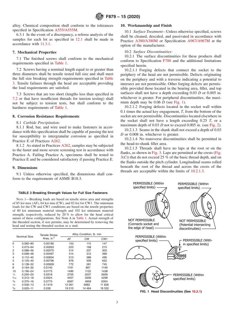
FIG. 1 Head Discontinuities (See 10.2.1)
F879 − 15 (2020)
tests are required, Supplementary Requirement S5 must be
specified in the inquiry and order, except as noted in 11.4.2.
11.4.2 Products that have been hot worked shall be solution
annealed and tested to determine freedom from precipitated
carbides. Not less than one corrosion test shall be made from
each lot. Corrosion tests shall be performed in accordance with
Practices A262, Practices A or E as applicable.
12. Test Methods
FIG. 2 Socket Discontinuities (See 10.2.1) 12.1 Chemical Analysis—The chemical composition shall
be determined in accordance with Test Method A751.
12.1.1 The fastener manufacturer may accept the chemical
11. Number of Tests
analysis of each heat of raw material purchased and reported on
the raw material certification furnished by the raw material
11.1 The requirements of this specification shall be met in
producer. The fastener manufacturer is not required to do any
continuous mass production for stock and the manufacturer
further chemical analysis testing provided that precise heat lot
shall make sample inspections to ensure that the product
conforms to the specified requirements. Additional tests of traceability has been maintained throughout the manufacturing
process on each lot of fasteners produced and delivered.
individual shipments of fasteners are not ordinarily necessary.
A record of the individual heat of steel in each lot shall be
12.2 Mechanical Tests:
maintained. The containers shall be coded to permit identifi-
12.2.1 Screws tested for axial strength, screw extension, or
cation of the lot.
hardness shall be tested in accordance with the methods
described in Test Methods F606/F606M and of this specifica-
11.2 When specified in the purchase order, the manufacturer
shall furnish a test report of the last complete set of chemi
...
This document is not an ASTM standard and is intended only to provide the user of an ASTM standard an indication of what changes have been made to the previous version. Because
it may not be technically possible to adequately depict all changes accurately, ASTM recommends that users consult prior editions as appropriate. In all cases only the current version
of the standard as published by ASTM is to be considered the official document.
Designation: F879 − 15 F879 − 15 (Reapproved 2020)
Standard Specification for
Stainless Steel Socket Button and Flat Countersunk Head
Cap Screws
This standard is issued under the fixed designation F879; the number immediately following the designation indicates the year of original
adoption or, in the case of revision, the year of last revision. A number in parentheses indicates the year of last reapproval. A superscript
epsilon (´) indicates an editorial change since the last revision or reapproval.
This standard has been approved for use by agencies of the U.S. Department of Defense.
1. Scope*
1.1 This specification covers the chemical and mechanical requirements for stainless steel inch hexagon socket button (SBHCS)
and flat countersunk (SFHCS) head cap screws with nominal thread 0.060 through 0.625 in. intended for use in applications
requiring general corrosion resistance.
1.2 Two groups of austenitic stainless steel alloys and three conditions are covered. See Table 1 and Table 2.
1.3 Units—The values stated in inch-pound units are to be regarded as standard. No other units of measurement are included
in this standard.
1.4 The following precautionary caveat pertains only to the test method portion, Section 12, of this specification: This standard
does not purport to address all of the safety concerns, if any, associated with its use. It is the responsibility of the user of this
standard to establish appropriate safety safety, health, and healthenvironmental practices and determine the applicability of
regulatory limitations prior to use.
1.5 This international standard was developed in accordance with internationally recognized principles on standardization
established in the Decision on Principles for the Development of International Standards, Guides and Recommendations issued
by the World Trade Organization Technical Barriers to Trade (TBT) Committee.
2. Referenced Documents
2.1 ASTM Standards:
A262 Practices for Detecting Susceptibility to Intergranular Attack in Austenitic Stainless Steels
A342/A342M Test Methods for Permeability of Weakly Magnetic Materials
A380/A380M Practice for Cleaning, Descaling, and Passivation of Stainless Steel Parts, Equipment, and Systems
A555/A555M Specification for General Requirements for Stainless Steel Wire and Wire Rods
A751 Test Methods, Practices, and Terminology for Chemical Analysis of Steel Products
A967/A967M Specification for Chemical Passivation Treatments for Stainless Steel Parts
D3951 Practice for Commercial Packaging
E18 Test Methods for Rockwell Hardness of Metallic Materials
E92 Test Methods for Vickers Hardness and Knoop Hardness of Metallic Materials
E384 Test Method for Microindentation Hardness of Materials
F593 Specification for Stainless Steel Bolts, Hex Cap Screws, and Studs
F606/F606M Test Methods for Determining the Mechanical Properties of Externally and Internally Threaded Fasteners,
Washers, Direct Tension Indicators, and Rivets
F788 Specification for Surface Discontinuities of Bolts, Screws, and Studs, Inch and Metric Series
F1470 Practice for Fastener Sampling for Specified Mechanical Properties and Performance Inspection
2.2 ASME Standard:
B 18.3 Socket Cap, Shoulder and Set Screws (Inch Series)
This specification is under the jurisdiction of ASTM Committee F16 on Fasteners and is the direct responsibility of Subcommittee F16.04 on Nonferrous Fasteners.
Current edition approved May 1, 2015April 1, 2020. Published July 2015April 2020. Originally approved in 1986. Last previous edition approved in 20122015 as
F879-12.-15. DOI: 10.1520/F0879-15.10.1520/F0879-15R20.
For referenced ASTM standards, visit the ASTM website, www.astm.org, or contact ASTM Customer Service at service@astm.org. For Annual Book of ASTM Standards
volume information, refer to the standard’s Document Summary page on the ASTM website.
Available from American Society of Mechanical Engineers (ASME), ASME International Headquarters, Two Park Ave., New York, NY 10016-5990, http://
www.asme.org.
*A Summary of Changes section appears at the end of this standard
Copyright © ASTM International, 100 Barr Harbor Drive, PO Box C700, West Conshohocken, PA 19428-2959. United States
F879 − 15 (2020)
TABLE 1 Mechanical Property Requirements
A B
Full Size Product Tests Machined Specimen Tests Core Hardness
Alloy
C
Alloy Group
Tensile Extension Tensile Yield Elongation
Condition Vickers Rockwell
min
Strength ksi Strength ksi Strength ksi % min
All AF 85 max 0.6D 85 max 55 max 40 210 max 95 HRB max
All CW 80 min 0.4D 80 min 40 min 25 150 min 50 HRA min
All CW1 102 min 0.4D 87 min 65 min 20 220 min 59 HRA min
A
Actual full-size testing of condition CW and CW1 may result in decreased tensile strength because of the head configuration (see Table 3). For fasteners with nominal
thread diameters larger than 0.625 in., the mechanical properties shall be agreed upon between the user and manufacturer.
B
Core hardness is only required when full-size product testing cannot be accomplished.
C
D denotes nominal thread size.
TABLE 2 Chemical Requirements
Composition, % maximum except as shown
Alloy UNS Manganese
Alloy Carbon Phosphorus Sulfur Silicon Chromium Nickel Copper Molybdenum
Group Designation
Austenitic Alloys
1 S30400 304 0.08 2.00 0.045 0.030 1.00 18.0 to 8.0 to 1.00 . . .
20.0 10.5
1 S30403 304L 0.030 2.00 0.045 0.030 1.00 18.0 to 8.0 to 1.00 . . .
20.0 12.0
1 S30500 305 0.12 2.00 0.045 0.030 1.00 17.0 to 10.5 to 1.00 . . .
19.0 13.0
1 S38400 384 0.08 2.00 0.045 0.030 1.00 15.0 to 17.0 to . . . . . .
17.0 19.0
1 S30430 18–9LW 0.10 2.00 0.045 0.030 1.00 17.0 to 8.0 to 3.0 to 4.0 . . .
19.0 10.0
1 S30433 302HQ 0.03 2.00 0.045 0.030 1.00 17.0 to 8.0 to 3.0 to 4.0 . . .
19.0 10.0
A
1 . 304J3 0.08 2.00 0.045 0.030 1.00 17.0 to 8.0 to 1.00 to . . .
19.0 10.5 3.00
2 S31600 316 0.08 2.00 0.045 0.030 1.00 16.0 to 10.0 to . . . 2.00 to 3.0
18.0 14.0
2 S31603 316L 0.03 2.00 0.045 0.030 1.00 16.0 to 10.0 to . . . 2.00 to 3.0
18.0 14.0
A
304J3 from JIS G 4309.
2.3 JIS Standard:
JIS G 4309 Stainless Steel Wires
3. Classification
3.1 The designation of the alloy group and condition of this specification shall be consistent with the stainless steel designations
in Specification F593.
3.2 Screws shall be designated by group and condition (for example, F879 Group 1 Condition AF).
4. Ordering Information
4.1 Orders for material under this specification shall include the following information:
4.1.1 Quantity (number of pieces of each item).
4.1.2 Name of the screw, SBHCS or SFHCS.
4.1.3 Dimensions, including nominal thread designation, thread pitch, and nominal screw length (inches). A standard part
number may be used for this definition.
4.1.4 Alloy group and condition.
4.1.5 Certification, if required (see Section 15).
4.1.6 ASTM specification and year of issue.
4.1.7 Any special or supplemental requirements (see Supplementary Requirements S1 through S6).
5. Materials and Manufacture
5.1 Screws shall be formed by upsetting or extruding, or both.
5.2 Screws shall be roll threaded.
Available from Japanese Industrial Standards Committee (JIS) 1-3-1 Kasumigaseki, Chiyoda-ku, Tokyo 100-8901, JAPAN. http://www.jisc.go.jp
F879 − 15 (2020)
5.3 Heat Treatment—Austenitic alloys Condition AF screws, following manufacture, shall be annealed by heating to 1900 6
50°F50 °F to obtain maximum corrosion resistance and minimum permeability. The screws shall be held for a sufficient time at
temperature, then cooled at a rate sufficient to prevent precipitation of the carbide and provide the properties specified in Table 1.
5.4 When Condition CW or CW1 is specified, the austenitic alloys shall be annealed as specified in 5.3, generally by the raw
material manufacturer, then cold worked to develop specific properties.
6. Chemical Composition
6.1 The chemical composition of the screws shall conform to the requirements of Table 2.
6.2 Unless otherwise specified in the inquiry and purchase order (see Supplementary Requirement S2), the choice of an alloy
from within a group shall be that of the fastener manufacturer as determined by his fabrication methods and material availability.
The specific alloy from within a group used by the manufacturer shall be clearly identified on all certification required in the
purchase order.
6.3 When chemical analysis is performed by the purchaser using finished fasteners, the chemical composition obtained shall
conform to the limits specified in Table 2 for the specific alloy. Chemical composition shall conform to the tolerances specified
in Specification A555/A555M.
6.3.1 In the event of a discrepancy, a referee analysis of the samples for each lot as specified in 12.1 shall be made in accordance
with 11.3.1.
7. Mechanical Properties
7.1 The finished screws shall conform to the mechanical requirements specified in Table 1.
7.2 Screws having a nominal length equal to or greater than three diameters shall be tensile tested full size and shall meet the
full size breaking strength requirements specified in Table 3. Tensile failures through the head are acceptable providing the load
requirements are satisfied.
7.3 Screws that are too short (lengths less than specified in 7.2 or that have insufficient threads for tension testing) shall not be
subject to tension tests, but shall conform to the hardness requirements of Table 1.
8. Corrosion Resistance Requirements
8.1 Carbide Precipitation:
8.1.1 Rod, bar, and wire used to make fasteners in accordance with this specification shall be capable of passing the test for
susceptibility to intergranular corrosion as specified in Practice E of Practices A262.
8.1.2 As stated in Practices A262, samples may be subjected to the faster and more severe screening test in accordance with
Practice A. Failing Practice A, specimens shall be tested to Practice E and be considered satisfactory if passing Practice E.
TABLE 3 Breaking Strength Values for Full Size Fasteners
NOTE 1—Breaking loads are based on tensile stress area and strengths
of 85 ksi max (AF), 64 ksi min (CW), and 82 ksi for CW1. The minimum
loads for the CW and CW1 conditions are based on the tensile properties
of 80 ksi minimum material strength and 102 ksi minimum material
strength, respectively, reduced by 20 % to allow for the head critical
nature of these configurations. See Note A in Table 1. Actual strength of
the threaded section, if size permits, may be determined by removing the
head and testing the threaded section as a stud.
Alloy Condition, lb. min
Tensile Stress
Nominal Size
Area, in.
AF CW CW1
0 0.060–80 0.00180 153 115 147
1 0.073–64 0.00263 223 168 215
2 0.086–56 0.00370 314 237 303
3 0.099–48 0.00487 414 312 399
4 0.112–40 0.00604 513 386 495
5 0.125–40 0.00796 676 509 652
6 0.138–32 0.00909 772 581 745
8 0.164–32 0.0140 1191 897 1149
10 0.190–24 0.0175 1490 1122 1438
⁄4 0.250–20 0.0318 2705 2037 2609
⁄16 0.312–18 0.0524 4457 3356 4299
⁄8 0.375–16 0.0775 6587 4959 6354
⁄2 0.500–13 0.1419 12 061 9082 11 636
⁄8 0.625–11 0.226 19 210 14 464 18 532
F879 − 15 (2020)
9. Dimensions
9.1 Unless otherwise specified, the dimensions shall conform to the requirements of ASME B18.3.
10. Workmanship and Finish
10.1 Surface Treatment—Unless otherwise specified, screws shall be cleaned, descaled, and passivated in accordance with
Practice A380/A380M or Specification A967/A967M at the option of the manufacturer.
10.2 Surface Discontinuities:
10.2.1 The surface discontinuities for these products shall conform to Specification F788 and the additional limitations specified
herein.
10.2.1.1 Forging defects that connect the socket to the periphery of the head are not permissible. Defects originating on the
periphery and with a traverse indicating a potential to intersect are not permissible. Other forging defects are permissible provided
those located in the bearing area, fillet, and top surfaces shall not have a depth exceeding 0.03 D or 0.005 in. whichever is greater.
For peripheral discontinuities, the maximum depth may be 0.06 D (see Fig. 1).
10.2.1.2 Forging defects located in the socket wall within 0.1 times the actual key engagement, T, from the bottom of the socket
are not permissible. Discontinuities located elsewhere in the socket shall not have a length exceeding 0.25 T, or a maximum depth
of 0.03 D not to exceed 0.005 in. (see Fig. 2).
10.2.1.3 Seams in the shank shall not exceed a depth of 0.03 D or 0.008 in. whichever is greater.
10.2.1.4 No transverse discontinuities shall be permitted in the head-to-shank fillet area.
10.2.1.5 Threads shall have no laps at the root or on the flanks, as shown in Fig. 3. Laps are permitted at the crests (Fig. 3(C))
that do not exceed 25 % of the basic thread depth, and on the flanks outside the pitch cylinder. Longitudinal seams rolled beneath
the root of the thread and across the crests of the threads are acceptable within the limits of 10.2.1.3.
11. Number of Tests
11.1 The requirements of this specification shall be met in continuous mass production for stock and the manufacturer shall
make sample inspections to ensure that the product conforms to the specified requirements. Additional tests of individual shipments
of fasteners are not ordinarily necessary. A record of the individual heat of steel in each lot shall be maintained. The containers
shall be coded to permit identification of the lot.
11.2 When specified in the purchase order, the manufacturer shall furnish a test report of the last complete set of chemical
analysis and mechanical tests for each stock size in each shipment.
11.3 When tests of individual shipments are required, Supplementary Requirement S1 must be specified in the inquiry and order.
11.3.1 When the purchaser does not specify the sampling plan and basis of acceptance, the following shall apply:
FIG. 1 Head Discontinuities (See 10.2.1)
F879 − 15 (2020)
FIG. 2 Socket Discontinuities (See 10.2.1)
11.3.1.1 The lot, for purposes of selecting samples, shall consist of all products offered for inspection and testing at one time
that are of the same type, style, nominal diameter, thread pitch, nominal length, material, condition, and surface finish.
11.3.1.2 From each lot, samples shall be selected at random and tested for each requirement in accordance with the following:
Number of Pieces in Lot Number of Samples
800 and less 1
Over 800 to 8000, incl 2
Over 8000 to 22 000, incl 3
Over 22 000 5
11.3.1.3
...
Questions, Comments and Discussion
Ask us and Technical Secretary will try to provide an answer. You can facilitate discussion about the standard in here.