


ASTM F1973-13(2018)
(Specification)Standard Specification for Factory Assembled Anodeless Risers and Transition Fittings in Polyethylene (PE) and Polyamide 11 (PA11) and Polyamide 12 (PA12) Fuel Gas Distribution Systems
Standard Specification for Factory Assembled Anodeless Risers and Transition Fittings in Polyethylene (PE) and Polyamide 11 (PA11) and Polyamide 12 (PA12) Fuel Gas Distribution Systems
ABSTRACT
This specification covers requirements and test methods for the qualification of factory assembled anodeless risers and transition fittings, for use in polyethylene (PE), in sizes through NPS 8, and Polyamide 11 (PA11), in sizes through NPS 6, gas distribution systems. The bend radius, steel pipe thread, steel flanges, and gas pressure containing factory welding shall meet the requirements prescribed. Temperature cycling test, tensile pull test, leak test, and constant tensile load joint test shall be performed to meet the requirements prescribed.
SCOPE
1.1 This specification covers requirements and test methods for the qualification of factory assembled anodeless risers and transition fittings, for use in polyethylene (PE), in sizes through NPS 8, and Polyamide 11 (PA11) and Polyamide 12 (PA12), in sizes through NPS 6, gas distribution systems.
1.2 The test methods described are not intended to be routine quality control tests.
1.3 The values stated in inch-pound units are to be regarded as standard. The values given in parentheses are mathematical conversions to SI units that are provided for information only and are not considered standard.
1.4 Throughout this specification footnotes are provided for informational purposes and shall not be considered as requirements of this specification.
1.5 This international standard was developed in accordance with internationally recognized principles on standardization established in the Decision on Principles for the Development of International Standards, Guides and Recommendations issued by the World Trade Organization Technical Barriers to Trade (TBT) Committee.
General Information
Buy Standard
Standards Content (Sample)
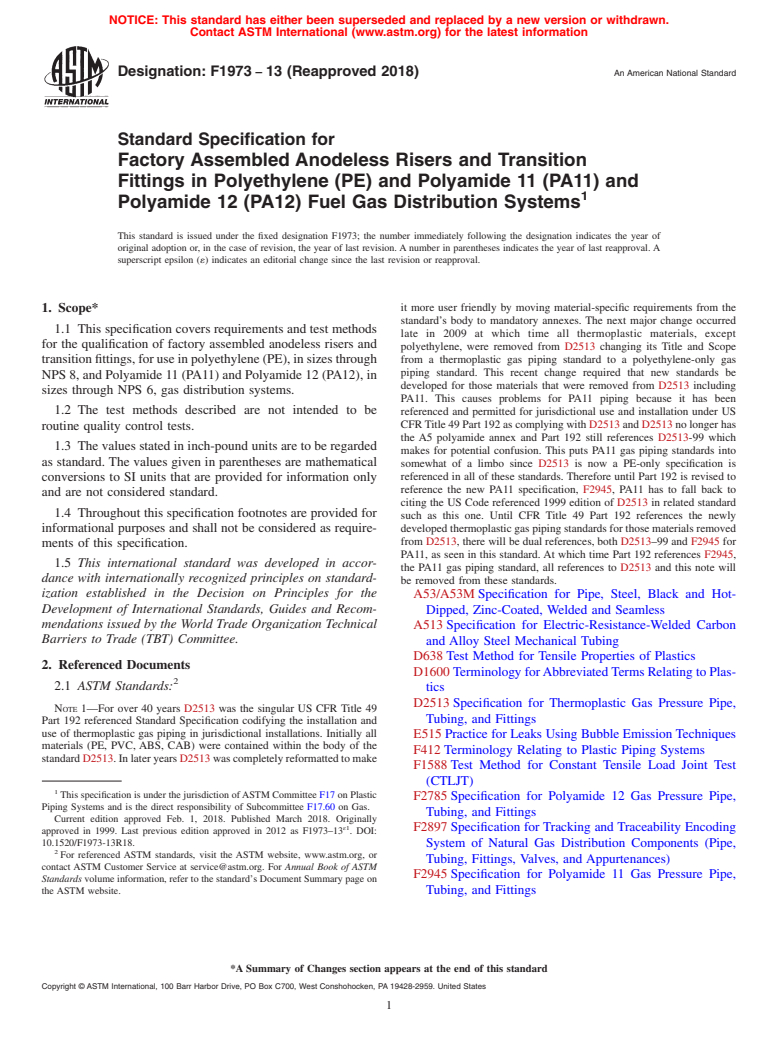
NOTICE: This standard has either been superseded and replaced by a new version or withdrawn.
Contact ASTM International (www.astm.org) for the latest information
Designation:F1973 −13 (Reapproved 2018) An American National Standard
Standard Specification for
Factory Assembled Anodeless Risers and Transition
Fittings in Polyethylene (PE) and Polyamide 11 (PA11) and
Polyamide 12 (PA12) Fuel Gas Distribution Systems
This standard is issued under the fixed designation F1973; the number immediately following the designation indicates the year of
original adoption or, in the case of revision, the year of last revision.Anumber in parentheses indicates the year of last reapproval.A
superscript epsilon (´) indicates an editorial change since the last revision or reapproval.
it more user friendly by moving material-specific requirements from the
1. Scope*
standard’s body to mandatory annexes. The next major change occurred
1.1 This specification covers requirements and test methods
late in 2009 at which time all thermoplastic materials, except
for the qualification of factory assembled anodeless risers and
polyethylene, were removed from D2513 changing its Title and Scope
transitionfittings,foruseinpolyethylene(PE),insizesthrough from a thermoplastic gas piping standard to a polyethylene-only gas
piping standard. This recent change required that new standards be
NPS8,andPolyamide11(PA11)andPolyamide12(PA12),in
developed for those materials that were removed from D2513 including
sizes through NPS 6, gas distribution systems.
PA11. This causes problems for PA11 piping because it has been
1.2 The test methods described are not intended to be referenced and permitted for jurisdictional use and installation under US
CFRTitle49Part192ascomplyingwithD2513andD2513nolongerhas
routine quality control tests.
the A5 polyamide annex and Part 192 still references D2513-99 which
1.3 Thevaluesstatedininch-poundunitsaretoberegarded
makes for potential confusion. This puts PA11 gas piping standards into
as standard. The values given in parentheses are mathematical
somewhat of a limbo since D2513 is now a PE-only specification is
referenced in all of these standards. Therefore until Part 192 is revised to
conversions to SI units that are provided for information only
reference the new PA11 specification, F2945, PA11 has to fall back to
and are not considered standard.
citing the US Code referenced 1999 edition of D2513 in related standard
1.4 Throughout this specification footnotes are provided for
such as this one. Until CFR Title 49 Part 192 references the newly
informational purposes and shall not be considered as require- developedthermoplasticgaspipingstandardsforthosematerialsremoved
from D2513, there will be dual references, both D2513–99 and F2945 for
ments of this specification.
PA11, as seen in this standard.At which time Part 192 references F2945,
1.5 This international standard was developed in accor-
the PA11 gas piping standard, all references to D2513 and this note will
dance with internationally recognized principles on standard-
be removed from these standards.
ization established in the Decision on Principles for the
A53/A53MSpecification for Pipe, Steel, Black and Hot-
Development of International Standards, Guides and Recom-
Dipped, Zinc-Coated, Welded and Seamless
mendations issued by the World Trade Organization Technical
A513Specification for Electric-Resistance-Welded Carbon
Barriers to Trade (TBT) Committee.
and Alloy Steel Mechanical Tubing
D638Test Method for Tensile Properties of Plastics
2. Referenced Documents
D1600TerminologyforAbbreviatedTermsRelatingtoPlas-
2.1 ASTM Standards:
tics
D2513Specification for Thermoplastic Gas Pressure Pipe,
NOTE 1—For over 40 years D2513 was the singular US CFR Title 49
Tubing, and Fittings
Part 192 referenced Standard Specification codifying the installation and
use of thermoplastic gas piping in jurisdictional installations. Initially all
E515Practice for Leaks Using Bubble EmissionTechniques
materials (PE, PVC, ABS, CAB) were contained within the body of the
F412Terminology Relating to Plastic Piping Systems
standardD2513.InlateryearsD2513wascompletelyreformattedtomake
F1588Test Method for Constant Tensile Load Joint Test
(CTLJT)
This specification is under the jurisdiction ofASTM Committee F17 on Plastic
F2785Specification for Polyamide 12 Gas Pressure Pipe,
Piping Systems and is the direct responsibility of Subcommittee F17.60 on Gas.
Tubing, and Fittings
Current edition approved Feb. 1, 2018. Published March 2018. Originally
ɛ1
F2897Specification for Tracking and Traceability Encoding
approved in 1999. Last previous edition approved in 2012 as F1973–13 . DOI:
10.1520/F1973-13R18. System of Natural Gas Distribution Components (Pipe,
For referenced ASTM standards, visit the ASTM website, www.astm.org, or
Tubing, Fittings, Valves, and Appurtenances)
contact ASTM Customer Service at service@astm.org. For Annual Book of ASTM
F2945Specification for Polyamide 11 Gas Pressure Pipe,
Standards volume information, refer to the standard’s Document Summary page on
the ASTM website. Tubing, and Fittings
*A Summary of Changes section appears at the end of this standard
Copyright © ASTM International, 100 Barr Harbor Drive, PO Box C700, West Conshohocken, PA 19428-2959. United States
F1973−13 (2018)
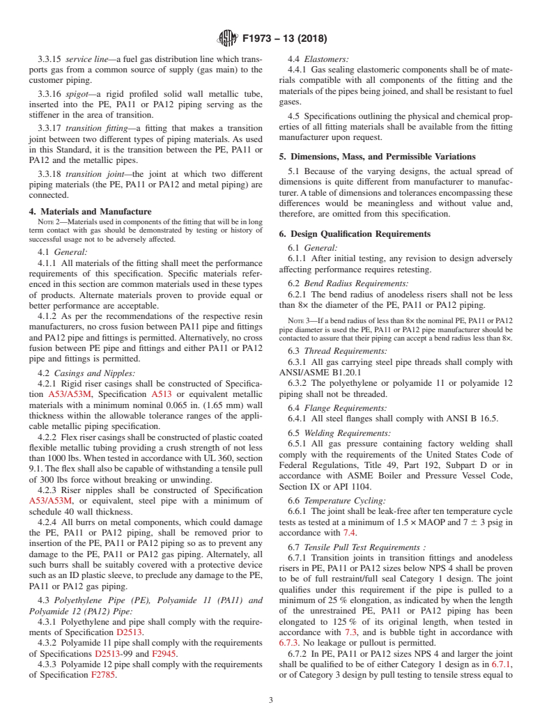
2.2 Federal Standard: 3.3.3 anodeless riser, flex design—an anodeless riser where
CFR Title 49 Part 192Transportation of Natural and Other the rise leg is a transition fitting which is fabricated to an
Gas By Pipeline: Minimum Federal Safety Standards anodeless flex riser casing which is field bent to form the base
leg.
2.3 ANSI Standards:
ANSI B 31.8Gas Transmission and Distribution Piping
3.3.3.1 Discussion—Anodeless flex risers usually require a
Systems
riser bracket attached to a rigid supporting member to avoid
ANSI/ASME B1.20.1 Pipe Threads, General Purpose meter set loads from being transmitted to the thermoplastic
(inch)
service line.
ANSI B 16.5Steel Pipe Flanges, Flanged Fittings
3.3.4 anodeless riser nipple—the metallic, aboveground,
2.4 ASME Standard:
gas carrying pipe or fitting portion of an anodeless riser.
ASME Boiler and Pressure Vessel Code
3.3.5 anodeless riser rigid riser casing—the metallic, non-
2.5 API Standard:
gas carrying protective outer sleeve portion of an anodeless
API 1104Standard for Welding Pipelines and Related Fa-
riser.
cilities
2.6 UL Standard: 3.3.6 anodeless riser, rigid, straight and prebent—ananode-
UL 360Flexible Metal Hose lessriserwhichisproducedstraightorfactoryprebent,usually
90°, thus defining rise leg and base leg dimensions.
2.7 PPI Standard:
PPI TR-4PPI Listing of Hydrostatic Design Bases (HDB),
3.3.7 base leg—the steel horizontal portion of an anodeless
Pressure Design Bases (PDB) and Minimum Required
riser measured from the centerline of vertical.
Strength (MRS) Ratings for Thermoplastic Piping Mate-
3.3.8 Category 1—a transition joint which provides for
rials or Pipe
pressure tightness and resistance to end loads sufficient to
cause no less than 25% elongation of the PE, PA11 or PA12
3. Terminology
piping as described in this standard.
3.1 The gas industry terminology used in this specification
isinaccordancewithANSIB31.8ortheUnitedStatesCFR49 3.3.9 Category 3—a transition joint which provides for
Part 192, unless otherwise indicated. pressure tightness and resistance to end loads greater than the
3.1.1 The term “pipe” used herein refers to both “pipe” and maximumthermalstressthatwouldbeproducedbyatempera-
“tubing” unless specifically stated otherwise. ture change of 100°F (55°C).
3.1.2 The term “gas” used herein refers to any fuel gas
3.3.10 grade level marking—a marking, tape or label ap-
unless specifically stated otherwise.
plied to the riser to identify the point at which the transition
3.2 Definitions—Definitions are in accordance with Defini-
from PE, PA11 or PA12 gas carrier to metallic gas carrier
tions F412 unless otherwise specified. Abbreviations are in
occurs. This marking assists the installer in determining the
accordance withAbbreviations D1600 unless otherwise speci-
grade level of the installation.
fied.
3.3.11 insert stiffener—a rigid, non-split, solid wall tube
3.3 Definitions:
which is inserted into PE, PA11 or PA12 piping to support
3.3.1 anodeless flex riser casing—a flexible, plastic coated,
compression loads in the area of the transition joint.
metallic,non-gascarrying,protectiveoutersleeveportionofan
3.3.12 joint—the location at which two or more pieces of
anodeless riser which is sometimes selected as an alternate to
pipe or a pipe and a fitting are connected.
rigid riser casings.
3.3.13 MAOP—the maximum allowable operating pressure
3.3.2 anodeless riser—a type of transition fitting which is
of the fuel gas piping system, in psig, as determined in
designedtotransportgasfromanundergroundpolyethyleneor
accordance with US DOT CFR, Title 49, Part 192.121 and as
polyamide 11 or polyamide 12 service line to above-ground
represented in the following:
steel piping. In an anodeless riser, the polyethylene or poly-
amide 11 or polyamide 12 pipe is always the gas carrier, at
MAOP 5 P 52 3S/ R 21 3f (1)
~ !
D
least, in the below ground section.
where:
S = TheThermoplasticmaterials’HDBaspublishedinthe
Available from DLA Document Services, Building 4/D, 700 Robbins Ave.,
Plastics Pipe Institute PPI TR 4 publication,
Philadelphia, PA 19111-5094, http://quicksearch.dla.mil.
R = The pipe’s dimension ratio determined by dividing the
Available fromAmerican National Standards Institute (ANSI), 25 W. 43rd St.,
pipe’s specified nominal outside diameter by the pipes
4th Floor, New York, NY 10036, http://www.ansi.org.
specified nominal wall thickness, and
Available from American Society of Mechanical Engineers (ASME), ASME
International Headquarters, Three Park Ave., New York, NY 10016-5990, http:// f = the design (derating) factor for thermoplastic fuel gas
D
www.asme.org.
pipingassetbytheauthorityhavingjurisdiction.Inthe
Available from American Petroleum Institute (API), 1220 L. St., NW,
UnitedStatesthedesignfactoriscitedinCFRTitle49
Washington, DC 20005-4070, http://www.api.org.
Part 192.121.
Available from Underwriters Laboratories (UL), 333 Pfingsten Rd.,
Northbrook, IL 60062-2096, http://www.ul.com.
3.3.14 rise leg—the vertical portion of an anodeless riser
Available from Plastics Pipe Institute (PPI), 105 Decker Court, Suite 825,
Irving, TX 75062, http://www.plasticpipe.org. measured from the centerline of horizontal.
F1973−13 (2018)
3.3.15 service line—a fuel gas distribution line which trans- 4.4 Elastomers:
ports gas from a common source of supply (gas main) to the 4.4.1 Gas sealing elastomeric components shall be of mate-
customer piping. rials compatible with all components of the fitting and the
materialsofthepipesbeingjoined,andshallberesistanttofuel
3.3.16 spigot—a rigid profiled solid wall metallic tube,
gases.
inserted into the PE, PA11 or PA12 piping serving as the
stiffener in the area of transition.
4.5 Specificationsoutliningthephysicalandchemicalprop-
erties of all fitting materials shall be available from the fitting
3.3.17 transition fitting—a fitting that makes a transition
manufacturer upon request.
joint between two different types of piping materials.As used
in this Standard, it is the transition between the PE, PA11 or
5. Dimensions, Mass, and Permissible Variations
PA12 and the metallic pipes.
5.1 Because of the varying designs, the actual spread of
3.3.18 transition joint—the joint at which two different
dimensions is quite different from manufacturer to manufac-
piping materials (the PE, PA11 or PA12 and metal piping) are
turer.Atableofdimensionsandtolerancesencompassingthese
connected.
differences would be meaningless and without value and,
4. Materials and Manufacture
therefore, are omitted from this specification.
NOTE2—Materialsusedincomponentsofthefittingthatwillbeinlong
term contact with gas should be demonstrated by testing or history of
6. Design Qualification Requirements
successful usage not to be adversely affected.
6.1 General:
4.1 General:
6.1.1 After initial testing, any revision to design adversely
4.1.1 All materials of the fitting shall meet the performance
affecting performance requires retesting.
requirements of this specification. Specific materials refer-
6.2 Bend Radius Requirements:
enced in this section are common materials used in these types
6.2.1 The bend radius of anodeless risers shall not be less
of products. Alternate materials proven to provide equal or
than 8× the diameter of the PE, PA11 or PA12 piping.
better performance are acceptable.
4.1.2 As per the recommendations of the respective resin
NOTE3—Ifabendradiusoflessthan8×thenominalPE,PA11orPA12
manufacturers, no cross fusion between PA11 pipe and fittings
pipe diameter is used the PE, PA11 or PA12 pipe manufacturer should be
and PA12 pipe and fittings is permitted.Alternatively, no cross
contactedtoassurethattheirpipingcanacceptabendradiuslessthan8×.
fusion between PE pipe and fittings and either PA11 or PA12
6.3 Thread Requirements:
pipe and fittings is permitted.
6.3.1 All gas carrying steel pipe threads shall comply with
ANSI/ASME B1.20.1
4.2 Casings and Nipples:
4.2.1 Rigid riser casings shall be constructed of Specifica- 6.3.2 The polyethylene or polyamide 11 or polyamide 12
piping shall not be threaded.
tion A53/A53M, Specification A513 or equivalent metallic
materials with a minimum nominal 0.065 in. (1.65 mm) wall
6.4 Flange Requirements:
thickness within the allowable tolerance ranges of the appli-
6.4.1 All steel flanges shall comply with ANSI B 16.5.
cable metallic piping specification.
6.5 Welding Requirements:
4.2.2 Flexrisercasingsshallbeconstructedofplasticcoated
6.5.1 All gas pressure containing factory welding shall
flexible metallic tubing providing a crush strength of not less
comply with the requirements of the United States Code of
than1000lbs.WhentestedinaccordancewithUL360,section
Federal Regulations, Title 49, Part 192, Subpart D or in
9.1.Theflexshallalsobecapableofwithstandingatensilepull
accordance with ASME Boiler and Pressure Vessel Code,
of 300 lbs force without breaking or unwinding.
Section IX or API 1104.
4.2.3 Riser nipples shall be constructed of Specification
6.6 Temperature Cycling:
A53/A53M, or equivalent, steel pipe with a minimum of
schedule 40 wall thickness. 6.6.1 Thejointshallbeleak-freeaftertentemperaturecycle
tests as tested at a minimum of 1.5 × MAOPand 7 6 3 psig in
4.2.4 All burrs on metal components, which could damage
the PE, PA11 or PA12 piping, shall be removed prior to accordance with 7.4.
insertion of the PE, PA11 or PA12 piping so as to prevent any
6.7 Tensile Pull Test Requirements :
damage to the PE, PA11 or PA12 gas piping. Alternately, all
6.7.1 Transition joints in transition fittings and anodeless
such burrs shall be suitably covered with a protective device
risers in PE
...
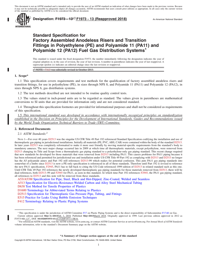
This document is not an ASTM standard and is intended only to provide the user of an ASTM standard an indication of what changes have been made to the previous version. Because
it may not be technically possible to adequately depict all changes accurately, ASTM recommends that users consult prior editions as appropriate. In all cases only the current version
of the standard as published by ASTM is to be considered the official document.
´1
Designation: F1973 − 13 F1973 − 13 (Reapproved 2018) An American National Standard
Standard Specification for
Factory Assembled Anodeless Risers and Transition
Fittings in Polyethylene (PE) and Polyamide 11 (PA11) and
Polyamide 12 (PA12) Fuel Gas Distribution Systems
This standard is issued under the fixed designation F1973; the number immediately following the designation indicates the year of
original adoption or, in the case of revision, the year of last revision. A number in parentheses indicates the year of last reapproval. A
superscript epsilon (´) indicates an editorial change since the last revision or reapproval.
ε NOTE—7.4.3 was editorially revised in October 2013.
1. Scope*
1.1 This specification covers requirements and test methods for the qualification of factory assembled anodeless risers and
transition fittings, for use in polyethylene (PE), in sizes through NPS 8, and Polyamide 11 (PA11) and Polyamide 12 (PA12), in
sizes through NPS 6, gas distribution systems.
1.2 The test methods described are not intended to be routine quality control tests.
1.3 The values stated in inch-pound units are to be regarded as standard. The values given in parentheses are mathematical
conversions to SI units that are provided for information only and are not considered standard.
1.4 Throughout this specification footnotes are provided for informational purposes and shall not be considered as requirements
of this specification.
1.5 This international standard was developed in accordance with internationally recognized principles on standardization
established in the Decision on Principles for the Development of International Standards, Guides and Recommendations issued
by the World Trade Organization Technical Barriers to Trade (TBT) Committee.
2. Referenced Documents
2.1 ASTM Standards:
NOTE 1—For over 40 years D2513 was the singular US CFR Title 49 Part 192 referenced Standard Specification codifying the installation and use of
thermoplastic gas piping in jurisdictional installations. Initially all materials (PE, PVC, ABS, CAB) were contained within the body of the standard D2513.
In later years D2513 was completely reformatted to make it more user friendly by moving material-specific requirements from the standard’s body to
mandatory annexes. The next major change occurred late in 2009 at which time all thermoplastic materials, except polyethylene, were removed from
D2513 changing its Title and Scope from a thermoplastic gas piping standard to a polyethylene-only gas piping standard. This recent change required
that new standards be developed for those materials that were removed from D2513 including PA11. This causes problems for PA11 piping because it
has been referenced and permitted for jurisdictional use and installation under US CFR Title 49 Part 192 as complying with D2513 and D2513 no longer
has the A5 polyamide annex and Part 192 still references D2513-99 which makes for potential confusion. This puts PA11 gas piping standards into
somewhat of a limbo since D2513 is now a PE-only specification is referenced in all of these standards. Therefore until Part 192 is revised to reference
the new PA11 specification, F2945, PA11 has to fall back to citing the US Code referenced 1999 edition of D2513 in related standard such as this one.
Until CFR Title 49 Part 192 references the newly developed thermoplastic gas piping standards for those materials removed from D2513, there will be
dual references, both D2513–99 and F2945 for PA11, as seen in this standard. At which time Part 192 references F2945, the PA11 gas piping standard,
all references to D2513 and this note will be removed from these standards.
A53/A53M Specification for Pipe, Steel, Black and Hot-Dipped, Zinc-Coated, Welded and Seamless
A513 Specification for Electric-Resistance-Welded Carbon and Alloy Steel Mechanical Tubing
D638 Test Method for Tensile Properties of Plastics
D1600 Terminology for Abbreviated Terms Relating to Plastics
D2513 Specification for Thermoplastic Gas Pressure Pipe, Tubing, and Fittings
E515 Practice for Leaks Using Bubble Emission Techniques
F412 Terminology Relating to Plastic Piping Systems
This specification is under the jurisdiction of ASTM Committee F17 on Plastic Piping Systems and is the direct responsibility of Subcommittee F17.60 on Gas.
Current edition approved May 1, 2013Feb. 1, 2018. Published May 2013March 2018. Originally approved in 1999. Last previous edition approved in 2012 as
ɛ1
F1973–12.–13 . DOI: 10.1520/F1973-13.10.1520/F1973-13R18.
For referenced ASTM standards, visit the ASTM website, www.astm.org, or contact ASTM Customer Service at service@astm.org. For Annual Book of ASTM Standards
volume information, refer to the standard’s Document Summary page on the ASTM website.
*A Summary of Changes section appears at the end of this standard
Copyright © ASTM International, 100 Barr Harbor Drive, PO Box C700, West Conshohocken, PA 19428-2959. United States
F1973 − 13 (2018)
F1588 Test Method for Constant Tensile Load Joint Test (CTLJT)
F2785 Specification for Polyamide 12 Gas Pressure Pipe, Tubing, and Fittings
F2897 Specification for Tracking and Traceability Encoding System of Natural Gas Distribution Components (Pipe, Tubing,
Fittings, Valves, and Appurtenances)
F2945 Specification for Polyamide 11 Gas Pressure Pipe, Tubing, and Fittings
2.2 Federal Standard:
CFR Title 49 Part 192 Transportation of Natural and Other Gas By Pipeline: Minimum Federal Safety Standards
2.3 ANSI Standards:
ANSI B 31.8 Gas Transmission and Distribution Piping Systems
ANSI/ASME B1.20.1 Pipe Threads, General Purpose (inch)
ANSI B 16.5 Steel Pipe Flanges, Flanged Fittings
2.4 ASME Standard:
ASME Boiler and Pressure Vessel Code
2.5 API Standard:
API 1104 Standard for Welding Pipelines and Related Facilities
2.6 UL Standard:
UL 360 Flexible Metal Hose
2.7 PPI Standard:
PPI TR-4 PPI Listing of Hydrostatic Design Bases (HDB), Pressure Design Bases (PDB) and Minimum Required Strength
(MRS) Ratings for Thermoplastic Piping Materials or Pipe
3. Terminology
3.1 The gas industry terminology used in this specification is in accordance with ANSI B31.8 or the United States CFR 49 Part
192, unless otherwise indicated.
3.1.1 The term “pipe” used herein refers to both “pipe” and “tubing” unless specifically stated otherwise.
3.1.2 The term “gas” used herein refers to any fuel gas unless specifically stated otherwise.
3.2 Definitions—Definitions are in accordance with Definitions F412 unless otherwise specified. Abbreviations are in
accordance with Abbreviations D1600 unless otherwise specified.
3.3 Definitions:
3.3.1 anodeless flex riser casing—a flexible, plastic coated, metallic, non-gas carrying, protective outer sleeve portion of an
anodeless riser which is sometimes selected as an alternate to rigid riser casings.
3.3.2 anodeless riser—a type of transition fitting which is designed to transport gas from an underground polyethylene or
polyamide 11 or polyamide 12 service line to above-ground steel piping. In an anodeless riser, the polyethylene or polyamide 11
or polyamide 12 pipe is always the gas carrier, at least, in the below ground section.
3.3.3 anodeless riser, flex design—an anodeless riser where the rise leg is a transition fitting which is fabricated to an anodeless
flex riser casing which is field bent to form the base leg.
Available from Standardization Documents Order Desk, DODSSP, Bldg. 4, Section D, DLA Document Services, Building 4/D, 700 Robbins Ave., Philadelphia, PA
19111-5098, http://dodssp.daps.dla.mil.19111-5094, http://quicksearch.dla.mil.
Available from American National Standards Institute (ANSI), 25 W. 43rd St., 4th Floor, New York, NY 10036, http://www.ansi.org.
Available from American Society of Mechanical Engineers (ASME), ASME International Headquarters, Three Park Ave., New York, NY 10016-5990, http://
www.asme.org.
Available from American Petroleum Institute (API), 1220 L. St., NW, Washington, DC 20005-4070, http://www.api.org.
Available from Underwriters Laboratories (UL), 333 Pfingsten Rd., Northbrook, IL 60062-2096, http://www.ul.com.
Available from Plastics Pipe Institute (PPI), 105 Decker Court, Suite 825, Irving, TX 75062, http://www.plasticpipe.org.
3.3.3.1 Discussion—
Anodeless flex risers usually require a riser bracket attached to a rigid supporting member to avoid meter set loads from being
transmitted to the thermoplastic service line.
3.3.4 anodeless riser nipple—the metallic, aboveground, gas carrying pipe or fitting portion of an anodeless riser.
3.3.5 anodeless riser rigid riser casing—the metallic, non-gas carrying protective outer sleeve portion of an anodeless riser.
3.3.6 anodeless riser, rigid, straight and prebent—an anodeless riser which is produced straight or factory prebent, usually 90°,
thus defining rise leg and base leg dimensions.
3.3.7 base leg—the steel horizontal portion of an anodeless riser measured from the centerline of vertical.
3.3.8 Category 1—a transition joint which provides for pressure tightness and resistance to end loads sufficient to cause no less
than 25 % elongation of the PE, PA11 or PA12 piping as described in this standard.
F1973 − 13 (2018)
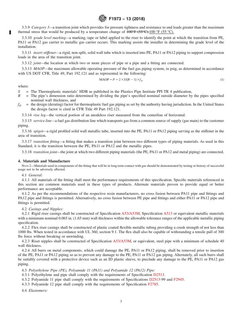
3.3.9 Category 3—a transition joint which provides for pressure tightness and resistance to end loads greater than the maximum
thermal stress that would be produced by a temperature change of 100°F (55°C).100 °F (55 °C).
3.3.10 grade level marking—a marking, tape or label applied to the riser to identify the point at which the transition from PE,
PA11 or PA12 gas carrier to metallic gas carrier occurs. This marking assists the installer in determining the grade level of the
installation.
3.3.11 insert stiffener—a rigid, non-split, solid wall tube which is inserted into PE, PA11 or PA12 piping to support compression
loads in the area of the transition joint.
3.3.12 joint—the location at which two or more pieces of pipe or a pipe and a fitting are connected.
3.3.13 MAOP—the maximum allowable operating pressure of the fuel gas piping system, in psig, as determined in accordance
with US DOT CFR, Title 49, Part 192.121 and as represented in the following:
MAOP 5 P 5 23S/~R 2 1!3f (1)
D
where:
S = The Thermoplastic materials’ HDB as published in the Plastics Pipe Institute PPI TR 4 publication,
R = The pipe’s dimension ratio determined by dividing the pipe’s specified nominal outside diameter by the pipes specified
nominal wall thickness, and
f = the design (derating) factor for thermoplastic fuel gas piping as set by the authority having jurisdiction. In the United States
D
the design factor is cited in CFR Title 49 Part 192.121.
3.3.14 rise leg—the vertical portion of an anodeless riser measured from the centerline of horizontal.
3.3.15 service line—a fuel gas distribution line which transports gas from a common source of supply (gas main) to the customer
piping.
3.3.16 spigot—a rigid profiled solid wall metallic tube, inserted into the PE, PA11 or PA12 piping serving as the stiffener in the
area of transition.
3.3.17 transition fitting—a fitting that makes a transition joint between two different types of piping materials. As used in this
Standard, it is the transition between the PE, PA11 or PA12 and the metallic pipes.
3.3.18 transition joint—the joint at which two different piping materials (the PE, PA11 or PA12 and metal piping) are connected.
4. Materials and Manufacture
NOTE 2—Materials used in components of the fitting that will be in long term contact with gas should be demonstrated by testing or history of successful
usage not to be adversely affected.
4.1 General:
4.1.1 All materials of the fitting shall meet the performance requirements of this specification. Specific materials referenced in
this section are common materials used in these types of products. Alternate materials proven to provide equal or better
performance are acceptable.
4.1.2 As per the recommendations of the respective resin manufacturers, no cross fusion between PA11 pipe and fittings and
PA12 pipe and fittings is permitted. Alternatively, no cross fusion between PE pipe and fittings and either PA11 or PA12 pipe and
fittings is permitted.
4.2 Casings and Nipples:
4.2.1 Rigid riser casings shall be constructed of Specification A53/A53M, Specification A513 or equivalent metallic materials
with a minimum nominal 0.065 in. (1.65 mm) wall thickness within the allowable tolerance ranges of the applicable metallic piping
specification.
4.2.2 Flex riser casings shall be constructed of plastic coated flexible metallic tubing providing a crush strength of not less than
1000 lbs. When tested in accordance with UL 360, section 9.1. The flex shall also be capable of withstanding a tensile pull of 300
lbs force without breaking or unwinding.
4.2.3 Riser nipples shall be constructed of Specification A53/A53M, or equivalent, steel pipe with a minimum of schedule 40
wall thickness.
4.2.4 All burrs on metal components, which could damage the PE, PA11 or PA12 piping, shall be removed prior to insertion
of the PE, PA11 or PA12 piping so as to prevent any damage to the PE, PA11 or PA12 gas piping. Alternately, all such burrs shall
be suitably covered with a protective device such as an ID plastic sleeve, to preclude any damage to the PE, PA11 or PA12 gas
piping.
4.3 Polyethylene Pipe (PE), Polyamide 11 (PA11) and Polyamide 12 (PA12) Pipe:
4.3.1 Polyethylene and pipe shall comply with the requirements of Specification D2513.
4.3.2 Polyamide 11 pipe shall comply with the requirements of Specifications D2513-99 and F2945.
4.3.3 Polyamide 12 pipe shall comply with the requirements of Specification F2785.
4.4 Elastomers:
F1973 − 13 (2018)
4.4.1 Gas sealing elastomeric components shall be of materials compatible with all components of the fitting and the materials
of the pipes being joined, and shall be resistant to fuel gases.
4.5 Specifications outlining the physical and chemical properties of all fitting materials shall be available from the fitting
manufacturer upon request.
5. Dimensions, Mass, and Permissible Variations
5.1 Because of the varying designs, the actual spread of dimensions is quite different from manufacturer to manufacturer. A table
of dimensions and tolerances encompassing these differences would be meaningless and without value and, therefore, are omitted
from this specification.
6. Design Qualification Requirements
6.1 General:
6.1.1 After initial testing, any revis
...
Questions, Comments and Discussion
Ask us and Technical Secretary will try to provide an answer. You can facilitate discussion about the standard in here.