


ASTM C1678-10(2015)
(Practice)Standard Practice for Fractographic Analysis of Fracture Mirror Sizes in Ceramics and Glasses
Standard Practice for Fractographic Analysis of Fracture Mirror Sizes in Ceramics and Glasses
SIGNIFICANCE AND USE
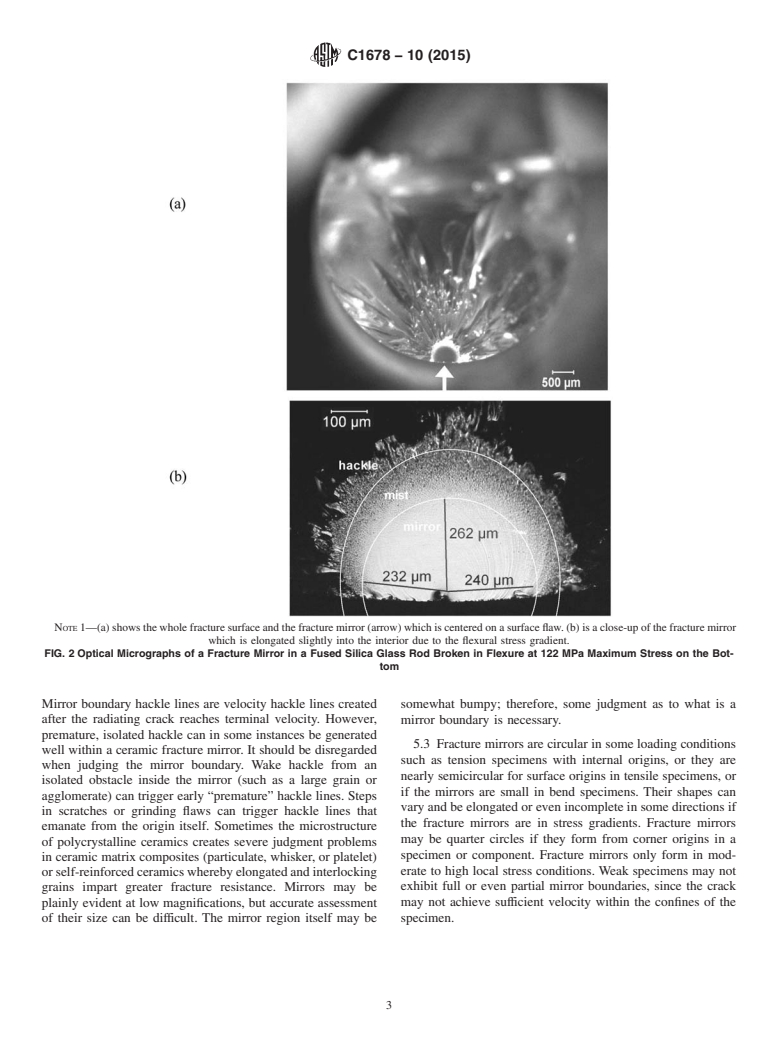
5.1 Fracture mirror size analysis is a powerful tool for analyzing glass and ceramic fractures. Fracture mirrors are telltale fractographic markings in brittle materials that surround a fracture origin as discussed in Practices C1256 and C1322. Fig. 1 shows a schematic with key features identified. Fig. 2 shows an example in glass. The fracture mirror region is very smooth and highly reflective in glasses, hence the name “fracture mirror.” In fact, high magnification microscopy reveals that, even within the mirror region in glasses, there are very fine features and escalating roughness as the crack advances away from the origin. These are submicrometer in size and hence are not discernable with an optical microscope. Early investigators interpreted fracture mirrors as having discrete boundaries including a “mirror-mist” boundary and also a “mist-hackle” boundary in glasses. These were also termed “inner mirror” or “outer mirror” boundaries, respectively. It is now known that there are no discrete boundaries corresponding to specific changes in the fractographic features. Surface roughness increases gradually from well within the fracture mirror to beyond the apparent boundaries. The boundaries were a matter of interpretation, the resolving power of the microscope, and the mode of viewing. In very weak specimens, the mirror may be larger than the specimen or component and the boundaries will not be present. σ = stress at the origin (MPa or ksi), R = fracture mirror radius (m or in), A = fracture mirror constant (MPa√m or ksi√in). Eq 1 is hereafter referred to as the “empirical stress – fracture mirror size relationship,” or “stress-mirror size relationship” for short. A review of the history of Eq 1, and fracture mirror analysis in general, may be found in Refs 1 and 2.
5.5 A, the “fracture mirror constant” (sometimes also known as the “mirror constant”) has units of stress intensity (MPa√m or ksi√in) and is considered by many to be a material property...
SCOPE
1.1 This practice pertains to the analysis and interpretation of fracture mirror sizes in brittle materials. Fracture mirrors (Fig. 1) are telltale fractographic markings that surround a fracture origin in brittle materials. The fracture mirror size may be used with known fracture mirror constants to estimate the stress in a fractured component. Alternatively, the fracture mirror size may be used in conjunction with known stresses in test specimens to calculate fracture mirror constants. The practice is applicable to glasses and polycrystalline ceramic laboratory test specimens as well as fractured components. The analysis and interpretation procedures for glasses and ceramics are similar, but they are not identical. Different optical microscopy examination techniques are listed and described, including observation angles, illumination methods, appropriate magnification, and measurement protocols. Guidance is given for calculating a fracture mirror constant and for interpreting the fracture mirror size and shape for both circular and noncircular mirrors including stress gradients, geometrical effects, and/or residual stresses. The practice provides figures and micrographs illustrating the different types of features commonly observed in and measurement techniques used for the fracture mirrors of glasses and polycrystalline ceramics.
Note 1: The initial flaw may grow stably to size ac prior to unstable fracture when the stress intensity reaches KIc. The mirror-mist radius is Ri, the mist-hackle radius is Ro, and the branching distance is Rb. These transitions correspond to the mirror constants, Ai, Ao, and Ab, respectively.
1.2 The values stated in SI units are to be regarded as standard. No other units of measurement are included in this standard.
1.3 This standard does not purport to address all of the safety concerns, if any, associated with its use. It is the responsibility of the user of this standard to est...
General Information
Buy Standard
Standards Content (Sample)
NOTICE: This standard has either been superseded and replaced by a new version or withdrawn.
Contact ASTM International (www.astm.org) for the latest information
Designation: C1678 − 10 (Reapproved 2015)
Standard Practice for
Fractographic Analysis of Fracture Mirror Sizes in Ceramics
and Glasses
This standard is issued under the fixed designation C1678; the number immediately following the designation indicates the year of
original adoption or, in the case of revision, the year of last revision. A number in parentheses indicates the year of last reapproval. A
superscript epsilon (´) indicates an editorial change since the last revision or reapproval.
1. Scope 2. Referenced Documents
1.1 This practice pertains to the analysis and interpretation 2.1 ASTM Standards:
of fracture mirror sizes in brittle materials. Fracture mirrors C1145 Terminology of Advanced Ceramics
(Fig. 1) are telltale fractographic markings that surround a C1256 Practice for Interpreting Glass Fracture Surface Fea-
fractureorigininbrittlematerials.Thefracturemirrorsizemay tures
be used with known fracture mirror constants to estimate the C1322 Practice for Fractography and Characterization of
stress in a fractured component. Alternatively, the fracture Fracture Origins in Advanced Ceramics
mirror size may be used in conjunction with known stresses in
3. Terminology
test specimens to calculate fracture mirror constants. The
practice is applicable to glasses and polycrystalline ceramic 3.1 Definitions: (See Fig. 1)
laboratory test specimens as well as fractured components.The 3.1.1 fracture mirror, n—as used in fractography of brittle
analysis and interpretation procedures for glasses and ceramics materials, a relatively smooth region in the immediate vicinity
are similar, but they are not identical. Different optical micros- of and surrounding the fracture origin C1145, C1322
copy examination techniques are listed and described, includ-
3.1.2 fracture origin, n—the source from which brittle
ing observation angles, illumination methods, appropriate
fracture commences. C1145, C1322
magnification, and measurement protocols. Guidance is given
3.1.3 hackle, n—as used in fractography of brittle materials,
for calculating a fracture mirror constant and for interpreting
alineorlinesonthecracksurfacerunninginthelocaldirection
the fracture mirror size and shape for both circular and
of cracking, separating parallel but noncoplanar portions of the
noncircular mirrors including stress gradients, geometrical
crack surface. C1145, C1322
effects, and/or residual stresses. The practice provides figures
3.1.4 mist, n—as used in fractography of brittle materials,
and micrographs illustrating the different types of features
markings on the surface of an accelerating crack close to its
commonly observed in and measurement techniques used for
effective terminal velocity, observable first as a misty appear-
the fracture mirrors of glasses and polycrystalline ceramics.
ance and with increasing velocity reveals a fibrous texture,
1.2 The values stated in SI units are to be regarded as
elongated in the direction of crack propagation. C1145, C1322
standard. No other units of measurement are included in this
3.2 Definitions of Terms Specific to This Standard:
standard.
(See Fig. 1)
1.3 This standard does not purport to address all of the
3.2.1 mirror-mist boundary in glasses, n—the periphery
safety concerns, if any, associated with its use. It is the
where one can discern the onset of mist around a glass fracture
responsibility of the user of this standard to establish appro-
mirror. This boundary corresponds to A, the inner mirror
i
priate safety and health practices and determine the applica-
constant.
bility of regulatory limitations prior to use.
3.2.2 mist-hackle boundary in glasses, n—the periphery
where one can discern the onset of systematic hackle around a
This practice is under the jurisdiction of ASTM Committee C28 on Advanced
Ceramics and is the direct responsibility of Subcommittee C28.03 on Physical
Properties and Non-Destructive Evaluation. For referenced ASTM standards, visit the ASTM website, www.astm.org, or
Current edition approved July 1, 2015. Published September 2015. Originally contact ASTM Customer Service at service@astm.org. For Annual Book of ASTM
approved in 2007. Last previous edition approved in 2010 as C1678 – 10. DOI: Standards volume information, refer to the standard’s Document Summary page on
10.1520/C1678-10R15. the ASTM website.
Copyright © ASTM International, 100 Barr Harbor Drive, PO Box C700, West Conshohocken, PA 19428-2959. United States
C1678 − 10 (2015)
NOTE 1—The initial flaw may grow stably to size a prior to unstable fracture when the stress intensity reaches K . The mirror-mist radius is R, the
c Ic i
mist-hackle radius is R , and the branching distance is R . These transitions correspond to the mirror constants, A,A , and A , respectively.
o b i o b
FIG. 1 Schematic of a Fracture Mirror Centered on a Surface Flaw of Initial Size (a)
glass fracture mirror. This boundary corresponds to A , the a fracture origin as discussed in Practices C1256 and C1322.
o
outer mirror constant. Fig. 1 shows a schematic with key features identified. Fig. 2
shows an example in glass. The fracture mirror region is very
3.2.3 mirror-hackle boundary in polycrystalline ceramics,,
smooth and highly reflective in glasses, hence the name
n—the periphery where one can discern the onset of systematic
“fracture mirror.” In fact, high magnification microscopy
new hackle and there is an obvious roughness change relative
reveals that, even within the mirror region in glasses, there are
to that inside a ceramic fracture mirror region. This boundary
very fine features and escalating roughness as the crack
corresponds toA , the outer mirror constant. Ignore premature
o
advances away from the origin. These are submicrometer in
hackle and/or isolated steps from microstructural irregularities
size and hence are not discernable with an optical microscope.
in the mirror or irregularities at the origin.
Early investigators interpreted fracture mirrors as having
-3/2
3.2.4 fracture mirror constant, n—(Fl ) an empirical ma-
discrete boundaries including a “mirror-mist” boundary and
terial constant that relates the fracture stress to the mirror
also a “mist-hackle” boundary in glasses. These were also
radius in glasses and ceramics.
termed “inner mirror” or “outer mirror” boundaries, respec-
tively. It is now known that there are no discrete boundaries
4. Summary of Practice
corresponding to specific changes in the fractographic features.
4.1 This practice provides guidance on the measurement
Surface roughness increases gradually from well within the
and interpretation of fracture mirror sizes in laboratory test
fracture mirror to beyond the apparent boundaries. The bound-
specimens as well as in fractured components. Microscopy
aries were a matter of interpretation, the resolving power of the
examination techniques are listed. The procedures for glasses
microscope,andthemodeofviewing.Inveryweakspecimens,
and ceramics are similar, but they are not identical. Guidance
the mirror may be larger than the specimen or component and
is given for interpreting the fracture mirror size and shape.
the boundaries will not be present.
Guidance is given on how to interpret noncircular mirrors due
5.2 Figs. 3-5 show examples in ceramics. In polycrystalline
to stress gradients, geometrical effects, or residual stresses.
ceramics, the qualifier “relatively” as in “relatively smooth”
4.2 Thestressattheorigininacomponentmaybeestimated
must be used, since there is an inherent roughness from the
from the mirror size.
microstructure even in the area immediately surrounding the
4.3 Fracture mirror constants may be estimated from origin. In coarse-grained or porous ceramics, it may be
matched sets of fracture stresses and mirror sizes.
impossible to identify a mirror boundary. In polycrystalline
ceramics, it is highly unlikely that a mirror-mist boundary can
5. Significance and Use
be detected due to the inherent roughness created by the
5.1 Fracture mirror size analysis is a powerful tool for crack-microstructure interactions, even within the mirror. The
analyzing glass and ceramic fractures. Fracture mirrors are word “systematic” in the definition for “mirror-hackle bound-
telltalefractographicmarkingsinbrittlematerialsthatsurround ary in polycrystalline ceramics” requires some elaboration.
C1678 − 10 (2015)
NOTE1—(a)showsthewholefracturesurfaceandthefracturemirror(arrow)whichiscenteredonasurfaceflaw.(b)isaclose-upofthefracturemirror
which is elongated slightly into the interior due to the flexural stress gradient.
FIG. 2 Optical Micrographs of a Fracture Mirror in a Fused Silica Glass Rod Broken in Flexure at 122 MPa Maximum Stress on the Bot-
tom
Mirror boundary hackle lines are velocity hackle lines created somewhat bumpy; therefore, some judgment as to what is a
after the radiating crack reaches terminal velocity. However, mirror boundary is necessary.
premature, isolated hackle can in some instances be generated
5.3 Fracture mirrors are circular in some loading conditions
well within a ceramic fracture mirror. It should be disregarded
such as tension specimens with internal origins, or they are
when judging the mirror boundary. Wake hackle from an
nearly semicircular for surface origins in tensile specimens, or
isolated obstacle inside the mirror (such as a large grain or
if the mirrors are small in bend specimens. Their shapes can
agglomerate) can trigger early “premature” hackle lines. Steps
vary and be elongated or even incomplete in some directions if
in scratches or grinding flaws can trigger hackle lines that
the fracture mirrors are in stress gradients. Fracture mirrors
emanate from the origin itself. Sometimes the microstructure
may be quarter circles if they form from corner origins in a
of polycrystalline ceramics creates severe judgment problems
specimen or component. Fracture mirrors only form in mod-
in ceramic matrix composites (particulate, whisker, or platelet)
erate to high local stress conditions. Weak specimens may not
orself-reinforcedceramicswherebyelongatedandinterlocking
exhibit full or even partial mirror boundaries, since the crack
grains impart greater fracture resistance. Mirrors may be
plainly evident at low magnifications, but accurate assessment may not achieve sufficient velocity within the confines of the
of their size can be difficult. The mirror region itself may be specimen.
C1678 − 10 (2015)
NOTE 1—Notice how clear the mirror is in the low power images in (a) and (b). The mirror boundary (arrows in c) is where systematic new hackle
forms and there is an obvious roughness difference compared to the roughness inside the mirror region.
FIG. 3 Silicon Carbide Tension Strength Specimen (371 MPa) with a Mirror Centered on a Compositional Inhomogeneity Flaw
C1678 − 10 (2015)
NOTE 1— The mirror boundary is difficult to delineate in this material. (a) shows the uncoated fracture surface of a 2.8 mm thick flexural strength
specimen that fractured at 486 MPa. Vicinal illumination brings out the markings. (b) shows a mirror-hackle boundary where systematic new hackle is
detected (small white arrows) as compared to the roughness inside the mirror. The marked circle is elongated somewhat into the depth due to the stress
gradient. The radius in the direction along the bottom surface (a region of constant stress) was 345 mm.
FIG. 4 A Fracture Mirror in a Fine-Grained 3 Mol % Yttria-Stabilized Tetragonal Zirconia Polycrystal (3Y-TZP)
5.4 Fracture mirrors not only bring one’s attention to an constant, A. The most common notation is to refer to the
origin, but also give information about the magnitude of the mirror-mist boundary as the inner mirror boundary, and its
stress at the origin that caused fracture and their distribution. mirror constant is designated A. The mist-hackle boundary is
i
The fracture mirror size and the stress at fracture are empiri- referredtoastheoutermirrorboundary,anditsmirrorconstant
cally correlated by Eq 1: is designated A . The mirror-mist boundary is usually not
o
perceivable in polycrystalline ceramics. Usually, only the
σ=R 5 A (1)
mirror-hackle boundary is measured and only an A for the
o
mirror-hackle boundary is calculated. A more fundamental
where:
relationship than Eq 1 may be based on the stress intensity
σ = stress at the origin (MPa or ksi),
factors (K ) at the mirror-mist or mist-hackle boundaries, but
R = fracture mirror radius (m or in), I
Eq 1 is more practical and simpler to use.
A = fracture mirror constant (MPa√morksi√in).
5.6 The size predictions based on Eq 1 and theAvalues, or
Eq 1 is hereafter referred to as the “empirical stress –
fracture mirror size relationship,” or “stress-mirror size rela- alternatively stress intensity factors, match very closely for the
limiting cases of small mirrors in tension specimens. This is
tionship”forshort.AreviewofthehistoryofEq1,andfracture
mirror analysis in general, may be found in Refs (1) and (2). also true for small semicircular mirrors centered on surface
flaws in strong flexure specimens. So, at least for some special
5.5 A, the “fracture mirror constant” (sometimes also
mirror cases,Ashould be directly related to a more fundamen-
known as the “mirror constant”) has units of stress intensity
tal parameter based on stress intensity factors.
(MPa√morksi√in) and is considered by many to be a material
property. As shown in Figs. 1 and 2, it is possible to discern 5.7 The size of the fracture mirrors in laboratory test
separate mist and hackle regions and the apparent boundaries specimen fractures may be used in conjunction with known
between them in glasses. Each has a corresponding mirror fracture mirror constants to verify the stress at fracture was as
C1678 − 10 (2015)
NOTE 1—The mirror is incomplete into the bend stress gradient, but the mirror sides can be used to construct boundary arcs in (c) [(b) and (c) are
close-ups of (a)]. Radii are measured in the direction of constant stress along the bottom.
FIG. 5 Silicon Nitride Bend Bar with a Knoop Surface Crack in a Silicon Nitride (449 MPa)
expected. The fracture mirror sizes and known stresses from 6. Procedure
laboratorytestspecimensmayalsobeusedtocomputefracture
6.1 Use an optical microscope whenever possible.
mirror constants, A.
6.1.1 For glasses, use a compound optical microscope in
5.8 The size of the fracture mirrors in components may be
bright field mode with reflected light illumination. A scanning
used in conjunction with known fracture mirror constants to
electron microscope may be used if optical microscopy is not
estimate the stress
...
This document is not an ASTM standard and is intended only to provide the user of an ASTM standard an indication of what changes have been made to the previous version. Because
it may not be technically possible to adequately depict all changes accurately, ASTM recommends that users consult prior editions as appropriate. In all cases only the current version
of the standard as published by ASTM is to be considered the official document.
Designation: C1678 − 10 C1678 − 10 (Reapproved 2015)
Standard Practice for
Fractographic Analysis of Fracture Mirror Sizes in Ceramics
and Glasses
This standard is issued under the fixed designation C1678; the number immediately following the designation indicates the year of
original adoption or, in the case of revision, the year of last revision. A number in parentheses indicates the year of last reapproval. A
superscript epsilon (´) indicates an editorial change since the last revision or reapproval.
1. Scope
1.1 This practice pertains to the analysis and interpretation of fracture mirror sizes in brittle materials. Fracture mirrors (Fig.
1) are telltale fractographic markings that surround a fracture origin in brittle materials. The fracture mirror size may be used with
known fracture mirror constants to estimate the stress in a fractured component. Alternatively, the fracture mirror size may be used
in conjunction with known stresses in test specimens to calculate fracture mirror constants. The practice is applicable to glasses
and polycrystalline ceramic laboratory test specimens as well as fractured components. The analysis and interpretation procedures
for glasses and ceramics are similar, but they are not identical. Different optical microscopy examination techniques are listed and
described, including observation angles, illumination methods, appropriate magnification, and measurement protocols. Guidance
is given for calculating a fracture mirror constant and for interpreting the fracture mirror size and shape for both circular and
noncircular mirrors including stress gradients, geometrical effects, and/or residual stresses. The practice provides figures and
micrographs illustrating the different types of features commonly observed in and measurement techniques used for the fracture
mirrors of glasses and polycrystalline ceramics.
1.2 The values stated in SI units are to be regarded as standard. No other units of measurement are included in this standard.
1.3 This standard does not purport to address all of the safety concerns, if any, associated with its use. It is the responsibility
of the user of this standard to establish appropriate safety and health practices and determine the applicability of regulatory
limitations prior to use.
2. Referenced Documents
2.1 ASTM Standards:
C1145 Terminology of Advanced Ceramics
C1256 Practice for Interpreting Glass Fracture Surface Features
C1322 Practice for Fractography and Characterization of Fracture Origins in Advanced Ceramics
3. Terminology
3.1 Definitions: (See Fig. 1)
3.1.1 fracture mirror, n—as used in fractography of brittle materials, a relatively smooth region in the immediate vicinity of and
surrounding the fracture origin C1145, C1322
3.1.2 fracture origin, n—the source from which brittle fracture commences. C1145, C1322
3.1.3 hackle, n—as used in fractography of brittle materials, a line or lines on the crack surface running in the local direction
of cracking, separating parallel but noncoplanar portions of the crack surface. C1145, C1322
3.1.4 mist, n—as used in fractography of brittle materials, markings on the surface of an accelerating crack close to its effective
terminal velocity, observable first as a misty appearance and with increasing velocity reveals a fibrous texture, elongated in the
direction of crack propagation. C1145, C1322
3.2 Definitions of Terms Specific to This Standard:
(See Fig. 1)
This practice is under the jurisdiction of ASTM Committee C28 on Advanced Ceramics and is the direct responsibility of Subcommittee C28.03 on Physical Properties
and Non-Destructive Evaluation.
Current edition approved Jan. 1, 2010July 1, 2015. Published March 2010September 2015. Originally approved in 2007. Last previous edition approved in 20092010 as
C1678 – 09.C1678 – 10. DOI: 10.1520/C1678-10.10.1520/C1678-10R15.
For referenced ASTM standards, visit the ASTM website, www.astm.org, or contact ASTM Customer Service at service@astm.org. For Annual Book of ASTM Standards
volume information, refer to the standard’s Document Summary page on the ASTM website.
Copyright © ASTM International, 100 Barr Harbor Drive, PO Box C700, West Conshohocken, PA 19428-2959. United States
C1678 − 10 (2015)
NOTE 1—The initial flaw may grow stably to size a prior to unstable fracture when the stress intensity reaches K . The mirror-mist radius is R , the
c Ic i
mist-hackle radius is R , and the branching distance is R . These transitions correspond to the mirror constants, A , A , and A , respectively.
o b i o b
FIG. 1 Schematic of a Fracture Mirror Centered on a Surface Flaw of Initial Size (a)
3.2.1 mirror-mist boundary in glasses, n—the periphery where one can discern the onset of mist around a glass fracture mirror.
This boundary corresponds to A , the inner mirror constant.
i
3.2.2 mist-hackle boundary in glasses, n—the periphery where one can discern the onset of systematic hackle around a glass
fracture mirror. This boundary corresponds to A , the outer mirror constant.
o
3.2.3 mirror-hackle boundary in polycrystalline ceramics,, n—the periphery where one can discern the onset of systematic new
hackle and there is an obvious roughness change relative to that inside a ceramic fracture mirror region. This boundary corresponds
to A , the outer mirror constant. Ignore premature hackle and/or isolated steps from microstructural irregularities in the mirror or
o
irregularities at the origin.
-3/2
3.2.4 fracture mirror constant, n—(Fl ) an empirical material constant that relates the fracture stress to the mirror radius in
glasses and ceramics.
4. Summary of Practice
4.1 This practice provides guidance on the measurement and interpretation of fracture mirror sizes in laboratory test specimens
as well as in fractured components. Microscopy examination techniques are listed. The procedures for glasses and ceramics are
similar, but they are not identical. Guidance is given for interpreting the fracture mirror size and shape. Guidance is given on how
to interpret noncircular mirrors due to stress gradients, geometrical effects, or residual stresses.
4.2 The stress at the origin in a component may be estimated from the mirror size.
4.3 Fracture mirror constants may be estimated from matched sets of fracture stresses and mirror sizes.
5. Significance and Use
5.1 Fracture mirror size analysis is a powerful tool for analyzing glass and ceramic fractures. Fracture mirrors are telltale
fractographic markings in brittle materials that surround a fracture origin as discussed in Practices C1256 and C1322. Fig. 1 shows
a schematic with key features identified. Fig. 2 shows an example in glass. The fracture mirror region is very smooth and highly
reflective in glasses, hence the name “fracture mirror.” In fact, high magnification microscopy reveals that, even within the mirror
region in glasses, there are very fine features and escalating roughness as the crack advances away from the origin. These are
submicrometer in size and hence are not discernable with an optical microscope. Early investigators interpreted fracture mirrors
as having discrete boundaries including a “mirror-mist” boundary and also a “mist-hackle” boundary in glasses. These were also
termed “inner mirror” or “outer mirror” boundaries, respectively. It is now known that there are no discrete boundaries
corresponding to specific changes in the fractographic features. Surface roughness increases gradually from well within the fracture
C1678 − 10 (2015)
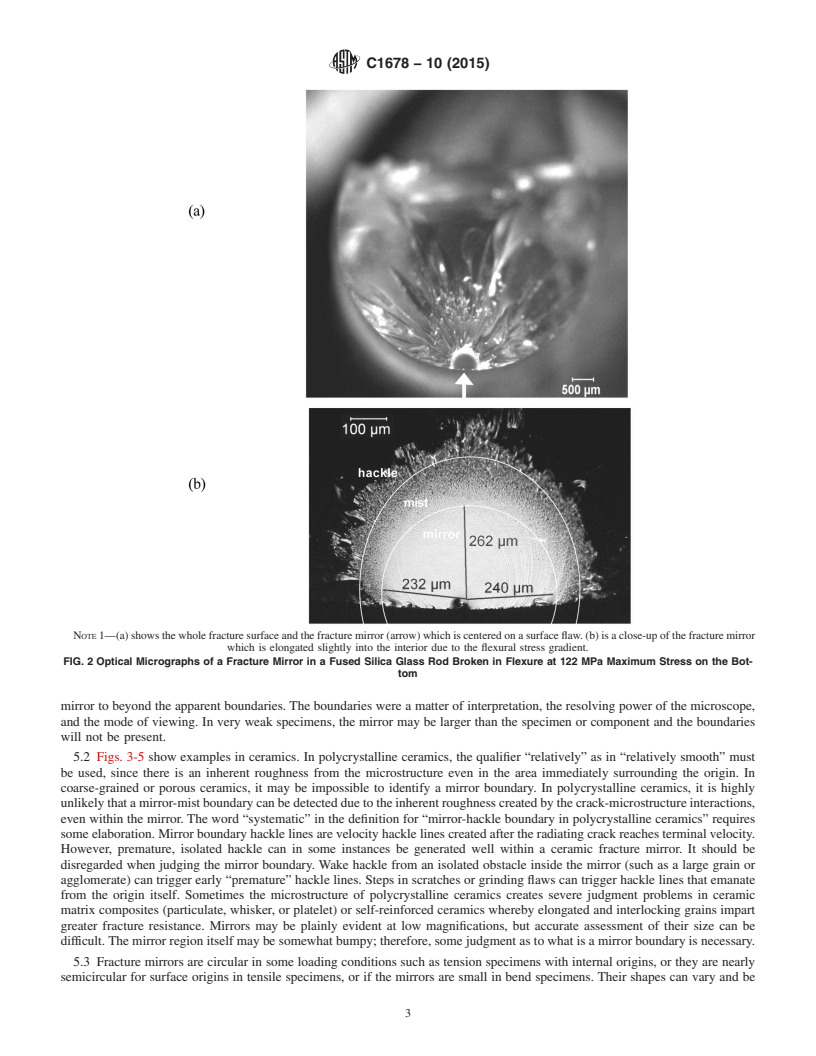
NOTE 1—(a) shows the whole fracture surface and the fracture mirror (arrow) which is centered on a surface flaw. (b) is a close-up of the fracture mirror
which is elongated slightly into the interior due to the flexural stress gradient.
FIG. 2 Optical Micrographs of a Fracture Mirror in a Fused Silica Glass Rod Broken in Flexure at 122 MPa Maximum Stress on the Bot-
tom
mirror to beyond the apparent boundaries. The boundaries were a matter of interpretation, the resolving power of the microscope,
and the mode of viewing. In very weak specimens, the mirror may be larger than the specimen or component and the boundaries
will not be present.
5.2 Figs. 3-5 show examples in ceramics. In polycrystalline ceramics, the qualifier “relatively” as in “relatively smooth” must
be used, since there is an inherent roughness from the microstructure even in the area immediately surrounding the origin. In
coarse-grained or porous ceramics, it may be impossible to identify a mirror boundary. In polycrystalline ceramics, it is highly
unlikely that a mirror-mist boundary can be detected due to the inherent roughness created by the crack-microstructure interactions,
even within the mirror. The word “systematic” in the definition for “mirror-hackle boundary in polycrystalline ceramics” requires
some elaboration. Mirror boundary hackle lines are velocity hackle lines created after the radiating crack reaches terminal velocity.
However, premature, isolated hackle can in some instances be generated well within a ceramic fracture mirror. It should be
disregarded when judging the mirror boundary. Wake hackle from an isolated obstacle inside the mirror (such as a large grain or
agglomerate) can trigger early “premature” hackle lines. Steps in scratches or grinding flaws can trigger hackle lines that emanate
from the origin itself. Sometimes the microstructure of polycrystalline ceramics creates severe judgment problems in ceramic
matrix composites (particulate, whisker, or platelet) or self-reinforced ceramics whereby elongated and interlocking grains impart
greater fracture resistance. Mirrors may be plainly evident at low magnifications, but accurate assessment of their size can be
difficult. The mirror region itself may be somewhat bumpy; therefore, some judgment as to what is a mirror boundary is necessary.
5.3 Fracture mirrors are circular in some loading conditions such as tension specimens with internal origins, or they are nearly
semicircular for surface origins in tensile specimens, or if the mirrors are small in bend specimens. Their shapes can vary and be
C1678 − 10 (2015)
NOTE 1—Notice how clear the mirror is in the low power images in (a) and (b). The mirror boundary (arrows in c) is where systematic new hackle
forms and there is an obvious roughness difference compared to the roughness inside the mirror region.
FIG. 3 Silicon Carbide Tension Strength Specimen (371 MPa) with a Mirror Centered on a Compositional Inhomogeneity Flaw
C1678 − 10 (2015)
NOTE 1— The mirror boundary is difficult to delineate in this material. (a) shows the uncoated fracture surface of a 2.8 mm thick flexural strength
specimen that fractured at 486 MPa. Vicinal illumination brings out the markings. (b) shows a mirror-hackle boundary where systematic new hackle is
detected (small white arrows) as compared to the roughness inside the mirror. The marked circle is elongated somewhat into the depth due to the stress
gradient. The radius in the direction along the bottom surface (a region of constant stress) was 345 mm.
FIG. 4 A Fracture Mirror in a Fine-Grained 3 Mol % Yttria-Stabilized Tetragonal Zirconia Polycrystal (3Y-TZP)
elongated or even incomplete in some directions if the fracture mirrors are in stress gradients. Fracture mirrors may be quarter
circles if they form from corner origins in a specimen or component. Fracture mirrors only form in moderate to high local stress
conditions. Weak specimens may not exhibit full or even partial mirror boundaries, since the crack may not achieve sufficient
velocity within the confines of the specimen.
C1678 − 10 (2015)
NOTE 1—The mirror is incomplete into the bend stress gradient, but the mirror sides can be used to construct boundary arcs in (c) [(b) and (c) are
close-ups of (a)]. Radii are measured in the direction of constant stress along the bottom.
FIG. 5 Silicon Nitride Bend Bar with a Knoop Surface Crack in a Silicon Nitride (449 MPa)
5.4 Fracture mirrors not only bring one’s attention to an origin, but also give information about the magnitude of the stress at
the origin that caused fracture and their distribution. The fracture mirror size and the stress at fracture are empirically correlated
by Eq 1:
σ=R 5 A (1)
where:
σ = stress at the origin (MPa or ksi),
R = fracture mirror radius (m or in),
A = fracture mirror constant (MPa√m or ksi√in).
Eq 1 is hereafter referred to as the “empirical stress – fracture mirror size relationship,” or “stress-mirror size relationship” for
short. A review of the history of Eq 1, and fracture mirror analysis in general, may be found in Refs 1 and 2.
C1678 − 10 (2015)
5.5 A, the “fracture mirror constant” (sometimes also known as the “mirror constant”) has units of stress intensity (MPa√m or
ksi√in) and is considered by many to be a material property. As shown in Figs. 1 and 2, it is possible to discern separate mist and
hackle regions and the apparent boundaries between them in glasses. Each has a corresponding mirror constant, A. The most
common notation is to refer to the mirror-mist boundary as the inner mirror boundary, and its mirror constant is designated A . The
i
mist-hackle boundary is referred to as the outer mirror boundary, and its mirror constant is designated A . The mirror-mist
o
boundary is usually not perceivable in polycrystalline ceramics. Usually, only the mirror-hackle boundary is measured and only
an A for the mirror-hackle boundary is calculated. A more fundamental relationship than Eq 1 may be based on the stress intensity
o
factors (K ) at the mirror-mist or mist-hackle boundaries, but Eq 1 is more practical and simpler to use.
I
5.6 The size predictions based on Eq 1 and the A values, or alternatively stress intensity factors, match very closely for the
limiting cases of small mirrors in tension specimens. This is also true for small semicircular mirrors centered on surface flaws in
strong flexure specimens. So, at least for some special mirror cases, A should be directly related to a more fundamental parameter
based on stress intensity factors.
5.7 The size of the fracture mirrors in laboratory test specimen fractures may be used in conjunction with known fracture mirror
constants to verify the stress at fracture was as expected
...
Questions, Comments and Discussion
Ask us and Technical Secretary will try to provide an answer. You can facilitate discussion about the standard in here.