

prEN 3475-808
(Main)Aerospace series - Cables, electrical, aircraft use - Test methods - Part 808: Cross-talk
General Information
- Abstract
This document specifies a method for measuring the cross-talk of a cable or between cables.
- Status
- Not Published
- Publication Date
- 01-Jan-2025
- Technical Committee
- ASD-STAN - Aerospace
- Drafting Committee
- ASD-STAN/D 2/S 2 - Cables & Stripping Tools
- Current Stage
- 4020 - Submission to enquiry - Enquiry
- Start Date
- 13-Aug-2026
- Due Date
- 04-Jul-2023
- Completion Date
- 13-Aug-2026

Overview
prEN 3475-808:2026 is a European draft standard developed by CEN within the Aerospace series for electrical cables used in aircraft. This document specifies a method for measuring cross-talk - the unwanted coupling of signals between adjacent cables or conductors - which is critical to ensuring the reliable operation of aircraft electrical systems. Cross-talk measurement is a key test in cable qualification and verification, supporting safety, electromagnetic compatibility, and performance requirements in aerospace applications.
This standard supersedes EN 3475-808:2002 and introduces updated procedures, such as the use of vector network analysers (VNAs), and supports both balun-based and balun-less measurement configurations to reflect current best practices for a variety of cable types and frequencies.
Key Topics
Scope of Cross-talk Measurement
- Methods for assessing cross-talk within a single cable or between multiple cables
- Applicability to both symmetrical (balanced) cables and coaxial cables used in aerospace environments
Test Methods
- Procedures based on IEC 61196-1-122:2006 and IEC 61156-1/-1-2:2023 for standardized testing
- Balun-based measurements for balanced cables, including requirements for calibration and termination
- Balun-less (mixed-mode) measurements, preferred at frequencies above 1000 MHz
- Detailed set-up for near-end (NEXT) and far-end cross-talk (FEXT) measurements, including required equipment and configuration of cable terminations
Expression of Results
- Calculation of near-end cross-talk attenuation (NEXT)
- Calculation of far-end cross-talk attenuation (FEXT)
- Use of power sum cross-talk for cables with multiple pairs
- Compliance requirements based on limits specified in the relevant product standard
Significant Updates
- Adoption of VNAs for increased measurement accuracy
- Enhanced procedures for higher frequency testing
- Updated guidance for appropriate terminations and calibration processes
Applications
prEN 3475-808:2026 is essential for:
Aerospace Manufacturers
- Qualification and acceptance testing of electrical cables for aircraft use
- Ensuring compliance with aerospace electrical system requirements
Cable Manufacturers
- Developing and producing low cross-talk cables for use in commercial and military aircraft
- Validating cable performance to meet stringent EMC and safety standards
Testing Laboratories
- Performing standardized cross-talk tests as part of certification, quality assurance, or research and development activities
System Integrators and Maintenance Providers
- Assessing cable integrity and continued performance in service
- Diagnosing electromagnetic interference issues within aircraft wiring systems
Cross-talk testing ensures that data, control, and power systems function without interference, enhancing the reliability and safety of avionics and electrical networks.
Related Standards
The following standards are referenced or related to prEN 3475-808:2026:
- EN 50289-1-1:2017: Communication cables - Specifications for test methods - Part 1-1: Electrical test methods - General requirements
- IEC 61196-1-122:2006: Coaxial communication cables - Electrical test methods - Test for cross-talk between coaxial cables
- EN 3475-100: Aerospace series - Cables, electrical, aircraft use - Part 100: General test methods
- IEC 61156-1 & 61156-1-2: Multicore and symmetrical pair/quad cables for digital communications - Transmission characteristics and test methods
These references ensure harmonization, reliability, and interoperability of cable testing methods within the aerospace sector.
Keywords: cross-talk measurement, aerospace cables, aircraft use, electrical cable testing, vector network analyser, balanced cable, coaxial cable, near-end cross-talk, far-end cross-talk, EMC, CEN standard, prEN 3475-808, aviation cable test methods
Relations
- Effective Date
- 19-Jan-2023
Get Certified
Connect with accredited certification bodies for this standard

BUREAU VERITAS Certification Germany
Bureau Veritas certification in Germany.

Element Materials Technology
Materials testing and product certification.

AQMS Ltd.
AQMS provides ISO certification to SMEs across the UK.
Sponsored listings
Frequently Asked Questions
prEN 3475-808 is a draft published by the European Committee for Standardization (CEN). Its full title is "Aerospace series - Cables, electrical, aircraft use - Test methods - Part 808: Cross-talk". This standard covers: This document specifies a method for measuring the cross-talk of a cable or between cables.
This document specifies a method for measuring the cross-talk of a cable or between cables.
prEN 3475-808 is classified under the following ICS (International Classification for Standards) categories: 49.060 - Aerospace electric equipment and systems. The ICS classification helps identify the subject area and facilitates finding related standards.
prEN 3475-808 has the following relationships with other standards: It is inter standard links to EN 3475-808:2002. Understanding these relationships helps ensure you are using the most current and applicable version of the standard.
prEN 3475-808 is available in PDF format for immediate download after purchase. The document can be added to your cart and obtained through the secure checkout process. Digital delivery ensures instant access to the complete standard document.
Standards Content (Sample)
SLOVENSKI STANDARD
01-oktober-2026
Nadomešča:
SIST EN 3475-808:2004
Aeronavtika - Električni kabli za uporabo v zračnih plovilih - Preskusne metode -
808. del: Presluh
Aerospace series - Cables, electrical, aircraft use - Test methods - Part 808: Cross-talk
Luft- und Raumfahrt – Elektrische Leitungen für Luftfahrt-Verwendung – Prüfverfahren–
Teil808: Nebensprechen
Série aérospatiale - Câbles électriques à usage aéronautique - Méthodes d'essais -
Partie 808 : Diaphonie
Ta slovenski standard je istoveten z: prEN 3475-808
ICS:
49.060 Letalska in vesoljska Aerospace electric
električna oprema in sistemi equipment and systems
2003-01.Slovenski inštitut za standardizacijo. Razmnoževanje celote ali delov tega standarda ni dovoljeno.
DRAFT
EUROPEAN STANDARD
NORME EUROPÉENNE
EUROPÄISCHE NORM
August 2026
ICS 49.060 Will supersede EN 3475-808:2002
English Version
Aerospace series - Cables, electrical, aircraft use - Test
methods - Part 808: Cross-talk
Série aérospatiale - Câbles électriques à usage Luft- und Raumfahrt - Elektrische Leitungen für
aéronautique - Méthodes d'essais - Partie 808 : Luftfahrt-Verwendung - Prüfverfahren- Teil808:
Diaphonie Nebensprechen
This draft European Standard is submitted to CEN members for enquiry. It has been drawn up by the Technical Committee ASD-
STAN.
If this draft becomes a European Standard, CEN members are bound to comply with the CEN/CENELEC Internal Regulations
which stipulate the conditions for giving this European Standard the status of a national standard without any alteration.
This draft European Standard was established by CEN in three official versions (English, French, German). A version in any other
language made by translation under the responsibility of a CEN member into its own language and notified to the CEN-CENELEC
Management Centre has the same status as the official versions.
CEN members are the national standards bodies of Austria, Belgium, Bulgaria, Croatia, Cyprus, Czech Republic, Denmark, Estonia,
Finland, France, Germany, Greece, Hungary, Iceland, Ireland, Italy, Latvia, Lithuania, Luxembourg, Malta, Netherlands, Norway,
Poland, Portugal, Republic of North Macedonia, Romania, Serbia, Slovakia, Slovenia, Spain, Sweden, Switzerland, Türkiye and
United Kingdom.
Recipients of this draft are invited to submit, with their comments, notification of any relevant patent rights of which they are
aware and to provide supporting documentation.
Warning : This document is not a European Standard. It is distributed for review and comments. It is subject to change without
notice and shall not be referred to as a European Standard.
EUROPEAN COMMITTEE FOR STANDARDIZATION
COMITÉ EUROPÉEN DE NORMALISATION
EUROPÄISCHES KOMITEE FÜR NORMUNG
CEN-CENELEC Management Centre: Rue de la Science 23, B-1040 Brussels
© 2026 CEN All rights of exploitation in any form and by any means reserved Ref. No. prEN 3475-808:2026 E
worldwide for CEN national Members.
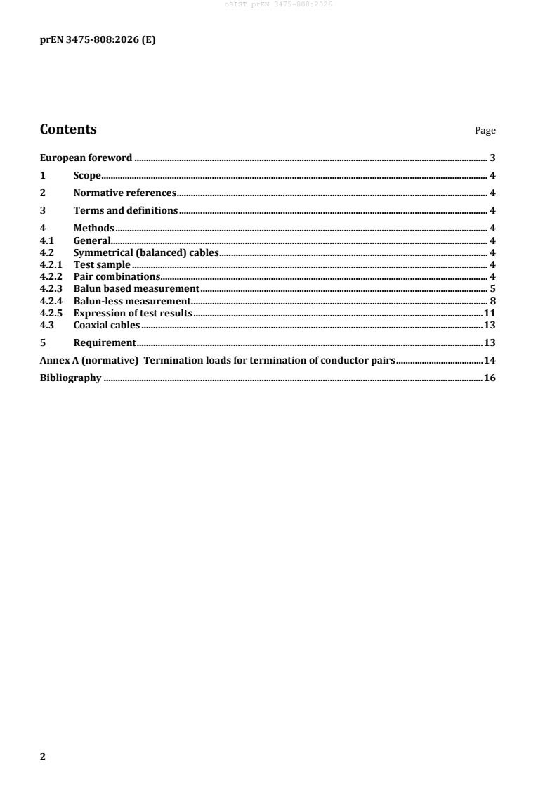
Contents Page
European foreword . 3
1 Scope . 4
2 Normative references . 4
3 Terms and definitions . 4
4 Methods . 4
4.1 General. 4
4.2 Symmetrical (balanced) cables . 4
4.2.1 Test sample . 4
4.2.2 Pair combinations. 4
4.2.3 Balun based measurement . 5
4.2.4 Balun-less measurement . 8
4.2.5 Expression of test results . 11
4.3 Coaxial cables . 13
5 Requirement . 13
Annex A (normative) Termination loads for termination of conductor pairs . 14
Bibliography . 16
European foreword
This document (prEN 3475-808:2026) has been prepared by ASD-STAN.
After enquiries and votes carried out in accordance with the rules of this Association, this document has
received the approval of the National Associations and the Official Services of the member countries of
ASD-STAN, prior to its presentation to CEN.
This document is currently submitted to the CEN Enquiry.
This document will supersede EN 3475-808:2002.
EN 3475-808:2002:
— the use of vector network analysers has been introduced to replace outdated test configurations
using a generator and an oscilloscope. The different cross-talk configurations are described in
detail. Balun less measurement configurations are introduced.
1 Scope
This document specifies a method for measuring the cross-talk of a cable or between cables.
2 Normative references
The following documents are referred to in the text in such a way that some or all of their content
constitutes requirements of this document. For dated references, only the edition cited applies. For
undated references, the latest edition of the referenced document (including any amendments) applies.
EN 50289-1-1:2017, Communication cables — Specifications for test methods — Part 1-1: Electrical test
methods — General requirements
IEC 61196-1-122:2006, Coaxial communication cables — Part 1-122: Electrical test methods — Test for
cross-talk between coaxial cables
3 Terms and definitions
No terms and definitions are listed in this document.
ISO and IEC maintain terminology databases for use in standardization at the following addresses:
— ISO Online browsing platform: available at https://www.iso.org/obp/
— IEC Electropedia: available at https://www.electropedia.org/
4 Methods
4.1 General
The test methods for the cross-talk between coaxial cables are based on IEC 61196-1-122:2006.
The test methods for the cross-talk of symmetrical (balanced) cables are based on IEC 61156-1:2023
and IEC 61156-1-2:2023.
4.2 Symmetrical (balanced) cables
4.2.1 Test sample
The cable under test (CUT) shall have a length of at least 25 m, if not stated otherwise. The maximum
cable length for the measurement of equal level far-end cross-talk (ACR-F) shall be such that the
measured far-end cross-talk attenuation (FEXT) is at least 10 dB less than the noise floor of the vector
network analyser (VNA), e.g. 80 db.
NOTE Equal level far-end cross-talk (ACR-F) was formerly denoted EL FEXT. The meaning of the acronym
ACR-F is attenuation to cross-talk ratio at far-end.
Both ends of the CUT shall be prepared, such that when connected to the terminals of the test
equipment the influence on the test result is minimized. The twisting of the pairs/quads shall be
maintained.
4.2.2 Pair combinations
In case of cables with more than two pairs (one quad) all pair combinations shall be measured. It is
admitted that measuring from pair A to pair B and pair B to pair A will essentially give the same results.
Therefore, in a cable with N pairs only N × (N-1) / 2 combinations may be measured. For example, in a
four pair cable, only six combinations may be measured: 1-2, 1-3, 1-4, 2-3, 2-4 and 3-4.
4.2.3 Balun based measurement
4.2.3.1 Test equipment
The test equipment shall be capable to measure the scattering parameters (as a complex quantity) of
the CUT in the frequency domain. A vector network analyser (VNA) having at least two ports and the
following is suitable:
— S-parameter set-up (shall be capable of performing measurements);
— baluns to convert the unbalanced signal of the VNA to a balanced signal. The baluns shall have an
impedance on the primary (unbalanced) side equal to the nominal impedance of the measuring
devices (in general 50 Ω) and on the secondary (balanced) side equal to the nominal impedance of
the cable under test (CUT) (e.g. 100 Ω). The baluns shall fulfil the requirements of Class A baluns as
described in EN 50289-1-1:2017;
— calibration artefacts to perform the required calibration of the test equipment on the secondary side
of the baluns. To perform a full two-port calibration a short circuit, an open circuit, a reference load,
and a short connection cable or similar, are required. The short circuit shall have negligible
inductance and the open circuit shall have negligible capacitance. The load resistor shall have a
value close (within 1 %) to the nominal impedance of the CUT (e.g. 100 Ω) and with negligible
inductance and capacitance. The connection cable shall be as short as possible and well matched to
the nominal impedance;
— resistor termination networks (RTN) for termination of inactive pairs. The resistor termination
network shall provide the differential mode and the common mode reference termination
impedances. For cables having a nominal (differential) impedance (Z ) of 100, the common-mode
diff
impedance (Z ) is:
com
• about 75 Ω for up to twenty-5 pair-count unscreened pair cables;
• about 50 Ω for common screened pair cables and more than twenty-5 pair-count unscreened
pair cables;
• about 25 Ω for individually screened pair cables.
In principle in balun measurements, the test shall be carried out with the condition that differential
mode impedance (Z ) and common mode impedance (Z ) of test specimen is matched by the balun
diff com
and the vector network analyser (or equivalent instruments) respectively.
But in practice, as the vector network analyser (or equivalent instrument) used in the measurement has
50 Ω ports in general and the common mode impedance of the balun is also 50 Ω, the common mode
impedance of the test specimen shall be assumed 50 Ω unless otherwise specified. This is to simplify
measurements when the common mode impedance of test specimen vary from 25 Ω to 75 Ω,
see Figure 1. Baluns may be used for termination of the inactive pairs if they provide the specified
differential and common mode terminations.
Key
Z is differential-mode termination resistor (Ω);
dm
Z is common-mode termination resistor (Ω);
cm
Z is differential-mode impedance of cable (Ω);
diff
Z is common-mode impedance of cable (Ω).
com
Figure 1 — Resistor terminations in balun measurements
4.2.3.2 Calibration procedure
It is not the intent of the standard to detail the algorithms applied by a VNA to correct the measured
results based on a calibration procedure, but to detail the calibration procedure. Further information
can be obtained in the manuals of the VNA supplier.
The calibration shall be performed on the secondary side of the baluns. A full two-port calibration is
recommended using open, short, and load calibration artefacts at the terminals of the balun, and a short
connection cable between the two baluns for the through calibration.
4.2.3.3 Measurement procedure for near-end cross-talk
The cable under test (CUT) shall be connected to the terminals of the test equipment as depicted in
Figure 2, including proper termination of the active pairs, the inactive pairs, and the screen.
The connection of the CUT to the test ports shall be optimized, such that the mismatch at the connection
is minimized.
One end of the pairs under test shall be connected to baluns, the other end shall be connected to ground
through appropriate common-mode and differential-mode terminations (see 4.2.3.1).
All pairs not under test shall be connected to ground through appropriate common-mode and
differential-mode terminations at the near and far end (see 4.2.3.1).
The screens, if any, shall be connected to ground at both ends of the cable. Precautions shall be taken to
minimize end effect couplings. When the cable sheath is removed, the pairs shall maintain their twist
and shall be well separated.
Measure the forward transmission scattering parameter differential mode, S .
dd21
Key
CUT cable under test
VNA/G network analyser port or generator
VNA/R network analyser port or receiver
* common-mode termination resistor
** differential-mode termination resistor (matched in pairs)
L length of cable under test (m)
Figure 2 — Balun based test set-up for near-end cross-talk
4.2.3.4 Measurement pr
...