

EN IEC 60068-2-64:2026
(Main)Environmental testing - Part 2-64: Tests - Test Fh: Vibration, broadband random and guidance
- Abstract
IEC 60068-2-64:2026 demonstrates the adequacy of a specimen to resist dynamic loads without unacceptable degradation of its functional and structural integrity (or either of them) when subjected to the specified random vibration test requirements. Broadband random vibration can be used to identify accumulated stress effects and the resulting mechanical weakness and degradation in the specified performance. This information, in conjunction with the relevant specification, can be used to assess the acceptability of specimens. This third edition cancels and replaces the second edition, published in 2008, and Amendment 1:2019. This edition constitutes a technical revision. This edition includes the following significant technical changes with respect to the previous edition: a) update of Annex A with references to examples; b) introduction of an organizational deviation treatment; c) clarification on requirements.
- Status
- Not Published
- Publication Date
- 19-Nov-2026
- Technical Committee
- CLC/SR 104 - Environmental conditions, classification and methods of test
- Current Stage
- 5060 - Voting results sent to TC, SR - Formal Approval
- Start Date
- 31-Jul-2026
- Completion Date
- 31-Jul-2026


EN IEC 60068-2-64:2026 is the European standard published by CLC for environmental testing of electrotechnical specimens under broadband random vibration. It specifies how to run Test Fh to show whether a specimen can withstand stochastic dynamic loads without unacceptable loss of functional or structural integrity, and it is written for test specifiers, manufacturers, purchasers, and test laboratories.
What does EN IEC 60068-2-64:2026 specify?
EN IEC 60068-2-64:2026 covers broadband random vibration testing for specimens exposed to transportation or operational vibration environments such as aircraft, space vehicles, and land vehicles. The standard is primarily intended for unpackaged specimens, but it also covers items in their transportation container when that container is part of the specimen.
The document is organized into clauses 1 to 12, followed by four informative annexes. It sets out scope, references, terms, apparatus requirements, severities, preconditioning, measurements, testing, recovery, and the information that must appear in the relevant specification and the test report.
| Annex | What it covers |
|---|---|
| Annex A | Guidance on test severities for transportation, stationary installations, storage, handling, portable use, wheeled vehicles, ships, and aircraft |
| Annex B | Guidance on good test quality and reproducibility |
| Annex C | Guidance on non-Gaussian distribution and high kurtosis tests |
| Annex D | Verification against the environmental test specification and test purpose |
What are the key requirements of EN IEC 60068-2-64:2026?
EN IEC 60068-2-64:2026 requires the test to be set up as a controlled vibration sequence with defined apparatus, control strategy, severities, measurements, and reporting. In practice, the document tells the laboratory how to generate the random vibration, how to check that the applied vibration matches the specification, and what information must be documented if the test deviates from plan.
Test apparatus and motion
Clause 4 requires the complete vibration system - power amplifier, vibrator, fixture, specimen, and control system - to meet the test needs when loaded. The basic motion at the fixing points shall be prescribed by the relevant specification, and the fixing points should move substantially together in phase and amplitude. If that is not achievable, the standard calls for multipoint control and monitoring of the differences.
For practical testing, this means fixture design and control channel placement matter as much as the shaker itself. Clause 4.3 also requires cross-axis motion to be checked, either before the test or during it, and any excess cross-axis motion must be reported or justified in relation to the test purpose.
Mounting and measuring systems
Clause 4.4 requires mounting according to IEC 60068-2-47 unless the relevant specification says otherwise. If a specimen is normally used with a vibration isolator and is tested without it, the applied acceleration spectral density (ASD) shall be corrected using the transfer function approach referenced from IEC 60068-2-6.
Clause 4.5 sets the measuring-system performance needed to judge whether the true motion at the reference point stays within tolerance. The effective frequency range of the measuring system shall extend from at least 0.5 times the lowest test frequency to 2.0 times the highest test frequency, and the response within the test band shall be flat within the stated tolerance. This is important because poor sensor or controller bandwidth can distort the result even if the shaker is working correctly.
Vibration tolerances and waveform shape
Clause 4.6 requires the indicated ASD at the reference point to stay within ±3 dB of the specified ASD, allowing for instrument and random error, and the RMS value of acceleration to stay within 10 % of the specified value. The initial slope shall be at least +6 dB/octave and the final slope shall be -24 dB/octave or steeper.
Clause 4.6.2 also requires the conventional random test to have an approximately Gaussian distribution, a drive-signal crest factor of at least 2.5, and peaks at the reference point of at least 3 times the specified RMS value unless otherwise specified. For non-Gaussian testing, the time history shall be recorded and characterized by crest factor, skewness, kurtosis, and amplitude probability distribution.
Statistical accuracy and frequency resolution
Clause 4.6.3 ties statistical accuracy to the statistical degrees of freedom (DOF), and the document requires at least 120 DOF unless otherwise specified. Clause 4.6.4 sets the frequency resolution, with a minimum of 2.5 Hz unless the relevant specification states otherwise.
In practice, these requirements influence how long the controller must average, how fine the spectral lines must be, and how confidently the lab can claim that the measured spectrum represents the true input. For resonance work, the clause also notes that a finer resolution may be needed to resolve narrow peaks properly.
Control strategy and testing sequence
Clause 4.7 allows single-point control, multipoint control, and multireference control. For multipoint control, the relevant specification shall state whether the control is based on averaging, weighted averaging, or extremal values, and the method used shall be stated in the report.
Clause 8 defines the usual sequence: initial vibration response investigation if required, low-level equalization, random vibration testing, and final response investigation if required. The specimen is tested in the preferred axes unless the relevant specification says otherwise, and interruptions, rest periods, and any recovery conditions must be handled and recorded as required.
Severities, deviations, and reporting
Clause 5 leaves the selection of test severities to the relevant specification, using the test frequency range, RMS acceleration, ASD shape, and test duration. For non-Gaussian tests, the severity also includes the distribution type, kurtosis or skewness where applicable, and the crest factor.
Clause 4.9 requires any deviation from the test specification or test method to be documented and quantified in the test report. Clauses 11 and 12 then define what the relevant specification and the report must state, including control point, measuring points, mounting, frequency resolution, control strategy, test duration, critical frequencies, and final acceptance or rejection criteria.
What terms does EN IEC 60068-2-64:2026 define?
- Cross-axis motion - motion not in the direction of the stimulus, usually in the two orthogonal axes; it matters because it can introduce unwanted loading on the specimen.
- Fixing point - the point where the specimen contacts the fixture or table in service; it matters because the control motion is defined around the real mounting interface.
- Reference point - the checkpoint used to control the test in single-point control; it matters because the control spectrum is compared there.
- Fictitious reference point - a control point derived from several checkpoints in multipoint control; it matters when one real point cannot represent the whole specimen.
- Acceleration spectral density (ASD) - the mean-square acceleration per unit bandwidth; it is the core quantity used to specify and control the random vibration.
- Crest factor - the ratio of peak value to RMS value of the time history; it matters because it affects waveform peaks and non-Gaussian capability.
- Statistical degrees of freedom (DOF) - an effective measure of averaging for random data analysis; it matters because it indicates statistical confidence in the measured ASD.
Who uses EN IEC 60068-2-64:2026?
EN IEC 60068-2-64:2026 is used by test laboratories, vibration test houses, design engineers, quality managers, purchasers, and test specifiers who need to define or verify random vibration tests. It is relevant to electrotechnical equipment, but the annexes also point to transportation, stationary installations, storage, portable use, wheeled vehicles, ships, and aircraft applications.
In practice, these users apply the standard to choose severities, define fixtures and checkpoints, compare pre- and post-test behaviour, and write specifications and reports that support acceptance decisions.
What changed in EN IEC 60068-2-64:2026 from the previous edition?
EN IEC 60068-2-64:2026 cancels and replaces the second edition published in 2008 and Amendment 1:2019. The scope and foreword state three technical changes: Annex A has been updated with references to examples, an organizational deviation treatment has been introduced, and the requirements have been clarified.
Which standards are used with EN IEC 60068-2-64:2026?
| Standard | What it contributes |
|---|---|
| IEC 60050-300 | General measurement and instrument vocabulary used for terms and definitions |
| IEC 60068-1 | General environmental testing guidance, including recovery conditions |
| IEC 60068-2-6 | Sinusoidal vibration testing and the isolator transfer function reference |
| IEC 60068-2-47 | Mounting of specimens for vibration and similar dynamic tests |
| IEC 60068-2-86 | Multi-exciter and multi-axis vibration testing |
| IEC 60068-3-8 | Guidance for selecting among vibration tests and interpreting vibration response investigations |
| IEC 60068-5-2 | Drafting terms and definitions for test methods |
What does the EN IEC 60068-2-64:2026 document contain?
The document contains the full test method for broadband random vibration, including apparatus requirements, severities, preconditioning, initial and final measurements, test execution, recovery, and reporting. It also includes figures for ASD tolerance bands, Gaussian and non-Gaussian time histories, and statistical accuracy versus degrees of freedom.
Annex A gives example environments and severity guidance for transport, stationary use, storage, portable use, vehicles, ships, and aircraft. Annex B focuses on reproducibility and control quality, Annex C explains non-Gaussian and high-kurtosis methods, and Annex D gives a structured way to verify that the test met its intended purpose.
Relations
- Effective Date
- 10-Nov-2026
- Effective Date
- 10-Nov-2026
- Effective Date
- 10-Nov-2026
- Effective Date
- 10-Nov-2026
- Effective Date
- 14-Jan-2025
- Effective Date
- 14-Jan-2025
Get Certified
Connect with accredited certification bodies for this standard

IMP NDT d.o.o.
Non-destructive testing services. Radiography, ultrasonic, magnetic particle, penetrant, visual inspection.

Inštitut za kovinske materiale in tehnologije
Institute of Metals and Technology. Materials testing, metallurgical analysis, NDT.

Q Techna d.o.o.
NDT and quality assurance specialist. 30+ years experience. NDT personnel certification per ISO 9712, nuclear and thermal power plant inspections, QA/
Sponsored listings
Frequently Asked Questions
EN IEC 60068-2-64:2026 is a draft published by CLC. Its full title is "Environmental testing - Part 2-64: Tests - Test Fh: Vibration, broadband random and guidance". This standard covers: IEC 60068-2-64:2026 demonstrates the adequacy of a specimen to resist dynamic loads without unacceptable degradation of its functional and structural integrity (or either of them) when subjected to the specified random vibration test requirements. Broadband random vibration can be used to identify accumulated stress effects and the resulting mechanical weakness and degradation in the specified performance. This information, in conjunction with the relevant specification, can be used to assess the acceptability of specimens. This third edition cancels and replaces the second edition, published in 2008, and Amendment 1:2019. This edition constitutes a technical revision. This edition includes the following significant technical changes with respect to the previous edition: a) update of Annex A with references to examples; b) introduction of an organizational deviation treatment; c) clarification on requirements.
IEC 60068-2-64:2026 demonstrates the adequacy of a specimen to resist dynamic loads without unacceptable degradation of its functional and structural integrity (or either of them) when subjected to the specified random vibration test requirements. Broadband random vibration can be used to identify accumulated stress effects and the resulting mechanical weakness and degradation in the specified performance. This information, in conjunction with the relevant specification, can be used to assess the acceptability of specimens. This third edition cancels and replaces the second edition, published in 2008, and Amendment 1:2019. This edition constitutes a technical revision. This edition includes the following significant technical changes with respect to the previous edition: a) update of Annex A with references to examples; b) introduction of an organizational deviation treatment; c) clarification on requirements.
EN IEC 60068-2-64:2026 is classified under the following ICS (International Classification for Standards) categories: 19.040 - Environmental testing. The ICS classification helps identify the subject area and facilitates finding related standards.
EN IEC 60068-2-64:2026 has the following relationships with other standards: It is inter standard links to EN 60068-5-2:1999, EN 60068-2-47:2005, EN 60068-2-6:2008, EN 60068-1:2014, EN 60068-2-64:2008, EN 60068-2-64:2008/A1:2019. Understanding these relationships helps ensure you are using the most current and applicable version of the standard.
EN IEC 60068-2-64:2026 is available in PDF format for immediate download after purchase. The document can be added to your cart and obtained through the secure checkout process. Digital delivery ensures instant access to the complete standard document.
Standards Content (Sample)
SLOVENSKI STANDARD
oSIST prEN IEC 60068-2-64:2026
01-februar-2026
Okoljski preskusi - 2-64. del: Preskusi - Preskus Fh: Vibracije, naključne
širokopasovne in vodilo
Environmental testing - Part 2-64: Tests - Test Fh: Vibration, broadband random and
guidance
Essais d'environnement - Partie 2-64: Essais - Essai Fh: Vibrations aléatoires à large
bande et guide
Ta slovenski standard je istoveten z: prEN IEC 60068-2-64:2025
ICS:
19.040 Preskušanje v zvezi z Environmental testing
okoljem
oSIST prEN IEC 60068-2-64:2026 en
2003-01.Slovenski inštitut za standardizacijo. Razmnoževanje celote ali delov tega standarda ni dovoljeno.
oSIST prEN IEC 60068-2-64:2026
oSIST prEN IEC 60068-2-64:2026
104/1136/CDV
COMMITTEE DRAFT FOR VOTE (CDV)
PROJECT NUMBER:
IEC 60068-2-64 ED3
DATE OF CIRCULATION: CLOSING DATE FOR VOTING:
2025-11-28 2026-02-20
SUPERSEDES DOCUMENTS:
104/1090/CD, 104/1119A/CC
IEC TC 104 : ENVIRONMENTAL CONDITIONS, CLASSIFICATION AND METHODS OF TEST
SECRETARIAT: SECRETARY:
Sweden Mr Joakim Grafström
OF INTEREST TO THE FOLLOWING COMMITTEES: HORIZONTAL FUNCTION(S):
TC 9,TC 17,SC 17C,TC 21,TC 23,SC 23E,TC 40,TC TC 104 Horizontal Basic Safety
45,SC 45B,TC 48,SC 48D,TC 49,TC 61,TC 62,SC
62A,TC 65,SC 65B,TC 82,TC 86,SC 86B,TC 94,TC 105
ASPECTS CONCERNED:
Safety
SUBMITTED FOR CENELEC PARALLEL VOTING NOT SUBMITTED FOR CENELEC PARALLEL VOTING
Attention IEC-CENELEC parallel voting
The attention of IEC National Committees, members of
CENELEC, is drawn to the fact that this Committee Draft
for Vote (CDV) is submitted for parallel voting.
The CENELEC members are invited to vote through the
CENELEC online voting system.
This document is still under study and subject to change. It should not be used for reference purposes.
Recipients of this document are invited to submit, with their comments, notification of any relevant patent rights of
which they are aware and to provide supporting documentation.
Recipients of this document are invited to submit, with their comments, notification of any relevant “In Some
Countries” clauses to be included should this proposal proceed. Recipients are reminded that the CDV stage is the
final stage for submitting ISC clauses. (SEE AC/22/2007 OR NEW GUIDANCE DOC).
TITLE:
Environmental testing - Part 2-64: Tests - Test Fh: Vibration, broadband random and guidance
PROPOSED STABILITY DATE: 2031
NOTE FROM TC/SC OFFICERS:
download this electronic file, to make a copy and to print out the content for the sole purpose of preparing National
Committee positions. You may not copy or "mirror" the file or printed version of the document, o r any part of it, for
any other purpose without permission in writing from IEC.0
oSIST prEN IEC 60068-2-64:2026
IEC CDV 60068-2-64 Ed.3 © IEC 2025
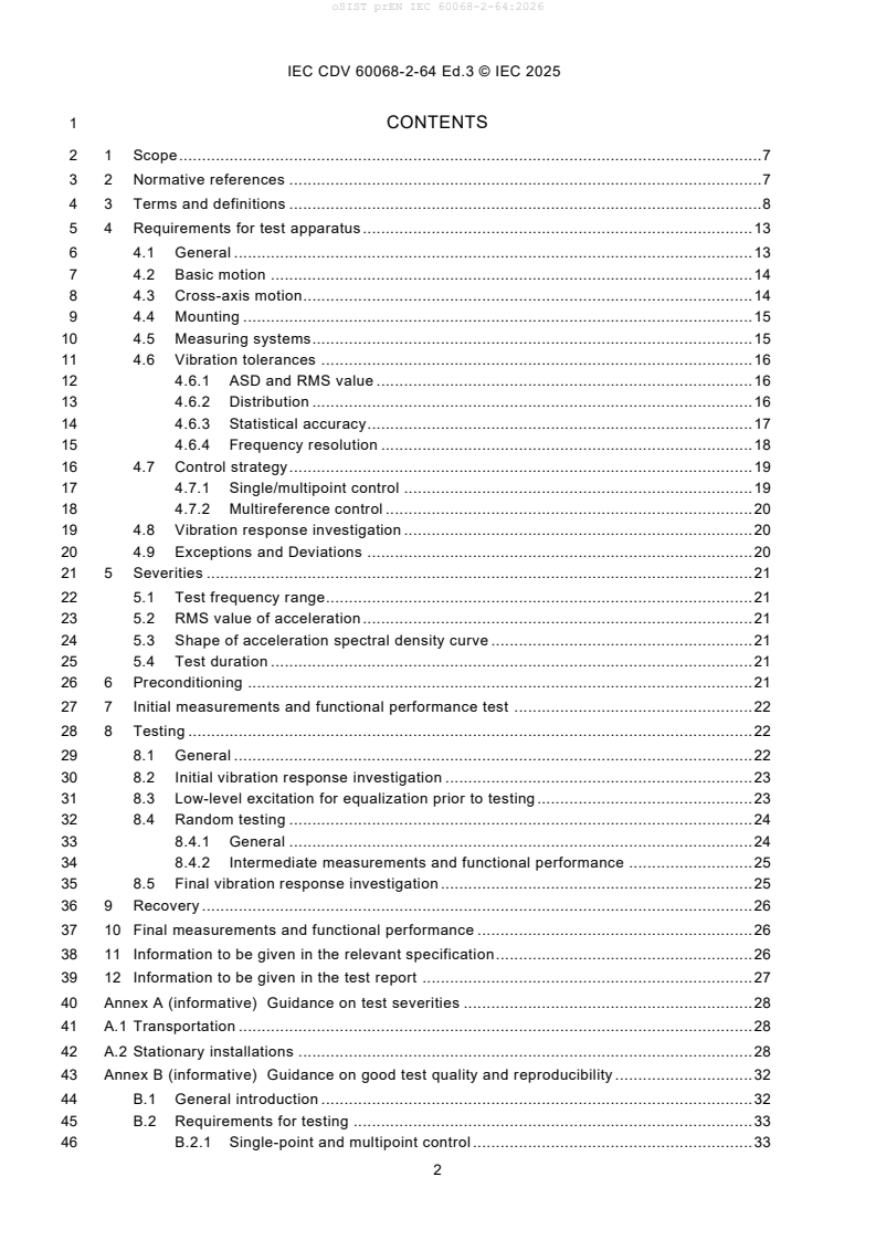
1 CONTENTS
2 1 Scope . 7
3 2 Normative references . 7
4 3 Terms and definitions . 8
5 4 Requirements for test apparatus . 13
6 4.1 General . 13
7 4.2 Basic motion . 14
8 4.3 Cross-axis motion. 14
9 4.4 Mounting . 15
10 4.5 Measuring systems . 15
11 4.6 Vibration tolerances . 16
12 4.6.1 ASD and RMS value . 16
13 4.6.2 Distribution . 16
14 4.6.3 Statistical accuracy . 17
15 4.6.4 Frequency resolution . 18
16 4.7 Control strategy . 19
17 4.7.1 Single/multipoint control . 19
18 4.7.2 Multireference control . 20
19 4.8 Vibration response investigation . 20
20 4.9 Exceptions and Deviations . 20
21 5 Severities . 21
22 5.1 Test frequency range. 21
23 5.2 RMS value of acceleration . 21
24 5.3 Shape of acceleration spectral density curve . 21
25 5.4 Test duration . 21
26 6 Preconditioning . 21
27 7 Initial measurements and functional performance test . 22
28 8 Testing . 22
29 8.1 General . 22
30 8.2 Initial vibration response investigation . 23
31 8.3 Low-level excitation for equalization prior to testing . 23
32 8.4 Random testing . 24
33 8.4.1 General . 24
34 8.4.2 Intermediate measurements and functional performance . 25
35 8.5 Final vibration response investigation . 25
36 9 Recovery . 26
37 10 Final measurements and functional performance . 26
38 11 Information to be given in the relevant specification. 26
39 12 Information to be given in the test report . 27
40 Annex A (informative) Guidance on test severities . 28
41 A.1 Transportation . 28
42 A.2 Stationary installations . 28
43 Annex B (informative) Guidance on good test quality and reproducibility . 32
44 B.1 General introduction . 32
45 B.2 Requirements for testing . 33
46 B.2.1 Single-point and multipoint control . 33
oSIST prEN IEC 60068-2-64:2026
IEC CDV 60068-2-64 Ed.3 © IEC 2025
47 B.2.2 Distribution . 33
48 B.2.3 Initial and final slope . 35
49 B.3 Testing procedures . 36
50 B.4 Equipment normally used with vibration isolators . 36
51 B.4.1 Transmissibility factors for isolators . 36
52 B.4.2 Temperature effect . 36
53 B.5 Test severities . 36
54 B.6 Equipment performance . 37
55 B.7 Initial and final measurements . 37
56 Annex C (informative) Guidance on non-Gaussian distribution/high kurtosis tests . 38
57 C.1 Non-Gaussian random vibration . 38
58 C.2 Methods to generate non-Gaussian random vibration . 38
59 C.2.1 General . 38
60 C.2.2 Amplitude modulation technique . 39
61 C.2.3 Phase modification technique . 39
62 C.2.4 Non-uniform phase technique . 40
63 C.3 Additional analysis . 40
64 C.4 Frequency range . 41
65 C.5 Beta distribution . 41
66 Annex D (informative) Verification against the environmental test specification and
67 test purpose . 42
68 D.1 Scope of test verification . 42
69 D.2 Purpose of test verification . 42
70 D.3 Information required for test verification . 43
71 D.4 Verification of test procedures and severities . 43
72 D.5 Verification of sequential test programme . 43
73 D.6 Technical verification of vibration tests . 44
75 Figure 1 – Tolerance bands for acceleration spectral density; initial and final slope
76 (see B.2.3) . 17
77 Figure 2 – Time history of stochastically excitation; probability density function with
78 Gaussian (normal) distribution (example with crest factor = 3, see also 3.16 and 4.6.2 ) . 18
79 Figure 3 – Statistical accuracy of acceleration spectral density versus degrees of
80 freedom for different confidence levels (see also 4.6.3) . 19
81 Figure 4 – Time history of non-Gaussian excitation – Probability density function
82 compared with Gaussian (normal) distribution . 26
oSIST prEN IEC 60068-2-64:2026
IEC CDV 60068-2-64 Ed.3 © IEC 2025
85 INTERNATIONAL ELECTROTECHNICAL COMMISSION
86 ____________
88 ENVIRONMENTAL TESTING –
90 Part 2-64: Tests – Test Fh: Vibration,
91 broadband random and guidance
94 FOREWORD
95 1) The International Electrotechnical Commission (IEC) is a worldwide organization for standardization comprising
96 all national electrotechnical committees (IEC National Committees). The object of IEC is to promote international
97 co-operation on all questions concerning standardization in the electrical and electronic fields. To this end and
98 in addition to other activities, IEC publishes International Standards, Technical Specifications, Technical Reports,
99 Publicly Available Specifications (PAS) and Guides (hereafter referred to as “IEC Publication(s)”). Their
100 preparation is entrusted to technical committees; any IEC National Committee interested in the subject dealt with
101 may participate in this preparatory work. International, governmental and non-governmental organizations liaising
102 with the IEC also participate in this preparation. IEC collaborates closely with the International Organization for
103 Standardization (ISO) in accordance with conditions determined by agreement between the two organizations.
104 2) The formal decisions or agreements of IEC on technical matters express, as nearly as possible, an international
105 consensus of opinion on the relevant subjects since each technical committee has representation from all
106 interested IEC National Committees.
107 3) IEC Publications have the form of recommendations for international use and are accepted by IEC National
108 Committees in that sense. While all reasonable efforts are made to ensure that the technical content of IEC
109 Publications is accurate, IEC cannot be held responsible for the way in which they are used or for any
110 misinterpretation by any end user.
111 4) In order to promote international uniformity, IEC National Committees undertake to apply IEC Publications
112 transparently to the maximum extent possible in their national and regional publications. Any divergence between
113 any IEC Publication and the corresponding national or regional publication shall be clearly indicated in the latter.
114 5) IEC provides no marking procedure to indicate its approval and cannot be rendered responsible for any equipment
115 declared to be in conformity with an IEC Publication.
116 6) All users should ensure that they have the latest edition of this publication.
117 7) No liability shall attach to IEC or its directors, employees, servants or agents including individual experts and
118 members of its technical committees and IEC National Committees for any personal injury, property damage or
119 other damage of any nature whatsoever, whether direct or indirect, or for costs (including legal fees) and
120 expenses arising out of the publication, use of, or reliance upon, this IEC Publication or any other IEC Publications.
121 8) Attention is drawn to the Normative references cited in this publication. Use of the referenced publications is
122 indispensable for the correct application of this publication.
123 9) Attention is drawn to the possibility that some of the elements of this IEC Publication may be the subject of patent
124 rights. IEC shall not be held responsible for identifying any or all such patent rights.
125 International Standard IEC 60068-2-64 has been prepared by IEC technical committee 104:
126 Environmental conditions, classification and methods of test.
127 This third edition cancels and replaces the second edition, published in 2008, and constitutes
128 a technical revision.
129 The major changes with regard to the previous edition concern the update of Annex A with
130 references to examples, the introduction of an organizational deviation treatment and some
131 clarification on requirements.
oSIST prEN IEC 60068-2-64:2026
IEC CDV 60068-2-64 Ed.3 © IEC 2025
133 The text of this document is based on the following documents:
FDIS Report on voting
134 Full information on the voting for the approval of this document can be found in the report on
135 voting indicated in the above table.
136 This publication has been drafted in accordance with the ISO/IEC Directives, Part 2.
137 A list of all the parts in the IEC 60068 series, under the general title Environmental testing, can
138 be found on the IEC website.
139 The committee has decided that the contents of this publication will remain unchanged until the
140 maintenance result date indicated on the IEC web site under "http://webstore.iec.ch" in the data
141 related to the specific publication. At this date, the publication will be
142 • reconfirmed,
143 • withdrawn,
144 • replaced by a revised edition, or
145 • amended.
oSIST prEN IEC 60068-2-64:2026
IEC CDV 60068-2-64 Ed.3 © IEC 2025
148 INTRODUCTION
149 This part of IEC 60068 deals with broadband random vibration testing intended for general
150 application to components, equipment and other products, hereinafter referred to as specimens,
151 that may be subjected to vibrations of a stochastic nature. The methods and techniques in this
152 document are based on digital control of random vibration. It permits the introduction of
153 variations to suit individual cases if these are prescribed by the relevant specification.
154 Compared with most other vibration tests, test Fh is not based on deterministic but on statistical
155 techniques. Broad-band random vibration testing is therefore described in terms of probability
156 and statistical averages.
157 It is emphasized that random testing always demands a certain degree of engineering
158 judgement, and both equipment supplier and purchaser as well as the test house should be
159 fully aware of this fact. The writer of the relevant specification is expected to select the testing
160 procedure and the values of severity appropriate to the specimen and its use.
161 The test method is based primarily on the use of an electrodynamic or a servo-hydraulic
162 vibration generator with an associated computer based control system relying on measurement
163 sensors used as a vibration testing system.
164 The traditional general purpose broad-band random vibration test utilizes waveforms with a
165 Gaussian distribution of amplitudes. However, when so specified, this test procedure can also
166 be utilized with random vibration tests with a non-Gaussian distribution of amplitudes. Such
167 tests are sometimes alternatively known as high kurtosis tests.
168 Annexes A and B are informative annexes giving reference to examples of test spectra for
169 different environmental conditions and a list of details to be considered for inclusion in
170 specifications and guidance.
171 Annex C is an informative annex giving information on non-Gaussian distribution/high kurtosis
172 tests.
173 Annex D is an informative annex giving guidance on technical measures of verification that the
174 intended test purpose is achieved by the test.
oSIST prEN IEC 60068-2-64:2026
IEC CDV 60068-2-64 Ed.3 © IEC 2025
176 ENVIRONMENTAL TESTING –
178 Part 2-64: Tests-Test Fh: Vibration,
179 broadband random and guidance
183 1 Scope
184 This part of IEC 60068 demonstrates the adequacy of specimens to resist dynamic loads
185 without unacceptable degradation of its functional and/or structural integrity when subjected to
186 the specified random vibration test requirements.
187 Broadband random vibration may be used to identify accumulated stress effects and the
188 resulting mechanical weakness and degradation in the specified performance. This information,
189 in conjunction with the relevant specification, may be used to assess the acceptability of
190 specimens.
191 This document is applicable to specimens which may be subjected to vibration of a stochastic
192 nature resulting from transportation or operational environments, for example, in aircraft, space
193 vehicles and land vehicles. It is primarily intended for unpackaged specimens, and for items in
194 their transportation container when the latter may be considered as part of the specimen itself.
195 However, if the item is packaged, then the item itself is referred to as a product and the item
196 and its packaging together are referred to as a test specimen. This document may be used in
197 conjunction with IEC 60068-2-47:2005, for testing packaged products.
198 If the specimens are subjected to vibration of a combination of random and deterministic nature
199 resulting from transportation or real life environments, for example, in aircraft, space vehicles
200 and for items in their transportation container, testing with pure random may not be sufficient.
201 See IEC 60068-3-8:2003 for estimating the dynamic vibration environment of the specimen and
202 based on that, selecting the appropriate test method.
203 Although primarily intended for electrotechnical specimens, this document is not restricted to
204 them and may be used in other fields where desired (see Annex A).
205 2 Normative references
206 The following documents are referred to in the text in such a way that some or all of their content
207 constitutes requirements of this document. For dated references, only the edition cited applies.
208 For undated references, the latest edition of the referenced document (including any
209 amendments) applies.
210 IEC 60050-300: International Electrotechnical Vocabulary – Electrical and electronic
211 measurements and measuring instruments
212 – Part 311: General terms relating to measurements
213 – Part 312: General terms relating to electrical measurements
214 – Part 313: Types of electrical measuring instruments
215 – Part 314: Specific terms according to the type of instrument
216 IEC 60068-1: Environmental testing – Part 1: General and guidance
oSIST prEN IEC 60068-2-64:2026
IEC CDV 60068-2-64 Ed.3 © IEC 2025
217 IEC 60068-2-6: Environmental testing – Part 2-6: Tests – Test Fc: Vibration (sinusoidal)
218 IEC 60068-2-47, Environmental testing – Part 2-47: Tests – Mounting of specimens for vibration,
219 impact and similar dynamic tests
220 IEC 60068-2-86: Environmental testing – Part 2-86: Tests -Test Fx: Vibration – Multi-exciter
221 and multi-axis method
222 IEC 60068-3-8: Environmental testing – Part 3-8: Supporting documentation and guidance –
223 Selecting amongst vibration tests
224 IEC 60068-5-2: Environmental testing – Part 5-2: Guide to drafting of test methods – Terms and
225 definitions
226 3 Terms and definitions
227 For the purposes of this document, the following terms and definitions apply.
228 ISO and IEC maintain terminological databases for use in standardization at the following
229 addresses:
230 – IEC Electropedia: available at http://www.electropedia.org/
231 – ISO Online browsing platform: available at http://www.iso.org/obp
232 NOTE 1 The terms used are generally defined in IEC 60050-300, IEC 60068-1, IEC 60068-2-6, and IEC 60068-5-2
233 and ISO 2041. If a definition from one of those sources is included here, the derivation is indicated and departures
234 from the definitions in those sources are also indicated.
235 3.1
236 cross-axis motion
237 motion not in the direction of the stimulus; generally specified in the two axes orthogonal to the
238 direction of the stimulus
239 Note 1 to entry: The cross-axis motion should be measured close to the fixing points.
240 3.2
241 actual motion
242 motion represented by the wideband signal returned from the reference point transducer
243 3.3
244 fixing point
245 part of the specimen in contact with the fixture or vibration table at a point where the specimen
246 is normally fastened in service
247 Note 1 to entry: If a part of the real mounting structure is used as the fixture, the fixing points are taken as those of
248 the mounting structure and not of the specimen.
249 Note 2 to entry: Where the specimen consists of a packaged product, fixing point can be interpreted as the surface
250 of the specimen which is in contact with the vibration table.
252 3.4
253 control methods
254 3.4.1
255 single point control
256 control method using the signal from the transducer at the reference point in order to maintain
257 this point at the specified vibration level
258 3.4.2
259 multipoint control
260 control method using the signals from each of the transducers at the checkpoints
oSIST prEN IEC 60068-2-64:2026
IEC CDV 60068-2-64 Ed.3 © IEC 2025
261 Note 1 to entry: The signals are either continuously averaged arithmetically or processed by using comparison
262 techniques, depending upon the relevant specification. See also 3.13.
263 3.5
264 g
n
265 standard acceleration due to the earth’s gravity, which itself varies with altitude and
266 geographical latitude
267 Note 1 to entry: For the purposes of this document, the value of g is rounded up to the nearest whole number, that
n
268 is 10 m/s .
269 3.6
270 measuring points
271 specific points at which data are gathered for conducting the test
272 Note 1 to entry: These points are of three types, as defined in 3.7 to 3.9.
273 3.7
274 checkpoint
275 point located on the fixture, on the vibration table or on the specimen as close as possible to
276 one of its fixing points, and in any case, rigidly connected to it
277 Note 1 to entry: A number of checkpoints are used as a means of ensuring that the test requirements are satisfied.
278 3.8
279 reference point,
280 point, chosen from amongst the checkpoints, whose signal is used to control the test, such that
281 the requirements of this standard are satisfied
282 3.9
283 fictitious reference point,
284 point, derived from multiple checkpoints either manually or automatically, the result of which is
285 used to control the test so that the requirements of this document are satisfied
286 3.10
287 response points
288 specific points on the specimen from which data is gathered for the purpose of the v ibration
289 response investigation
290 Note 1 to entry: These points are not the same as checkpoints or reference points.
291 3.11
292 preferred testing axes
293 three (usually) orthogonal axes that correspond to the most vulnerable axes of the specimen.
294 Note 1 to entry: The selection of the preferred testing axes can be depending on the specimen’s design and the
295 sub-components inside, may not always be orthogonal; the in-service mounting orientation of the specimen can also
296 play a role in the selection of the preferred testing axes. See also IEC 60068-2-86 for more information on multi-axis
297 testing.
298 3.12
299 Sampling frequency
300 number of discrete magnitude values taken per second to record or represent a time -history in
301 a digital form
302 3.13
303 multipoint control strategies
304 method for calculating the reference control signal when using multipoint control
305 Note 1 to entry: Different frequency domain control strategies are discussed to in 4.7.1.
oSIST prEN IEC 60068-2-64:2026
IEC CDV 60068-2-64 Ed.3 © IEC 2025
306 3.14
307 averaging
308 process of determining the control acceleration spectral density formed from the arithmetic
309 average of the acceleration spectral densities at each frequency line of more than one
310 checkpoint
311 3.15
312 extremal
313 process of determining the control acceleration spectral density formed from the maximum or
314 minimum acceleration spectral density at each frequency line of more than one checkpoint
315 3.16
316 crest factor
317 ratio of the peak value to the RMS value of the time history
318 3.17
319 –3 dB bandwidth
320 frequency bandwidth between two points in a frequency response function which are at 0,707
321 of the maximum response when associated with a single resonance peak. Can be applied to
322 power or field dimensions but chosen dimension is to be given
323 3.18
324 acceleration spectral density
325 ASD
326 mean-square value of that part of an acceleration signal passed by a narrow-band filter of a
327 centre frequency, per unit bandwidth, in the limit as the bandwidth approaches zero and the
328 averaging time approaches infinity
329 3.19
330 control acceleration spectral density
331 acceleration spectral density measured at the reference point or the fictitious reference point
332 3.20
333 control system loop
334 sum of the following actions:
335 – digitizing the analogue waveform of the signal derived from the reference point or
336 fictitious reference point;
337 – performing the necessary processing;
338 – producing an updated analogue drive waveform to the vibration system power amplifier
339 (see Clause B.1.)
340 Note 1 to entry: Subsystems in the control system loop and steps in the signal processing chain can be:
341 - Transducer (measurement instrument transferring the physical quantity to be measured – usually kinetic
342 like acceleration – to an electric signal), feeding to
343 - Signal conditioning – can be included in controller (power supply, AC-coupling) or the transducer (charge
344 amplifier), feeding to
345 - Controller (producing a defined output signal to achieve a certain wanted vibration environment), feeding
346 drive signal to
347 - Power amplifier (including further control loops and signal processing), feeding to
348 - Shaker (transfer from electric actuation power to mechanical movement and force), movement measurement
349 by transducer
oSIST prEN IEC 60068-2-64:2026
IEC CDV 60068-2-64 Ed.3 © IEC 2025
350 3.21
351 drive signal clipping
352 limitation of the maximum crest factor imposed on the drive signal within the effective frequency
353 range. It is process to apply the required crest factor (3.15) to the drive signal(s) produced by
354 the digital control system
355 3.22
356 effective frequency range
357 frequency range of measurement and control between 0,5 times f and 2,0 times f of the test
1 2
358 frequency range, (see also Figure 1)
359 Note 1 to entry: Due to initial and final slope, the effective frequency range is higher than the test frequency range
360 between f and f .
1 2
361 3.23
362 error acceleration spectral density
363 difference between the specified acceleration spectral density and the control acceleration
364 spectral density
365 3.24
366 equalization
367 minimization of the error acceleration spectral density
368 3.25
369 final slope
370 part of the specified acceleration spectral density above f , (see also Figure 1)
371 3.26
372 frequency resolution
373 B
e
374 width of the frequency intervals in the acceleration spectral density in Hertz
375 Note 1 to entry: It is equal to the reciprocal of the record block length (T) in digital analysis; the number of frequency
376 lines is equal to the number of intervals in a given frequency range
377 3.27
378 indicated acceleration spectral density
379 estimate of the true acceleration spectral density read from the analyser presentation distorted
380 by the instrument error and the random error
381 3.28
382 initial slope (see also Figure 1)
383 part of the specified acceleration spectral density below f
384 3.29
385 instrument error
386 error associated with each analogue item of the input to the control system and control system
387 analogue items
388 3.30
389 random error
390 error changing from one estimate to another of the acceleration spectral density because of the
391 limitation of averaging time and filter bandwidth in practice; with an infinite averaging time the
392 error would converge towards zero
393 3.31
394 record
395 collection of equally spaced data points in the time domain that are used in the calculation of
396 the Fast Fourier Transform
oSIST prEN IEC 60068-2-64:2026
IEC CDV 60068-2-64 Ed.3 © IEC 2025
397 3.32
398 reproducibility
399 closeness of the agreement between the results of measurements of the same value of the
400 same quantity, where the individual measurements are made
401 – by different methods,
402 – with different measuring instruments,
403 – with different signal generation,
404 – by different observers,
405 – in different laboratories,
406 – after intervals of time which are long compared with the duration of a single
407 measurement,
408 – under different customary conditions of use of the instruments employed
409 Note 1 to entry: The term “reproducible” also applies to the case where only certain of the preceding conditions are
410 taken into account.
411 3.33
412 root-mean-square value
413 root-mean-square value (RMS value) of a single-valued function over an interval between two
414 frequencies is the square root of the average of the squared values of all functions over the
415 total frequency interval f and f , (see also Figure 2)
1 2
416 3.34
417 standard deviation)
418
419 The RMS value of the deviation of a random time history from a mean value, (see also Figure
420 2
421 Note 1 to entry: In vibration theory, the mean value of vibration is equal to zero; therefore, for a random time history,
422 the standard deviation is equal to the RMS value. For non-gaussian distribution see Annex C.
423 3.35
424 statistical accuracy
425 ratio of true acceleration spectral density to indicated acceleration spectral density
426 3.36
427 statistical degrees of freedom
428 DOF
429 effective number derived from the frequency resolution and the effective averaging time for
430 estimation of acceleration spectral density of random data with a time-averaging technique,
431 (see also Figure 3)
432 3.37
433 test frequency range
434 frequency range between f and f (see Figure 1) in which the ASD is constant or shaped as
1 2
435 given in the relevant specification
436 3.38
437 true acceleration spectral density
438 acceleration spectral density of the random signal acting on the specimen
oSIST prEN IEC 60068-2-64:2026
IEC CDV 60068-2-64 Ed.3 © IEC 2025
439 3.39
440 kurtosis
th
441 4 statistical moment, which provides a measure of the shape of an amplitude distribution
442 Note 1 to entry: Typically, a waveform with Gaussian distribution will have a kurtosis of 3, if considered over an
443 infinite period.
444 Note 2 to entry: Kurtosis is given by:
N
kurtosis=− .xx
( )
i
N
i =1
446 where:
447 σ is the standard deviation of the N values which describe the waveform;
448 x are individual values representing the waveform described by N such values;
i
449 𝑥̅ is the mean value of the N values which describe the waveform.
450 3.40
451 skewness
rd
452 3 statistical moment, which provides a measure of non-symmetry of an amplitude distribution
453 NOTE 1 TO ENTRY: Typically, a waveform with Gaussian distribution will have a skewness of 0, if considered over
454 an infinite period.
455 NOTE 2 TO ENTRY: Skewness is given by:
N
skewness=− .xx
( )
i
N
i =1
457 where:
458 σ is the standard deviation of the N values which describe the waveform;
459 x are individual values representing the waveform described by N such values;
i
460 𝑥̅ is the mean value of the N values which describe the waveform.
461 4 Requirements for test apparatus
462 4.1 General
463 The required characteristics apply to the complete vibration system, which includes the power
464 amplifier, vibrator, test fixture, specimen and control system when loaded for testing.
465 The standardized test method consists of the following test sequence normally applied in each
466 of the mutually perpendicular axes of the test specimen:
467 1) An initial vibration response investigation, with low level sinusoidal excitation, or low level
468 random excitation, (see 8.2).
469 2) The random excitation as the mechanical load or stress test.
470 3) A final vibration response investigation to compare the results with the initial one and to
471 detect possible mechanical failures due to a change of the dynamic behaviour (see 8.2 and
472 8.5).
473 Where the dynamic behaviour is known, and it is not considered relevant, or sufficient data can
474 be gathered during the test at full level, the relevant specification may not require pre and post -
475 test vibration response investigations.
oSIST prEN IEC 60068-2-64:2026
IEC CDV 60068-2-64 Ed.3 © IEC 2025
476 For non-Gaussian testing, the test apparatus shall be able to produce a signal with a specified
477 probability distribution and crest factor. Generally, non-Gaussian random vibration testing
478 requires shaker and amplifier systems that are designed for Gaussian random vibrations but
479 with increased crest factor capabilities.
480 4.2 Basic motion
481 The basic motion of the fixing points of the specimen shall be prescribed by the relevant
482 specification and measured as actual motion. The fixing points should have substantially
483 identical motions in phase and amplitude (within the requirements set here and in the test
484 specification) and shall be rectilinear relative to the direction of excitation. If substantially
485 identical motions are difficult to achieve, then a multipoint control strategy shall be used.
486 Deviations between the excitation points shall be monitored and documented.
487 Definition and guidance on appropriate fixtures are found in IEC 60068-2-47 (Mounting). For
488 technical measures to verify that the test purpose is still fulfilled, see Annex D.
489 NOTE 1 For large structures and a high frequency range, for example, 20 Hz to 2 000 Hz, the dynamics of the test
490 specimen is likely to require multipoint control.
491 NOTE 2 If four or fewer fixing points exist, each is used as a checkpoint. For packaged products, where a fixing
492 point can be interpreted as the packaging surface in contact with the vibration table, one checkpoint can be used,
493 provided that there are no effects due to resonances of the vibration table or the mounting structure in the frequency
494 range specified for the test. If this is the case, multipoint control may be recommended, but see also NOTE 3. If more
495 than four fixing points exist, four representative fixing points will be defined in the relevant specification to be used
496 as checkpoints.
497 NOTE 3 In special cases, for example, for large or complex specimens, the checkpoints will be prescribed by the
498 relevant specification if not close to the fixing points.
499 NOTE 4 Where a large number of small specimens are mounted on one fixture, or in the case of a small specimen
500 with a number of fixing points, a single checkpoint (that is the reference point) can be selected for the derivation of
501 the control signal. This signal is then related to the fixture rather than to the fixing points of the specimen(s). This
502 procedure is only valid when the lowest resonance frequency of the loaded fixture is well above the upper frequency
503 of the test.
505 4.3 Cross-axis motion
506 Unless specified otherwise by the relevant specification cross-axis motion shall be checked,
507 either before the test is applied by conducting a sine or random investigation at a level
508 prescribed by the relevant specification, or during testing by utilising additional monitoring
509 channels in the two perpendicular axes.
510 If not specified otherwise, the following applies:
511 The ASD value of each frequency at the checkpoints in both axes perpendicular to the specified
512 axis shall not exceed the specified ASD values above 500 Hz and below 500 Hz shall not
513 exceed –3 dB of the specified ASD values. The total RMS value of acceleration in both axes
514 perpendicular to the specified axis shall not exceed 50 % of the RMS value for the specified
515 axis. For example, for a small specimen, the ASD value of the permissible cross axis motion
516 may be limited such that it does not exceed –3 dB of the basic motion, if so prescribed by the
517 relevant specification.
518 At some frequencies or with large-size or high-mass specimens, it may be difficult to achieve
519 these values. Also, in those cases where the relevant specification requires severities with a
520 large dynamic range, it may also be difficult to achieve these. In such cases, the relevant
521 specification shall state which of the following requirements applies:
522 a) any cross-axis motion in excess of that given above shall be stated in the test report;
523 b) cross-axis motion which is known to offer no hazard to the specimen and comply with the
524 test purpose need not be monitored (see Annex D).
oSIST prEN IEC 60068-2-64:2026
IEC CDV 60068-2-64 Ed.3 © IEC 2025
525 Often, the cross-axis motion is produced by torsion, when the mass centre and stiffness centre
526 are not at same point, usually resulting in a rotation. This may be important especially for large
527 specimen.
528 Exception clauses from sub-clause 4.9 apply accordingly for organizational measures in case
529 of exceptions and deviations. For technical measures to verify that the test purpose is still
530 fulfilled, see Annex D.
531 4.4 Mounting
532 Unless specified otherwise in the relevant specification, the test specimen shall be mounted in
533 accordance with IEC 60068-2-47.
534 However, when a test specimen that is normally used with a vibration isolator is tested without
535 the isolator, the vibration level should be adjusted accordingly.
536 In this case, and unless another method is specified in the relevant specification, the
537 appropriate transfer function curve shall be selected from IEC 60068-2-6, Figure A.1, and
538 multiply the specified ASD with the square of the value obtained from this curve to make the
539 correction.
540 4.5 Measuring systems
541 The characteristics of the measuring system shall be such that it can be determined whether
542 the true value of the vibration as measured in the intended axis at the reference point is within
543 the tolerance required for the test.
544 The frequency response of the overall measuring system, which includes the transducer, the
545 signal conditioner and the data acquisition with a chosen sampling frequency and processing
546 device, has a significant effect on the accuracy of the measurements. The effective frequency
547 range of the measuring system shall extend from at least 0,5 times the lowest frequency ( f ) to
548 2,0 times the highest frequency (f ) of the test frequency range (see Figure 1). The frequency
549 response of the measuring system shall be flat within 5 % of the test frequency range. Outside
550 of this range any further deviation shall be stated in the test report.
oSIST prEN IEC 60068-2-64:2026
IEC CDV 60068-2-64 Ed.3 © IEC 2025
+3 dB
–3 dB
Initial slope Final slope
normally –24 dB/octave
+6 dB/octave or steeper
or steeper
0,5f1 f1 f2 2f2
Frequency (Hz) (log. scale)
IEC 581/08
552 Figur
...