

IEC 60909-0:2026
(Main)Short-circuit currents in three-phase AC systems - Part 0: Calculation of currents
- Abstract
IEC 60909-0:2026 This part of IEC 60909 is applicable to the calculation of short-circuit currents in low-voltage three-phase AC systems, in high-voltage three-phase AC systems, and operating at a nominal frequency of 50 Hz or 60 Hz.
Systems at highest voltages of 550 kV and above with long transmission lines are outside the scope of this document.
- Status
- Published
- Publication Date
- 22-Jul-2026
- Technical Committee
- TC 73 - Short-circuit currents
- Drafting Committee
- MT 1 - TC 73/MT 1
- Current Stage
- PPUB - Publication issued
- Start Date
- 23-Jul-2026
- Completion Date
- 18-Aug-2026
Buy Documents
IEC 60909-0:2026 - Short-circuit currents in three-phase AC systems - Part 0: Calculation of currents
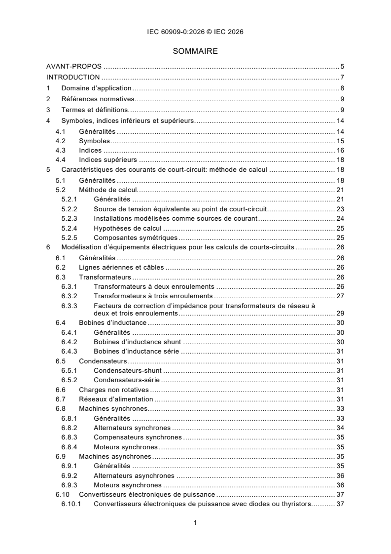
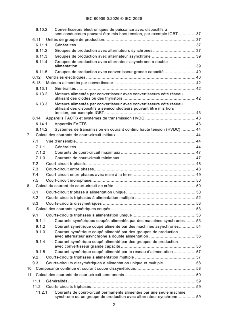
IEC 60909-0:2026 - Courants de court-circuit dans les réseaux triphasés a courant alternatif - Partie 0: Calcul des courants
IEC 60909-0:2026 is an International Standard published by IEC for calculating short-circuit currents in three-phase AC systems. It specifies a practical procedure for low-voltage and high-voltage networks at a nominal frequency of 50 Hz or 60 Hz, with results used for equipment ratings, protection settings, and related network studies.
What does IEC 60909-0:2026 specify?
IEC 60909-0:2026 specifies how to calculate short-circuit currents in low-voltage and high-voltage three-phase AC systems, including balanced and unbalanced faults. It uses an equivalent voltage source at the short-circuit location as the main calculation approach.
The document also states where it does not apply, and it organises the subject from general principles through equipment modelling and fault-current calculation methods to thermal checks.
| Annex | What it covers |
|---|---|
| Annex A | Short-circuit current inside a power station unit with synchronous generator |
| Annex B | Formulas for the calculation of the factors m and n |
The main body runs from Scope and normative references through terms, symbols, calculation methods, equipment models, initial current calculations, peak and breaking currents, steady-state currents, special transformer and motor cases, and thermal equivalent current and Joule integral.
What are the key requirements of IEC 60909-0:2026?
IEC 60909-0:2026 sets up a calculation framework that starts from the network topology and rated equipment data, then derives short-circuit currents for specific fault types. In practice, this means the user needs the system voltage, impedances, machine data, transformer data, and connection arrangement before a fault study can be completed.
Calculation method and fault levels
Clause 5 defines the main method and distinguishes far-from-generator and near-to-generator short circuits. The document focuses on maximum and minimum short-circuit currents, because maximum values are used for equipment rating and minimum values are used for fuse selection, protection settings, and motor run-up checks.
Clause 5 also says the equivalent voltage source method is the general procedure, while other special methods may be used if they give at least the same precision. That matters when a study uses a more detailed model or when an existing network is checked with measured data.
Equipment modelling
Clause 6 gives the modelling rules for overhead lines, cables, transformers, reactors, capacitors, non-rotating loads, feeders, synchronous machines, asynchronous machines, converters, power station units, power plants, converter-fed motors, FACTS devices, and HVDC transmission systems. A key practical rule is that positive-sequence and negative-sequence impedances are taken as equal for lines, cables, reactors, capacitors, and network feeders, while rotating machines can have different sequence impedances.
Clause 6 also requires impedance correction factors for synchronous generators, network transformers, and some power station units when calculating maximum short-circuit currents. In practice, this changes the impedance used in the study and therefore the resulting fault current.
Initial short-circuit currents
Clause 7 gives the calculation of initial short-circuit currents for three-phase, line-to-line, line-to-line with earth connection, and line-to-earth faults. Full-size converter contributions are included through source currents and nodal impedance terms, so the study must account for converter-connected installations separately from passive network elements.
Clause 7 also shows how the voltage factor c is applied, and how maximum and minimum cases are handled. That matters because the same network can produce different fault duties depending on operating voltage and the case being studied.
Peak current, breaking current, and DC component
Clause 8 gives the peak short-circuit current, using factor κ and the R/X ratio of the relevant branch or equivalent network. For multiple-fed faults, the standard gives several ways to determine the R/X ratio and recommends the equivalent frequency method.
Clause 9 covers symmetrical breaking currents, and Clause 10 covers the DC component and the unbalanced asymmetrical breaking current. This is important for switchgear duty, because the moment of contact separation and the decaying DC component both affect interruption stress.
Steady-state and thermal checks
Clause 11 gives steady-state short-circuit currents, which are less accurate than initial values but needed where the fault current after transients matters. Clause 14 then defines the thermal equivalent short-circuit current and the Joule integral, using factors m and n.
That thermal result is what users need when checking heating stress in conductors and equipment over the fault duration. For repeated faults, the document sums the individual Joule integrals.
What terms does IEC 60909-0:2026 define?
- short circuit - an accidental or intentional conductive path between two or more conductive parts that drives the voltage difference close to zero.
- prospective short-circuit current - the current that would flow if the fault were replaced by an ideal connection with negligible impedance.
- initial symmetrical short-circuit current - the RMS value of the symmetrical AC component at the instant of the fault, before transients decay.
- peak short-circuit current - the highest possible instantaneous value of the prospective short-circuit current.
- symmetrical short-circuit breaking current - the RMS value used at the instant the first pole of a switching device opens.
- steady-state short-circuit current - the RMS current that remains after transient phenomena have decayed.
- equivalent voltage source - the ideal source applied at the short-circuit location for the calculation method used in this document.
- voltage factor - the ratio between the equivalent voltage source and the nominal system voltage divided by 3.
Who uses IEC 60909-0:2026?
IEC 60909-0:2026 is used by power-system engineers, protection engineers, switchgear and transformer designers, utility planners, and consultants who need short-circuit duties for three-phase AC networks. It is also relevant to manufacturers and buyers of electrical equipment because the calculated currents support ratings and withstand checks.
Typical tasks include network design, equipment sizing, breaker and fuse selection, setting protective devices, checking motor run-up, and assessing thermal and mechanical stress on conductors, transformers, generators, motors, feeders, converters, and power station units. It is also useful when short-circuit current results are needed as input to further studies, such as arcing-current calculations.
What changed in IEC 60909-0:2026 from the previous edition?
IEC 60909-0:2026 is the third edition and replaces the second edition published in 2016. The foreword states that this edition is a technical revision.
The stated technical changes are:
- restructuring and complementing of the clauses, especially Clause 6
- restructuring of subscripts
Which standards are used with IEC 60909-0:2026?
IEC 60909-0:2026 normatively references IEC 60050-131, International Electrotechnical Vocabulary (IEV) - Part 131: Circuit theory. It provides the vocabulary basis used in the standard.
The document also cites related standards and IEC publications that support application:
- IEC 60038:2009 - gives standard voltages used for nominal system voltage values.
- IEC TR 60909-1 - gives factors for calculating short-circuit currents according to IEC 60909-0.
- IEC TR 60909-2 - provides data of electrical equipment for short-circuit current calculations.
- IEC 60909-3 - covers currents during two separate simultaneous line-to-earth short circuits and partial short-circuit currents flowing through earth.
- IEC TR 60909-4:2021 - gives examples for the calculation of short-circuit currents.
- IEC 60865-1 - covers calculation of effects of short-circuit currents.
- IEC 60949 - covers thermally permissible short-circuit currents.
- IEC 60986 - covers short-circuit temperature limits of electric cables.
- IEC 62428 - covers modal components in three-phase AC systems.
- IEC/IEEE 62271-37-013 - covers generator circuit-breakers.
- IEEE 1584 - gives arc-flash hazard calculation guidance.
What does the IEC 60909-0:2026 document contain?
IEC 60909-0:2026 contains symbols, subscripts and superscripts, calculation methods, equipment models, fault-current formulas, and thermal assessment methods. It also includes figures for current waveforms, network equivalents, transformer and plant arrangements, and factors used in peak, breaking, and thermal calculations.
The document’s tables give the voltage factor, transformer-related factors, and short-circuit factors for special transformer and motor cases. The figures support practical use by showing current shapes, equivalent circuits, and the factor curves used in calculations.
Annex A gives a worked technical example for short-circuit current inside a power station unit with a synchronous generator. Annex B gives the formulas for the m and n factors used in thermal equivalent current and Joule integral calculations.
Relations
- Effective Date
- 05-Sep-2023
Buy Documents
IEC 60909-0:2026 - Short-circuit currents in three-phase AC systems - Part 0: Calculation of currents
IEC 60909-0:2026 - Courants de court-circuit dans les réseaux triphasés a courant alternatif - Partie 0: Calcul des courants
Get Certified
Connect with accredited certification bodies for this standard

IMQ S.p.A. (Certification)
Italian electrical product certification.

SLG Prüf- und Zertifizierungs GmbH
German testing and certification body.

UL Solutions
Global safety science company with testing, inspection and certification.
Sponsored listings
Frequently Asked Questions
IEC 60909-0:2026 is a standard published by the International Electrotechnical Commission (IEC). Its full title is "Short-circuit currents in three-phase AC systems - Part 0: Calculation of currents". This standard covers: IEC 60909-0:2026 This part of IEC 60909 is applicable to the calculation of short-circuit currents in low-voltage three-phase AC systems, in high-voltage three-phase AC systems, and operating at a nominal frequency of 50 Hz or 60 Hz. Systems at highest voltages of 550 kV and above with long transmission lines are outside the scope of this document.
IEC 60909-0:2026 This part of IEC 60909 is applicable to the calculation of short-circuit currents in low-voltage three-phase AC systems, in high-voltage three-phase AC systems, and operating at a nominal frequency of 50 Hz or 60 Hz. Systems at highest voltages of 550 kV and above with long transmission lines are outside the scope of this document.
IEC 60909-0:2026 is classified under the following ICS (International Classification for Standards) categories: 17.220.01 - Electricity. Magnetism. General aspects; 29.240.20 - Power transmission and distribution lines. The ICS classification helps identify the subject area and facilitates finding related standards.
IEC 60909-0:2026 has the following relationships with other standards: It is inter standard links to IEC 60909-0:2016. Understanding these relationships helps ensure you are using the most current and applicable version of the standard.
IEC 60909-0:2026 is available in PDF format for immediate download after purchase. The document can be added to your cart and obtained through the secure checkout process. Digital delivery ensures instant access to the complete standard document.
Standards Content (Sample)
IEC 60909-0 ®
Edition 3.0 2026-07
INTERNATIONAL
STANDARD
Short-circuit currents in three-phase AC systems -
Part 0: Calculation of currents
ICS 17.220.01; 29.240.20 ISBN 978-2-8327-1382-2
All rights reserved. Unless otherwise specified, no part of this publication may be reproduced or utilized in any form or
by any means, electronic or mechanical, including photocopying and microfilm, without permission in writing from either
IEC or IEC's member National Committee in the country of the requester. If you have any questions about IEC copyright
or have an enquiry about obtaining additional rights to this publication, please contact the address below or your local
IEC member National Committee for further information.
IEC Secretariat Tel.: +41 22 919 02 11
3, rue de Varembé info@iec.ch
CH-1211 Geneva 20 www.iec.ch
Switzerland
About the IEC
The International Electrotechnical Commission (IEC) is the leading global organization that prepares and publishes
International Standards for all electrical, electronic and related technologies.
About IEC publications
The technical content of IEC publications is kept under constant review by the IEC. Please make sure that you have the
latest edition, a corrigendum or an amendment might have been published.
IEC publications search - IEC Products & Services Portal - products.iec.ch
webstore.iec.ch/advsearchform Discover our powerful search engine and read freely all the
The advanced search enables to find IEC publications by a
publications previews, graphical symbols and the glossary.
variety of criteria (reference number, text, technical With a subscription you will always have access to up to date
committee, …). It also gives information on projects, content tailored to your needs.
replaced and withdrawn publications.
Electropedia - www.electropedia.org
IEC Just Published - webstore.iec.ch/justpublished The world's leading online dictionary on electrotechnology,
Stay up to date on all new IEC publications. Just Published containing more than 22 500 terminological entries in English
details all new publications released. Available online and and French, with equivalent terms in 25 additional languages.
once a month by email. Also known as the International Electrotechnical Vocabulary
(IEV) online.
IEC Customer Service Centre - webstore.iec.ch/csc
If you wish to give us your feedback on this publication or
need further assistance, please contact the Customer
Service Centre: sales@iec.ch.
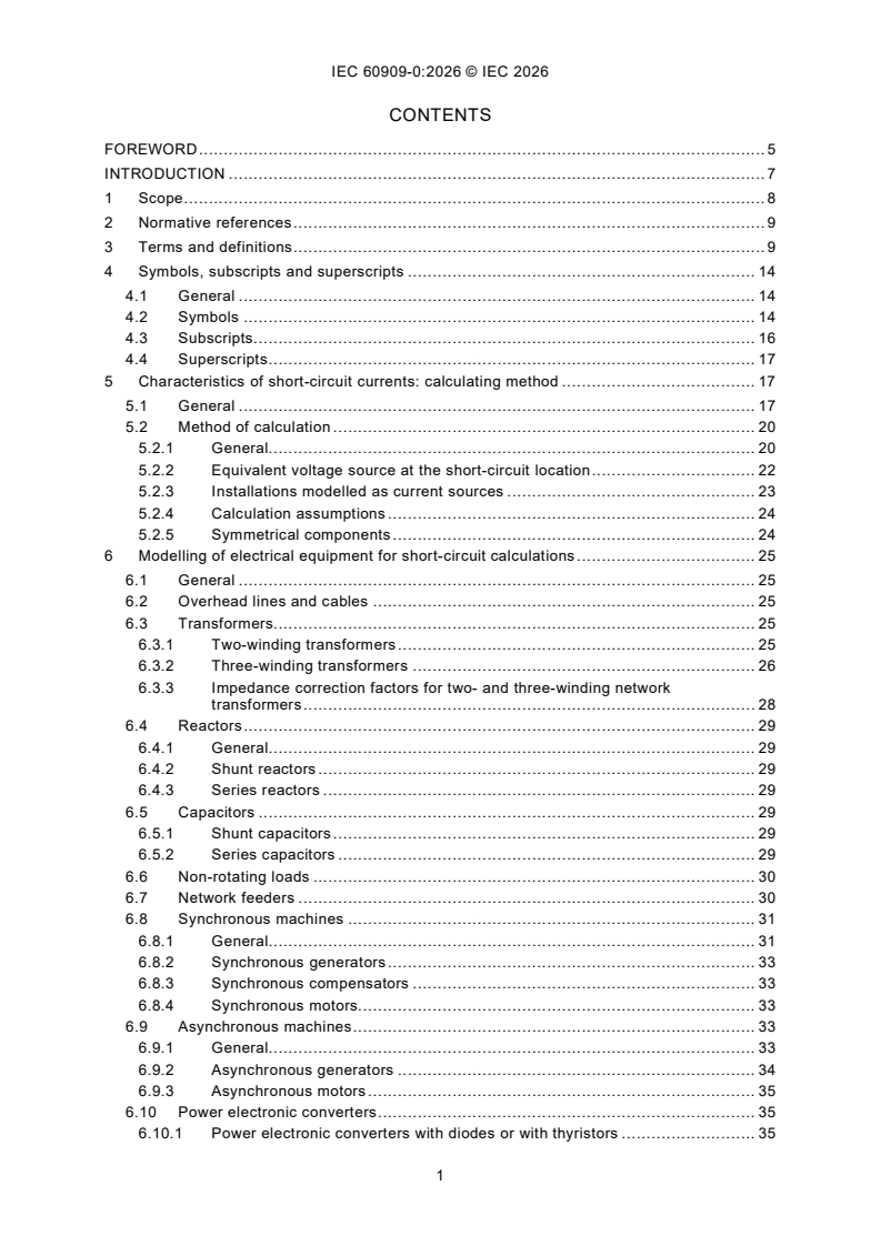
CONTENTS
FOREWORD . 5
INTRODUCTION . 7
1 Scope . 8
2 Normative references . 9
3 Terms and definitions . 9
4 Symbols, subscripts and superscripts . 14
4.1 General . 14
4.2 Symbols . 14
4.3 Subscripts . 16
4.4 Superscripts . 17
5 Characteristics of short-circuit currents: calculating method . 17
5.1 General . 17
5.2 Method of calculation . 20
5.2.1 General. 20
5.2.2 Equivalent voltage source at the short-circuit location . 22
5.2.3 Installations modelled as current sources . 23
5.2.4 Calculation assumptions . 24
5.2.5 Symmetrical components . 24
6 Modelling of electrical equipment for short-circuit calculations . 25
6.1 General . 25
6.2 Overhead lines and cables . 25
6.3 Transformers. 25
6.3.1 Two-winding transformers . 25
6.3.2 Three-winding transformers . 26
6.3.3 Impedance correction factors for two- and three-winding network
transformers . 28
6.4 Reactors . 29
6.4.1 General. 29
6.4.2 Shunt reactors . 29
6.4.3 Series reactors . 29
6.5 Capacitors . 29
6.5.1 Shunt capacitors . 29
6.5.2 Series capacitors . 29
6.6 Non-rotating loads . 30
6.7 Network feeders . 30
6.8 Synchronous machines . 31
6.8.1 General. 31
6.8.2 Synchronous generators . 33
6.8.3 Synchronous compensators . 33
6.8.4 Synchronous motors. 33
6.9 Asynchronous machines . 33
6.9.1 General. 33
6.9.2 Asynchronous generators . 34
6.9.3 Asynchronous motors . 35
6.10 Power electronic converters . 35
6.10.1 Power electronic converters with diodes or with thyristors . 35
6.10.2 Power electronic converters with semiconductor devices that can be
turned off, for example IGBT . 35
6.11 Power station units . 36
6.11.1 General. 36
6.11.2 Power station units with synchronous generators . 36
6.11.3 Power station units with asynchronous generator . 37
6.11.4 Power station units with doubly fed asynchronous generator . 37
6.11.5 Power station units with full-size converter . 38
6.12 Power plants . 39
6.13 Converter-fed motors . 40
6.13.1 General. 40
6.13.2 Converter-fed motors with grid-side converters using diodes or
thyristors . 41
6.13.3 Converter-fed motors with grid-side converters using semiconductor
devices that can be turned off, for example IGBT . 41
6.14 FACTS devices and HVDC transmission systems . 41
6.14.1 FACTS devices . 41
6.14.2 HVDC transmission systems . 41
7 Calculation of initial short-circuit currents . 42
7.1 Overview . 42
7.1.1 General. 42
7.1.2 Maximum short-circuit currents . 44
7.1.3 Minimum short-circuit currents. 45
7.2 Three-phase short circuit . 45
7.3 Line-to-line short circuit . 46
7.4 Line-to-line short circuit with earth connection . 47
7.5 Line-to-earth short circuit. 48
8 Calculation of peak short-circuit currents . 48
8.1 Single-fed three-phase short circuit . 48
8.2 Multiple-fed three-phase short circuits . 49
8.3 Unbalanced short circuits . 50
9 Calculation of symmetrical breaking currents . 51
9.1 Single-fed three-phase short circuits . 51
9.1.1 Symmetrical breaking currents fed by synchronous machines . 51
9.1.2 Symmetrical breaking current fed by asynchronous machines . 52
9.1.3 Symmetrical breaking current fed by power station units with doubly fed
asynchronous generator . 53
9.1.4 Symmetrical breaking current fed by power station units with full-size
converter . 54
9.1.5 Symmetrical breaking current fed by network feeders . 54
9.2 Multiple-fed three-phase short circuits . 54
9.3 Single-fed and multiple-fed unbalanced short circuits . 55
10 DC component and unbalanced asymmetrical breaking current . 55
11 Calculation of steady-state short-circuit currents . 56
11.1 General . 56
11.2 Three-phase short circuits . 56
11.2.1 Steady-state short-circuit currents single-fed by one synchronous
machine or one power station unit with synchronous generator . 56
11.2.2 Steady-state short-circuit currents of asynchronous machines . 59
11.2.3 Steady-state short-circuit currents of power station units with doubly fed
asynchronous generators . 59
11.2.4 Steady-state short-circuit currents of a power station unit with full-size
converter . 59
11.2.5 Steady-state short-circuit currents of a network feeder . 60
11.2.6 Steady-state short-circuit currents in case of multiple-fed short circuits . 60
11.3 Unbalanced single-fed and multiple-fed short circuits . 60
12 Short circuits at the low-voltage side of transformers, if one line conductor is
interrupted at the high-voltage side . 61
13 Terminal short circuits of asynchronous motors. 62
14 Thermal equivalent short-circuit current and Joule integral . 62
Annex A (informative) Short-circuit current inside a power station unit with
synchronous generator. 66
Annex B (normative) Formulas for the calculation of the factors m and n . 70
Bibliography . 71
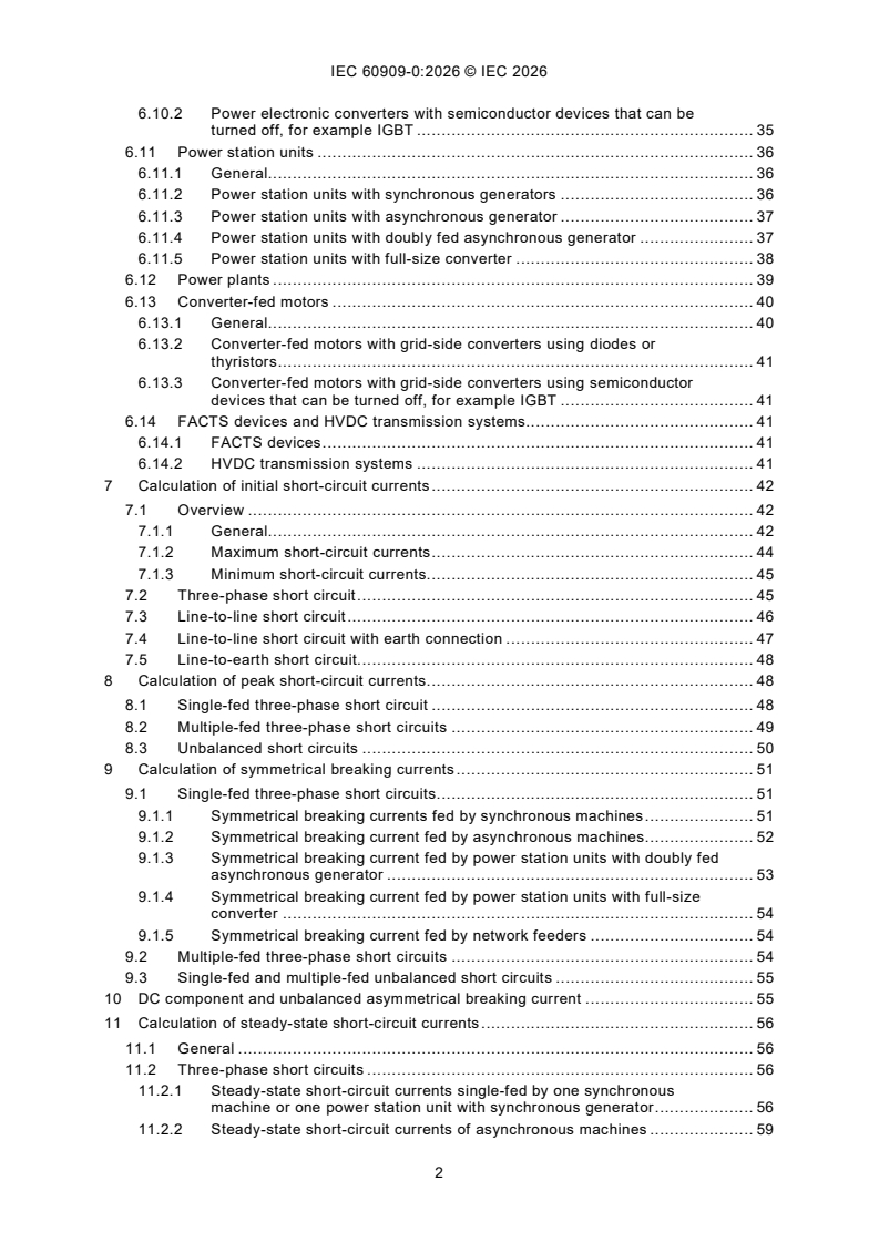
Figure 1 – Short-circuit current (schematic diagram) . 19
"
Figure 2 – Illustration for calculating the initial symmetrical short-circuit current I . 21
k
Figure 3 – Characterization of short circuits and their currents . 22
Figure 4 – Three-winding transformer . 27
Figure 5 – System diagram and equivalent circuit diagram for network feeders . 31
Figure 6 – Example of a power plant with short-circuit locations consisting of power
station units according to 6.11.3 to 6.11.5 . 39
Figure 7 – Equivalent circuit diagram (positive-sequence system) of a power plant with
power station units PA, PD, and PC for a short circuit at location F2 . 39
Figure 8 – Examples of single-fed short circuits . 43
Figure 9 – Example of multiple-fed short circuit . 44
Figure 10 – Factor κ for series circuit as a function of ratio R/X or X/R . 49
Figure 11 – Factor μ for calculation of symmetrical three-phase short-circuit breaking
current I fed by synchronous or asynchronous machines . 52
b
Figure 12 – Factor q for the calculation of the symmetrical three-phase short-circuit
breaking current of asynchronous machines . 53
Figure 13 – Factors λ and λ factors for cylindrical rotor synchronous machines . 58
min max
Figure 14 – Factors λ and λ for salient-pole synchronous machines . 58
min max
Figure 15 – Transformer secondary short-circuits, if one line (fuse) is opened on the
high-voltage side of a transformer Dy(n)5. 61
Figure 16 – Factor m for the heat effect of the DC component of the short-circuit
current . 64
Figure 17 – Factor n for the heat effect of the AC component of the short-circuit current . 65
Figure A.1 – Initial short-circuit currents and initial partial short-circuit currents for
three different short-circuit locations inside a power station unit with synchronous
generator . 68
Table 1 – Voltage factor c . 23
Table 2 – Factors α and β for the calculation of short-circuit currents with Formula (94),
rated transformation ratio t = U /U . 62
r rTHV rTLV
Table 3 – Calculation of short-circuit currents of asynchronous motors in the case of a
short circuit at the terminals. 63
INTERNATIONAL ELECTROTECHNICAL COMMISSION
____________
Short-circuit currents in three-phase AC systems -
Part 0: Calculation of currents
FOREWORD
1) The International Electrotechnical Commission (IEC) is a worldwide organization for standardization comprising
all national electrotechnical committees (IEC National Committees). The object of IEC is to promote international
co-operation on all questions concerning standardization in the electrical and electronic fields. To this end and
in addition to other activities, IEC publishes International Standards, Technical Specifications, Technical Reports,
Publicly Available Specifications (PAS) and Guides (hereafter referred to as “IEC Publication(s)”). Their
preparation is entrusted to technical committees; any IEC National Committee interested in the subject dealt with
may participate in this preparatory work. International, governmental and non-governmental organizations liaising
with the IEC also participate in this preparation. IEC collaborates closely with the International Organization for
Standardization (ISO) in accordance with conditions determined by agreement between the two organizations.
2) The formal decisions or agreements of IEC on technical matters express, as nearly as possible, an international
consensus of opinion on the relevant subjects since each technical committee has representation from all
interested IEC National Committees.
3) IEC Publications have the form of recommendations for international use and are accepted by IEC National
Committees in that sense. While all reasonable efforts are made to ensure that the technical content of IEC
Publications is accurate, IEC cannot be held responsible for the way in which they are used or for any
misinterpretation by any end user.
4) In order to promote international uniformity, IEC National Committees undertake to apply IEC Publications
transparently to the maximum extent possible in their national and regional publications. Any divergence between
any IEC Publication and the corresponding national or regional publication shall be clearly indicated in the latter.
5) IEC itself does not provide any attestation of conformity. Independent certification bodies provide conformity
assessment services and, in some areas, access to IEC marks of conformity. IEC is not responsible for any
services carried out by independent certification bodies.
6) All users should ensure that they have the latest edition of this publication.
7) No liability shall attach to IEC or its directors, employees, servants or agents including individual experts and
members of its technical committees and IEC National Committees for any personal injury, property damage or
other damage of any nature whatsoever, whether direct or indirect, or for costs (including legal fees) and
expenses arising out of the publication, use of, or reliance upon, this IEC Publication or any other IEC
Publications.
8) Attention is drawn to the Normative references cited in this publication. Use of the referenced publications is
indispensable for the correct application of this publication.
9) IEC draws attention to the possibility that the implementation of this document may involve the use of (a)
patent(s). [IEC takes no position concerning the evidence, validity or applicability of any claimed patent rights in
respect thereof. As of the date of publication of this document, IEC had not received notice of (a) patent(s), which
may be required to implement this document. However, implementers are cautioned that this may not represent
the latest information, which may be obtained from the patent database available at https://patents.iec.ch and/or
www.iso.org/patents. IEC shall not be held responsible for identifying any or all such patent rights.
IEC 60909-0 has been prepared by IEC technical committee 73: Short-circuit currents. It is an
International Standard.
This third edition cancels and replaces the second edition published in 2016. This edition
constitutes a technical revision.
This edition includes the following significant technical changes with respect to the previous
edition:
a) restructuring and complementing of the clauses, especially restructuring and updating of
Clause 6.
b) restructuring of subscripts.
The text of this International Standard is based on the following documents:
Draft Report on voting
73/220/CDV 73/236/RVC
Full information on the voting for its approval can be found in the report on voting indicated in
the above table.
The language used for the development of this International Standard is English.
This document was drafted in accordance with ISO/IEC Directives, Part 2, and developed in
accordance with ISO/IEC Directives, Part 1 and ISO/IEC Directives, IEC Supplement, available
at www.iec.ch/members_experts/refdocs. The main document types developed by IEC are
described in greater detail at www.iec.ch/publications.
A list of all parts in the IEC 60909 series, published under the general title Short-circuit currents
in three-phase AC systems, can be found on the IEC website.
The committee has decided that the contents of this document will remain unchanged until the
stability date indicated on the IEC website under webstore.iec.ch in the data related to the
specific document. At this date, the document will be
– reconfirmed,
– withdrawn, or
– revised.
INTRODUCTION
Main aim of IEC 60909-0 is calculation of maximum and minimum short-circuit currents of bolted
short circuits (see 5.2.4). Calculation results can serve as input for further evaluations such as
calculation of arcing current as described in, for example, IEEE 1584.
1 Scope
This part of IEC 60909 is applicable to the calculation of short-circuit currents
– in low-voltage three-phase AC systems,
– in high-voltage three-phase AC systems, and
– operating at a nominal frequency of 50 Hz or 60 Hz.
Systems at highest voltages of 550 kV and above with long transmission lines are outside the
scope of this document.
This document establishes a general, practicable and concise procedure leading to results
which are generally of acceptable accuracy. For this calculation method, an equivalent voltage
source at the short-circuit location is introduced. This does not exclude the use of special
methods, for example the superposition method, adjusted to particular circumstances, if they
give at least the same precision. The superposition method gives the short-circuit current
related to the one load flow presupposed. This method, therefore, does not necessarily lead to
the maximum respective minimum short-circuit current.
This document deals with the calculation of short-circuit currents in the case of balanced or
unbalanced short circuits.
A single line-to-earth fault occurring in networks with isolated or resonant earthing of the neutral
point is beyond the scope of this document.
For currents during two separate simultaneous single-phase line-to-earth short circuits in an
isolated neutral system or a resonance earthed neutral system, see IEC 60909-3.
Short-circuit currents and short-circuit impedances can also be determined by system tests, by
measurement on a network analyser, or numerical simulations with electromagnetic programs.
In existing low-voltage systems, it is possible to determine the short-circuit impedance on the
basis of measurements at the location of the prospective short circuit considered.
The calculation of the short-circuit impedance is in general based on the rated data of the
electrical equipment and the topological arrangement of the system and has the advantage of
being possible both for existing systems and for systems at the planning stage.
In general, two types of short-circuit currents, which differ in their magnitude, are considered:
– maximum short-circuit current which determines the capacity or rating of electrical
equipment;
– minimum short-circuit current which can be a basis, for example, for the selection of fuses,
for the setting of protective devices, and for checking the run-up of motors.
NOTE The current in a three-phase short circuit is assumed to be made simultaneously in all poles. Investigations
of non-simultaneous short circuits, which can lead to higher aperiodic components of short-circuit currents, are
beyond the scope of this document.
This document does not cover short-circuit currents deliberately created under controlled
conditions (short-circuit testing stations).
This document does not deal with the calculation of short-circuit currents in installations on
board ships and aeroplanes.
This document does not distinguish between grid-forming and grid-following converters for the
calculation of short-circuit currents.
2 Normative references
The following documents are referred to in the text in such a way that some or all of their content
constitutes requirements of this document. For dated references, only the edition cited applies.
For undated references, the latest edition of the referenced document (including any
amendments) applies.
IEC 60050-131, International Electrotechnical Vocabulary (IEV) - Part 131: Circuit theory
3 Terms and definitions
For the purposes of this document, the terms and definitions given in IEC 60050-131 and the
following apply.
ISO and IEC maintain terminology databases for use in standardization at the following
addresses:
– IEC Electropedia: available at https://www.electropedia.org/
– ISO Online browsing platform: available at https://www.iso.org/obp
3.1
short circuit
accidental or intentional conductive path between two or more conductive parts (e.g. three-
phase short circuit) forcing the electric potential differences between these conductive parts to
be equal or close to zero
[SOURCE: IEC 60050-151:2001, 151-12-04, modified – The parenthesis "(e.g. three-phase
short circuit)" has been added.]
3.1.1
line-to-line short circuit
two-phase short circuit
accidental or intentional conductive path between two line conductors with or without earth
connection
3.1.2
line-to-earth short circuit
single-phase short circuit
accidental or intentional conductive path in a solidly earthed neutral system or an impedance
earthed neutral system between a line conductor and local earth
3.2
short-circuit current
over-current resulting from a short circuit in an electric system
Note 1 to entry: It is necessary to distinguish between the short-circuit current at the short-circuit location and
partial short-circuit currents in the network branches (see Figure 3) at any point of the network.
3.3
prospective short-circuit current
current that would flow if the short circuit were replaced by an ideal connection of negligible
impedance without any change of the supply
Note 1 to entry: The current in a three-phase short circuit is assumed to be made simultaneously in all poles.
Investigations of non-simultaneous short circuits, which can lead to higher aperiodic components of short-circuit
current, are beyond the scope of this document.
3.4
symmetrical short-circuit current
RMS value of the AC symmetrical component of a prospective short-circuit current (see 3.3),
the aperiodic component of current, if any, being neglected
3.4.1
initial symmetrical short-circuit current
"
I
k
RMS value of the total AC symmetrical components of a prospective short-circuit current (see
3.3), applicable at the instant of short circuit if the impedance remains at zero-time value
SEE: Figure 1.
Note 1 to entry: The total initial short-circuit current is the sum of the short-circuit currents, caused by voltage and
current sources (see 3.4.2 and 3.4.3).
3.4.2
initial symmetrical short-circuit current
"
I
kVS
RMS value of the AC symmetrical components of a prospective short-circuit
current (see 3.3), caused by a voltage source, applicable at the instant of short circuit if the
impedance remains at zero-time value
3.4.3
initial symmetrical short-circuit current
"
I
kCS
RMS value of the AC symmetrical components of a prospective short-circuit
current (see 3.3), caused by a current source, applicable at the instant of short circuit if the
impedance remains at zero-time value
3.5
initial symmetrical short-circuit power
"
S
k
"
fictitious value determined as a product of the initial symmetrical short-circuit current I
k
(see 3.4.1), the nominal system voltage U (see 3.11) and the factor 3 :
n
""
S= 3⋅⋅UI
k nk
"
Note 1 to entry: The initial symmetrical short-circuit power S is not used for the calculation procedure in this
k
document.
3.6
decaying aperiodic component of short-circuit current
DC component
i
DC
mean value between the top and bottom envelope of a short-circuit current decaying from an
initial value to zero according to Figure 1
3.7
peak short-circuit current
i
p
maximum possible instantaneous value of the prospective short-circuit current
SEE: Figure 1.
Note 1 to entry: Sequential short circuits are not considered.
3.8
symmetrical short-circuit breaking current
I
b
RMS value of an integral cycle of the symmetrical AC component of the prospective short-circuit
current at the instant of contact separation of the first pole to open of a switching device
3.9
steady-state short-circuit current
I
k
RMS value of the short-circuit current which remains after the decay of the transient phenomena
SEE: Figure 1.
3.10
symmetrical locked-rotor current
I
LR
symmetrical RMS current of an asynchronous machine with locked rotor fed with rated voltage
U at rated frequency
rA
3.11
nominal system voltage
U
n
voltage (line-to-line) by which a system is designated, and to which certain operating
characteristics are referred
Note 1 to entry: Values are given in IEC 60038.
3.12
equivalent voltage source
cU /3
n
voltage of an ideal source applied at the short-circuit location for calculating the short-circuit
current according to 5.2.2
Note 1 to entry: The equivalent voltage source is the only active voltage of the network.
3.13
voltage factor
c
ratio between the equivalent voltage source and the nominal system voltage U divided by 3
n
Note 1 to entry: The values are given in Table 1.
Note 2 to entry: The introduction of a voltage factor c is necessary for various reasons: voltage variations depending
on time and place, changing of transformer taps, neglecting loads and capacitances by calculations according to
5.2.4 and the subtransient behaviour of generators and motors.
3.14
far-from-generator short circuit
short circuit during which the magnitude of the symmetrical AC component of the prospective
short-circuit current remains essentially constant
SEE: Figure 1 a).
3.15
near-to-generator short circuit
short circuit during which the magnitude of the symmetrical AC component of the prospective
short-circuit current decreases
SEE: Figure 1 b).
Note 1 to entry: A near-to-generator short circuit can be assumed if at least one synchronous machine contributes
a prospective initial symmetrical short-circuit current which is more than twice the machine's rated current, or a short
circuit to which asynchronous motors contribute more than 5 % of the initial symmetrical short-circuit current without
motors.
3.16
short-circuit impedances at the short-circuit location F
3.16.1
positive-sequence short-circuit impedance
Z
(1)
impedance of the positive-sequence system as viewed from the
short-circuit location
Note 1 to entry: See 5.2.5.
3.16.2
short-circuit impedance
Z
k
abbreviated expression for the positive-sequence short-circuit
impedance Z according to 3.16.1 for the calculation of three-phase short-circuit currents
(1)
3.16.3
negative-sequence short-circuit impedance
Z
(2)
impedance of the negative-sequence system as viewed from the
short-circuit location
Note 1 to entry: See 5.2.5.
3.16.4
zero-sequence short-circuit impedance
Z
(0)
impedance of the zero-sequence system as viewed from the short-
circuit location
Note 1 to entry: The zero-sequence short-circuit impedance includes three times the neutral-to-earth impedance
Z .
E
3.17
impedances of electrical equipment
3.17.1
positive-sequence impedance
Z
(1)
ratio of the line-to-neutral voltage to the short-circuit current of the
corresponding line conductor of electrical equipment when fed by a symmetrical positive-
sequence system of voltages
Note 1 to entry: See IEC TR 60909-4:2021, Clause 6.
Note 2 to entry: The index of symbol Z can be omitted if there is no possibility of confusion with the negative-
(1)
sequence and the zero-sequence impedances.
3.17.2
negative-sequence impedance
Z
(2)
ratio of the line-to-neutral voltage to the short-circuit current of the
corresponding line conductor of electrical equipment when fed by a symmetrical negative-
sequence system of voltages
Note 1 to entry: See IEC TR 60909-4:2021, Clause 6.
3.17.3
zero-sequence impedance
Z
(0)
ratio of the line-to-earth voltage to the short-circuit current of one line
conductor of electrical equipment when fed by an AC voltage source, if the three paralleled line
conductors are used for the outgoing current and either a fourth line or earth as a joint return,
or both
Note 1 to entry: See IEC TR 60909-4:2021, Clause 6.
3.18
subtransient reactance
"
X
d
effective reactance of a synchronous machine at the moment of short circuit
"
Note 1 to entry: For the calculation of short-circuit currents, the saturated value of X is taken.
d
3.19
minimum time delay
t
min
shortest time between the beginning of the short-circuit current and the contact separation of
the first pole to open of the switching device
Note 1 to entry: The time t is the sum of the shortest possible operating time of a protective relay and the shortest
min
opening time of a circuit-breaker. It does not take into account adjustable time delays of tripping devices.
3.20
thermal equivalent short-circuit current
I
th
RMS value of a current having the same thermal effect and the same duration as the actual
short-circuit current, which can contain a DC component and can subside in time
3.21
short-circuit current of full-size converters
current source of full-size converters
3.21.1
source current for three phase short circuits
I
kPC
size converter and current regulation in case of three-phase short circuit at the high-voltage
side of the step-up transformer
3.21.2
source current for line-to-line short circuits
I
(1)k2PC
power station with full-size converter and current regulation in case of a line-to-line short circuit
or a line-to-line short circuit with earth connection at the high-voltage side of the step-up
transformer
3.21.3
source current for line-to-earth short circuits
I
(1)k1PC
a power station with full-size converter and current regulation in case of a line-to-earth short-
circuit at the high-voltage side of the step-up transformer
3.22
impedance of the nodal impedances matrix
Z , Z , Z
(1)ii (2ii) (0)ii
diagonal elements of the positive-sequence, or negative-sequence or zero-
sequence nodal impedances matrix for the short-circuit location i
3.23
impedance of the nodal impedances matrix
Z
(1)ij
elements of the positive-sequence nodal impedances matrix, where i is
the node of the short circuit and j the node where the high-voltage side of a power station unit
with full-size converter is connected
4 Symbols, subscripts and superscripts
4.1 General
The formulas given in this document are written without specifying units. The symbols represent
physical quantities possessing both numerical values and dimensions that are independent of
units, provided a consistent unit system is chosen, for example the international system of units
(SI). Symbols of complex quantities are underlined, for example Z = R + jX.
4.2 Symbols
j2π/3
a complex operator a = e
A initial value of the DC component i
DC
c voltage factor
cU /3 equivalent voltage source (RMS)
n
f frequency (50 Hz or 60 Hz)
f equivalent frequency to calculate the peak short-circuit current
c
I symmetrical short-circuit breaking current (RMS)
b
i aperiodic or DC component of short-circuit current
DC
I steady-state short-circuit current (RMS)
k
I steady-state short-circuit current of a generator with compound excitation
kCE
symmetrical locked-rotor current of an asynchronous generator or motor
I
LR
i peak short-circuit current
p
I rated current of electrical equipment
r
I thermal equivalent short-circuit current
th
"
I initial symmetrical short-circuit current (RMS)
k
"
I initial symmetrical short-circuit current (RMS) caused by current sources
kCS
"
I
initial symmetrical short-circuit current (RMS) caused by voltage sources
kVS
κ correction factor for impedances
m factor for the heat effect of the DC component
n factor for the heat effect of the AC component
p pair of poles of an asynchronous machine
p range of synchronous generator voltage regulation
S
P total loss in transformer windings at rated current
krT
P rated mechanical power of an asynchronous machine (P = S cos(φ )η )
rA rA rA tA rA
p range of transformer voltage adjustment
T
q factor for the calculation of breaking current of asynchronous machines
q nominal cross-section
n
r relative resistance of a transformer at rated transformation ratio in per unit
rT
R resp. r resistance, absolute respectively relative value
S rated apparent power of electrical equipment
r
T duration of the short-circuit current
k
t minimum time delay
min
t rated transformation ratio (tap-changer in main position); t ≥ 1
r r
u rated short-circuit voltage of a transformer in per unit
kr
U , U , U positive-, negative-, zero-sequence voltage
(1) (2) (0)
U highest voltage for equipment, line-to-line (RMS)
m
U nominal system voltage, line-to-line (RMS)
n
U rated voltage, line-to-line (RMS)
r
"
"
X resp. X saturated subtransient reactance of a synchronous machine, direct axis
d q
respectively quadrature axis
X resp. x reactance, absolute respectively relative value
X resp. X synchronous reactance, direct axis respectively quadrature axis
d q
x unsaturated synchronous reactance, relative value
d
X fictitious reactance of a generator with compound excitation in the case of
dCE
steady-state short circuit at the terminals (poles)
x saturated synchronous reactance, relative value, reciprocal of the saturated
dsat
no-load short-circuit ratio
x relative reactance of a transformer at rated transformation ratio in per unit
rT
Z resp. z impedance, absolute respectively relative value
Z zero-sequence short-circuit impedance
(0)
Z positive-sequence short-circuit impedance
(1)
Z negative-sequence short-circuit impedance
(2)
Z short-circuit impedance of a three-phase AC system at the short-circuit
k
location
ϑ conductor temperature at the end of the short circuit
e
α, β factors for the calculation of short-circuit currents, if one conductor is
interrupted
η efficiency of asynchronous machines
rA
φ phase angle
κ factor for the calculation of the peak short-circuit current
λ factor for the calculation of the steady-state short-circuit current
μ factor for the calculation of the symmetrical short-circuit breaking current
μ absolute permeability of vacuum, μ = 4π × 10- H/km
0 0
ρ resistivity
01 positive-sequence neutral reference
02 negative-sequence neutral reference
00 zero-sequence neutral reference
4.3 Subscripts
(1) positive-sequence component
(2) negative-sequence component
(0) zero-sequence component
A asynchronous machine
AC alternating current
AG asynchronous generator
AM asynchronous motor or group of asynchronous motors
AM0 without asynchronous motors
asym asymmetrical
B busbar
c equivalent frequency
C converter
CE generator with compound excitation
CS current source
DC direct current
E earth
f fictitious
F short-circuit location
HV high-voltage, high-voltage side of a transformer
k or k3 three-phase short circuit; see Figure 3 a)
K corrected impedances with the impedance correction factors
k1 line-to-earth short circuit, line-to-neutral short circuit; see Figure 3 d)
k2 line-to-line short circuit; see Figure 3 b)
k2EL2 line-to-line short circuit with earth connection; see Figure 3 c)
k2EL3 line-to-line short circuit with earth connection; see Figure 3 c)
kE2E line-to-line short circuit with earth connection; see Figure 3 c)
L line
L1, L2, L3 line conductors of a three-phase AC system
LV low-voltage, low-voltage side of a transformer
max maximum
min minimum
MV medium-voltage, medium-voltage side of a transformer
N network
n nominal value
PA power station with asynchronous generator
PC power station with full-size converter
PD power station with doubly fed asynchronous generator
PP power plant
PPA power plant with asynchronous generator
PPC power plant with full-size converter
PPD power station with doubly fed asynchr
...
IEC 60909-0 ®
Edition 3.0 2026-07
NORME
INTERNATIONALE
Courants de court-circuit dans les réseaux triphasés à courant alternatif -
Partie 0: Calcul des courants
ICS 17.220.01; 29.240.20 ISBN 978-2-8327-1382-2
Droits de reproduction réservés. Sauf indication contraire, aucune partie de cette publication ne peut être reproduite ni
utilisée sous quelque forme que ce soit et par aucun procédé, électronique ou mécanique, y compris la photocopie et
les microfilms, sans l'accord écrit de l'IEC ou du Comité national de l'IEC du pays du demandeur. Si vous avez des
questions sur le copyright de l'IEC ou si vous désirez obtenir des droits supplémentaires sur cette publication, utilisez
les coordonnées ci-après ou contactez le Comité national de l'IEC de votre pays de résidence.
IEC Secretariat Tel.: +41 22 919 02 11
3, rue de Varembé info@iec.ch
CH-1211 Geneva 20 www.iec.ch
Switzerland
A propos de l'IEC
La Commission Electrotechnique Internationale (IEC) est la première organisation mondiale qui élabore et publie des
Normes internationales pour tout ce qui a trait à l'électricité, à l'électronique et aux technologies apparentées.
A propos des publications IEC
Le contenu technique des publications IEC est constamment revu. Veuillez vous assurer que vous possédez l’édition la
plus récente, un corrigendum ou amendement peut avoir été publié.
Recherche de publications IEC - IEC Products & Services Portal - products.iec.ch
webstore.iec.ch/advsearchform Découvrez notre puissant moteur de recherche et consultez
La recherche avancée permet de trouver des publications gratuitement tous les aperçus des publications, symboles
IEC en utilisant différents critères (numéro de référence, graphiques et le glossaire. Avec un abonnement, vous aurez
texte, comité d’études, …). Elle donne aussi des toujours accès à un contenu à jour adapté à vos besoins.
informations sur les projets et les publications remplacées
ou retirées. Electropedia - www.electropedia.org
Le premier dictionnaire d'électrotechnologie en ligne au
IEC Just Published - webstore.iec.ch/justpublished monde, avec plus de 22 500 articles terminologiques en
Restez informé sur les nouvelles publications IEC. Just anglais et en français, ainsi que les termes équivalents
Published détaille les nouvelles publications parues. dans 25 langues additionnelles. Egalement appelé
Disponible en ligne et une fois par mois par email. Vocabulaire Electrotechnique International (IEV) en ligne.
Service Clients - webstore.iec.ch/csc
Si vous désirez nous donner des commentaires sur cette
publication ou si vous avez des questions contactez-
nous: sales@iec.ch.
SOMMAIRE
AVANT-PROPOS . 5
INTRODUCTION . 7
1 Domaine d’application . 8
2 Références normatives . 9
3 Termes et définitions. 9
4 Symboles, indices inférieurs et supérieurs . 14
4.1 Généralités . 14
4.2 Symboles . 15
4.3 Indices . 16
4.4 Indices supérieurs . 18
5 Caractéristiques des courants de court-circuit: méthode de calcul . 18
5.1 Généralités . 18
5.2 Méthode de calcul. 21
5.2.1 Généralités . 21
5.2.2 Source de tension équivalente au point de court-circuit . 23
5.2.3 Installations modélisées comme sources de courant . 24
5.2.4 Hypothèses de calcul . 25
5.2.5 Composantes symétriques . 25
6 Modélisation d’équipements électriques pour les calculs de courts-circuits . 26
6.1 Généralités . 26
6.2 Lignes aériennes et câbles . 26
6.3 Transformateurs . 26
6.3.1 Transformateurs à deux enroulements . 26
6.3.2 Transformateurs à trois enroulements . 27
6.3.3 Facteurs de correction d’impédance pour transformateurs de réseau à
deux et trois enroulements . 29
6.4 Bobines d’inductance . 30
6.4.1 Généralités . 30
6.4.2 Bobines d’inductance shunt . 30
6.4.3 Bobines d’inductance série . 31
6.5 Condensateurs . 31
6.5.1 Condensateurs-shunt . 31
6.5.2 Condensateurs-série . 31
6.6 Charges non rotatives . 31
6.7 Réseaux d’alimentation . 31
6.8 Machines synchrones . 33
6.8.1 Généralités . 33
6.8.2 Alternateurs synchrones . 34
6.8.3 Compensateurs synchrones . 35
6.8.4 Moteurs synchrones . 35
6.9 Machines asynchrones . 35
6.9.1 Généralités . 35
6.9.2 Alternateurs asynchrones . 36
6.9.3 Moteurs asynchrones . 36
6.10 Convertisseurs électroniques de puissance . 37
6.10.1 Convertisseurs électroniques de puissance avec diodes ou thyristors. 37
6.10.2 Convertisseurs électroniques de puissance avec dispositifs à
semiconducteurs pouvant être mis hors tension, par exemple IGBT . 37
6.11 Unités de groupe de production . 37
6.11.1 Généralités . 37
6.11.2 Groupes de production avec alternateurs synchrones . 37
6.11.3 Groupes de production avec alternateur asynchrone . 39
6.11.4 Groupes de production avec alternateur asynchrone à double
alimentation . 39
6.11.5 Groupes de production avec convertisseur grande capacité . 40
6.12 Centrales électriques . 40
6.13 Moteurs alimentés par convertisseur. 42
6.13.1 Généralités . 42
6.13.2 Moteurs alimentés par convertisseur avec convertisseurs côté réseau
utilisant des diodes ou des thyristors . 42
6.13.3 Moteurs alimentés par convertisseur avec convertisseurs côté réseau
utilisant des dispositifs à semiconducteurs pouvant être mis hors
tension, par exemple IGBT . 43
6.14 Appareils FACTS et systèmes de transmission HVDC . 43
6.14.1 Appareils FACTS . 43
6.14.2 Systèmes de transmission en courant continu haute tension (HVDC) . 44
7 Calcul des courants de court-circuit initiaux . 44
7.1 Vue d’ensemble . 44
7.1.1 Généralités . 44
7.1.2 Courants de court-circuit maximaux . 47
7.1.3 Courants de court-circuit minimaux . 47
7.2 Court-circuit triphasé . 48
7.3 Court-circuit entre phases. 48
7.4 Court-circuit entre phases avec mise à la terre . 49
7.5 Court-circuit monophasé. 50
8 Calcul du courant de court-circuit de crête . 50
8.1 Court-circuit triphasé à alimentation unique . 50
8.2 Courts-circuits triphasés à alimentation multiple . 52
8.3 Courts-circuits dissymétriques . 53
9 Calcul des courants symétriques coupés . 53
9.1 Courts-circuits triphasés à alimentation unique . 53
9.1.1 Courants symétriques coupés alimentés par des machines synchrones . 53
9.1.2 Courant symétrique coupé alimenté par des machines asynchrones . 54
9.1.3 Courant symétrique coupé alimenté par des groupes de production
avec alternateur asynchrone à double alimentation . 56
9.1.4 Courant symétrique coupé alimenté par des groupes de production
avec convertisseur grande capacité . 56
9.1.5 Courant symétrique coupé alimenté par le réseau d’alimentation . 57
9.2 Courts-circuits triphasés à alimentation multiple . 57
9.3 Courts-circuits dissymétriques à alimentation unique et multiple . 58
10 Composante continue et courant coupé dissymétrique. 58
11 Calcul des courants de court-circuit permanents . 59
11.1 Généralités . 59
11.2 Courts-circuits triphasés . 59
11.2.1 Courants de court-circuit permanents alimentés par une seule machine
synchrone ou un groupe de production avec alternateur synchrone . 59
11.2.2 Courants de court-circuit permanents de machines asynchrones . 62
11.2.3 Courants de court-circuit permanents de groupes de production avec
alternateur asynchrone à double alimentation . 62
11.2.4 Courants de court-circuit permanents d’un groupe de production avec
convertisseur grande capacité . 62
11.2.5 Courants de court-circuit permanents d’un réseau d’alimentation . 63
11.2.6 Courants de court-circuit permanents en cas de courts-circuits à
alimentation multiple . 63
11.3 Courts-circuits dissymétriques à alimentation unique et multiple . 63
12 Courts-circuits de transformateur du côté basse tension, si une phase est ouverte
côté haute tension . 64
13 Courts-circuits aux bornes des moteurs asynchrones . 65
14 Courant de court-circuit équivalent thermique et intégrale de Joule . 65
Annexe A (informative) Courant de court-circuit alimenté par un groupe de production
avec alternateur synchrone . 69
Annexe B (normative) Formules pour le calcul des facteurs m et n . 73
Bibliographie . 74
Figure 1 – Courant de court-circuit (schéma de principe) . 20
"
Figure 2 – Représentation du calcul du courant de court-circuit symétrique initial I . 22
k
Figure 3 – Caractérisation des courts-circuits et de leurs courants. 23
Figure 4 – Transformateur à trois enroulements . 29
Figure 5 – Schéma du réseau et schéma de circuit équivalent pour réseaux
d’alimentation . 32
Figure 6 – Exemple d’une centrale électrique avec points de court-circuit constituée de
groupes de production selon 6.11.3 à 6.11.5 . 41
Figure 7 – Schéma d’équivalence des circuits (système à séquence positive) d’une
centrale électrique avec groupes de production PA, PD et PC pour un court-circuit au
point F2 . 41
Figure 8 – Exemples de courts-circuits à alimentation unique . 45
Figure 9 – Exemples de courts-circuits à alimentation multiple . 46
Figure 10 – Facteur κ pour les circuits en série en fonction du rapport R/X ou X/R . 51
Figure 11 – Facteur μ pour le calcul du courant de court-circuit symétrique coupé I
b
alimenté par des machines synchrones ou asynchrones . 54
Figure 12 – Facteur q pour le calcul du courant de court-circuit symétrique coupé
triphasé de machines asynchrones . 56
Figure 13 – Facteurs λ et λ pour machines synchrones à rotor cylindrique . 61
min max
Figure 14 – Facteurs λ et facteurs λ pour machines synchrones à pôles
min max
saillants . 61
Figure 15 – Courts-circuits au secondaire des transformateurs, si une phase (fusible)
est ouverte du côté haute tension d’un transformateur Dy(n)5 . 64
Figure 16 – Facteur m pour l’effet thermique de la composante continue du courant de
court-circuit. 67
Figure 17 – Facteur n pour l’effet thermique de la composante alternative du courant
de court-circuit . 68
Figure A.1 – Courants de court-circuit initiaux et courants de court-circuit partiels
initiaux pour trois emplacements de court-circuit différents, à l’intérieur d’un groupe de
production avec alternateur synchrone . 71
Tableau 1 – Facteur de tension c . 24
Tableau 2 – Facteurs α et β pour le calcul des courants de court-circuit à l’aide de la
Formule (94), rapport de transformation assigné t = U /U . 65
r rTHV rTLV
Tableau 3 – Calcul des courants de court-circuit des moteurs asynchrones dans le cas
d’un court-circuit aux bornes . 66
COMMISSION ÉLECTROTECHNIQUE INTERNATIONALE
____________
Courants de court-circuit dans les réseaux triphasés à courant alternatif -
Partie 0: Calcul des courants
AVANT-PROPOS
1) La Commission Électrotechnique Internationale (IEC) est une organisation mondiale de normalisation composée
de l’ensemble des comités électrotechniques nationaux (Comités nationaux de l’IEC). L’IEC a pour objet de
favoriser la coopération internationale pour toutes les questions de normalisation dans les domaines de
l’électricité et de l’électronique. À cet effet, l’IEC – entre autres activités – publie des Normes internationales,
des Spécifications techniques, des Rapports techniques, des Spécifications accessibles au public (PAS) et des
Guides (ci-après dénommés "Publication(s) de l’IEC"). Leur élaboration est confiée à des comités d’études, aux
travaux desquels tout Comité national intéressé par le sujet traité peut participer. Les organisations
internationales, gouvernementales et non gouvernementales, en liaison avec l’IEC, participent également aux
travaux. L’IEC collabore étroitement avec l’Organisation Internationale de Normalisation (ISO), selon des
conditions fixées par accord entre les deux organisations.
2) Les décisions ou accords officiels de l’IEC concernant les questions techniques représentent, dans la mesure du
possible, un accord international sur les sujets étudiés, étant donné que les Comités nationaux de l’IEC intéressés
sont représentés dans chaque comité d’études.
3) Les Publications de l’IEC se présentent sous la forme de recommandations internationales et sont agréées
comme telles par les Comités nationaux de l’IEC. Tous les efforts raisonnables sont entrepris afin que l’IEC
s’assure de l’exactitude du contenu technique de ses publications; l’IEC ne peut pas être tenue responsable de
l’éventuelle mauvaise utilisation ou interprétation qui en est faite par un quelconque utilisateur final.
4) Dans le but d’encourager l’uniformité internationale, les Comités nationaux de l’IEC s’engagent, dans toute la
mesure possible, à appliquer de façon transparente les Publications de l’IEC dans leurs publications nationales
et régionales. Toutes divergences entre toutes Publications de l’IEC et toutes publications nationales ou
régionales correspondantes doivent être indiquées en termes clairs dans ces dernières.
5) L’IEC elle-même ne fournit aucune attestation de conformité. Des organismes de certification indépendants
fournissent des services d’évaluation de conformité et, dans certains secteurs, accèdent aux marques de
conformité de l’IEC. L’IEC n’est responsable d’aucun des services effectués par les organismes de certification
indépendants.
6) Tous les utilisateurs doivent s’assurer qu’ils sont en possession de la dernière édition de cette publication.
7) Aucune responsabilité ne doit être imputée à l’IEC, à ses administrateurs, employés, auxiliaires ou mandataires,
y compris ses experts particuliers et les membres de ses comités d’études et des Comités nationaux de l’IEC,
pour tout préjudice causé en cas de dommages corporels et matériels, ou de tout autre dommage de quelque
nature que ce soit, directe ou indirecte, ou pour supporter les coûts (y compris les frais de justice) et les dépenses
découlant de la publication ou de l’utilisation de cette Publication de l’IEC ou de toute autre Publication de l’IEC,
ou au crédit qui lui est accordé.
8) L’attention est attirée sur les références normatives citées dans cette publication. L’utilisation de publications
référencées est obligatoire pour une application correcte de la présente publication.
9) L’IEC attire l’attention sur le fait que la mise en application du présent document peut entraîner l’utilisation d’un
ou de plusieurs brevets. L’IEC ne prend pas position quant à la preuve, à la validité et à l’applicabilité de tout
droit de brevet revendiqué à cet égard. À la date de publication du présent document, l’IEC n’avait pas reçu
notification qu’un ou plusieurs brevets pouvaient être nécessaires à sa mise en application. Toutefois, il y a lieu
d’avertir les responsables de la mise en application du présent document que des informations plus récentes
sont susceptibles de figurer dans la base de données de brevets, disponible à l’adresse https://patents.iec.ch
et/ou www.iso.org/patents. L’IEC ne saurait être tenue pour responsable de ne pas avoir identifié de tels droits
de brevet.
L’IEC 60909-0 a été établie par le comité d’études 73 de l’IEC: Courants de court-circuit. Il
s’agit d’une Norme internationale.
Cette troisième édition annule et remplace la deuxième édition parue en 2016. Cette édition
constitue une révision technique.
Cette édition inclut les modifications techniques majeures suivantes par rapport à l’édition
précédente:
a) restructuration et complétion des articles, notamment restructuration et actualisation de
l’Article 6;
b) restructuration des indices.
Le texte de cette Norme internationale est issu des documents suivants:
Projet Rapport de vote
73/220/CDV 73/236/RVC
Le rapport de vote indiqué dans le tableau ci-dessus donne toute information sur le vote ayant
abouti à son approbation.
La langue employée pour l’élaboration de cette Norme internationale est l’anglais.
Ce document a été rédigé selon les Directives ISO/IEC, Partie 2, il a été développé selon les
Directives ISO/IEC, Partie 1 et les Directives ISO/IEC, Supplément IEC, disponibles sous
www.iec.ch/members_experts/refdocs. Les principaux types de documents développés par
l’IEC sont décrits plus en détail sous www.iec.ch/publications.
Une liste de toutes les parties de la série IEC 60909, publiées sous le titre général Courants
de court-circuit dans les réseaux triphasés à courant alternatif, se trouve sur le site Web de
l’IEC.
Le comité a décidé que le contenu de ce document ne sera pas modifié avant la date de stabilité
indiquée sur le site web de l’IEC sous webstore.iec.ch dans les données relatives au document
recherché. À cette date, le document sera
– reconduit,
– supprimé, ou
– révisé.
INTRODUCTION
L'IEC 60909-0 a pour principal objectif le calcul des courants de court-circuit maximal et
minimal des courts-circuits boulonnés (voir 5.2.4). Les résultats du calcul peuvent servir
d’entrée pour d’autres évaluations telles que le calcul du courant d’arc, comme décrit par
exemple dans l’IEEE 1584.
1 Domaine d’application
La présente partie de l’IEC 60909 est applicable au calcul des courants de court-circuit
– dans les réseaux triphasés basse tension en courant alternatif,
– dans les réseaux triphasés haute tension en courant alternatif, et
– fonctionnant à une fréquence nominale de 50 Hz ou de 60 Hz.
Les réseaux soumis aux tensions les plus élevées (550 kV et plus) et associés à des lignes de
transport de grande longueur ne relèvent pas du domaine d’application du présent document.
Le présent document établit une procédure générale, réalisable et concise, qui génère des
résultats qui sont en général d’une exactitude acceptable. Pour établir cette méthode de calcul,
une source de tension équivalente au point de court-circuit est introduite. Cela n’exclut pas
l’utilisation de méthodes particulières, par exemple la méthode de superposition, appliquées à
des cas précis, si elles conduisent à une précision au moins égale. La méthode de superposition
donne le courant de court-circuit par rapport au flux de puissance présupposé. C’est pourquoi
cette méthode ne permet pas nécessairement d’obtenir le courant de court-circuit maximal
respectivement associé au courant de court-circuit minimal.
Le présent document traite du calcul des courants de court-circuit dans le cas de courts-circuits
symétriques et dissymétriques.
Un défaut simple entre phase et terre se produisant dans des réseaux avec mise à la terre
isolée ou en résonance du point neutre ne relève pas du domaine d’application du présent
document.
Pour les courants existant pendant deux courts-circuits distincts simultanés entre phase et terre
dans un réseau à neutre isolé ou dans un réseau à neutre compensé, voir l’IEC 60909-3.
Les courants et impédances de court-circuit peuvent également être déterminés par des essais
en réseau, par des mesures sur un analyseur de réseau ou par des simulations numériques
employant des programmes électromagnétiques. Dans les réseaux basse tension existants,
l’impédance de court-circuit peut être déterminée à partir des mesures effectuées au point de
court-circuit présumé.
Le calcul de l’impédance de court-circuit s’effectue en général à partir des valeurs assignées
des matériels électriques et de la configuration du réseau, et présente l’avantage d’être
susceptible de s’appliquer aussi bien aux réseaux existants qu’aux réseaux à l’état de projet.
En général, deux types de courants de court-circuit d’amplitude différente sont pris en compte
dans les calculs:
– courant de court-circuit maximal, qui détermine la capacité ou le régime assigné du matériel
électrique;
– courant de court-circuit minimal, qui peut servir, par exemple, au choix des fusibles et au
calibrage des dispositifs de protection ainsi qu’au contrôle de la mise en marche des
moteurs.
NOTE Lors d’un court-circuit triphasé, le courant s’établit, par hypothèse, simultanément sur les trois phases. Les
recherches concernant les courts-circuits non simultanés qui peuvent conduire à des composantes apériodiques
majorées du courant de court-circuit ne relèvent pas du domaine d’application du présent document.
Le présent document ne couvre pas le cas de courants de court-circuit provoqués
intentionnellement et sous contrôle (stations d’essais de court-circuit).
Le présent document ne traite pas du calcul des courants de court-circuit dans les installations
à bord des navires et des avions.
Pour le calcul des courants de court-circuit, le présent document ne fait pas de distinction entre
les convertisseurs autonomes (ou "grid-forming") et les convertisseurs passifs (ou
"grid-following").
2 Références normatives
Les documents suivants sont cités dans le texte de sorte qu’ils constituent, pour tout ou partie
de leur contenu, des exigences du présent document. Pour les références datées, seule
l’édition citée s’applique. Pour les références non datées, la dernière édition du document de
référence s’applique (y compris les éventuels amendements).
IEC 60050-131, Vocabulaire Electrotechnique International (IEV) - Partie 131: Théorie des
circuits
3 Termes et définitions
Pour les besoins du présent document, les termes et définitions de l’IEC 60050-131, ainsi que
les suivants, s’appliquent.
L’ISO et l’IEC tiennent à jour des bases de données terminologiques destinées à être utilisées
en normalisation, consultables aux adresses suivantes:
– IEC Electropedia: disponible à l’adresse https://www.electropedia.org/
– ISO Online browsing platform: disponible à l’adresse https://www.iso.org/obp
3.1
court-circuit
chemin conducteur accidentel ou intentionnel entre deux ou plusieurs parties conductrices
(p. ex. court-circuit triphasé), forçant les différences de potentiel électriques entre ces parties
conductrices à être nulles ou proches de zéro
[SOURCE: IEC 60050-151:2001, 151-12-04, modifié – L’expression entre parenthèses "(par
exemple court-circuit triphasé)" a été ajoutée.]
3.1.1
court-circuit entre phases
court-circuit biphasé
chemin conducteur accidentel ou intentionnel entre deux conducteurs de ligne à la terre ou
isolés
3.1.2
court-circuit phase-terre
court-circuit monophasé
chemin conducteur accidentel ou intentionnel dans un réseau à neutre mis directement à la
terre ou à neutre impédant entre un conducteur de phase et la terre locale
3.2
courant de court-circuit
surintensité résultant d’un court-circuit dans un circuit électrique
Note 1 à l’article: Il est nécessaire de faire une distinction entre le courant de court-circuit au point de court-circuit
et les courants de court-circuit partiels dans les branches du réseau (voir la Figure 3) en un point quelconque du
réseau.
3.3
courant de court-circuit présumé
courant qui circulerait si le court-circuit était remplacé par une connexion idéale d’impédance
négligeable sans modification de l’alimentation
Note 1 à l’article: Lors d’un court-circuit triphasé, le courant s’établit, par hypothèse, simultanément sur les trois
phases. Les recherches concernant les courts-circuits non simultanés qui peuvent conduire à des composantes
apériodiques majorées du courant de court-circuit ne relèvent pas du domaine d’application du présent document.
3.4
courant de court-circuit symétrique
valeur efficace de la composante symétrique alternative d’un courant de court-circuit présumé
(voir 3.3), l’éventuelle composante apériodique du courant étant ignorée
3.4.1
courant de court-circuit symétrique initial
"
I
k
valeur efficace des composantes symétriques alternatives totales d’un courant de court-circuit
présumé (voir 3.3), à l’instant d’apparition du court-circuit, si l’impédance conserve sa valeur
initiale
VOIR: Figure 1.
Note 1 à l’article: Le courant de court-circuit initial total correspond à la somme des courants de court-circuit,
causés par les sources de tension et de courant (voir 3.4.2 et 3.4.3).
3.4.2
courant de court-circuit symétrique initial
"
I
kVS
court-circuit présumé (voir 3.3), causé par une source de tension, à l’instant d’apparition du
court-circuit, si l’impédance conserve sa valeur initiale
3.4.3
courant de court-circuit symétrique initial
"
I
kCS
de court-circuit présumé (voir 3.3), causé par une source de courant, à l’instant d’apparition du
court-circuit, si l’impédance conserve sa valeur initiale
3.5
puissance de court-circuit symétrique initiale
"
S
k
"
valeur fictive définie comme le produit du courant de court-circuit symétrique initial I
k
(voir 3.4.1), la tension nominale du réseau U (voir 3.11) et le facteur 3 :
n
""
S= 3⋅⋅UI
k nk
"
Note 1 à l’article: La puissance de court-circuit symétrique initiale S n’est pas utilisée dans la méthode de calcul
k
du présent document.
3.6
composante apériodique décroissante du courant de court-circuit
Composante continue
i
DC
valeur moyenne des enveloppes inférieure et supérieure d’un courant de court-circuit
décroissant de sa valeur initiale vers zéro, conformément à Figure 1
3.7
valeur de crête du courant de court-circuit
i
p
valeur instantanée maximale possible du courant de court-circuit présumé
Voir: Figure 1.
Note 1 à l'article: Les défauts répétitifs ne sont pas pris en considération.
3.8
courant de court-circuit symétrique coupé
I
b
valeur efficace d’un cycle complet de la composante alternative symétrique du courant de court-
circuit présumé à l’instant de la séparation d’ouverture des contacts du premier pôle de
l’appareil de connexion
3.9
courant de court-circuit permanent
I
k
valeur efficace du courant de court-circuit se maintenant, après extinction des phénomènes
transitoires
Voir: Figure 1.
3.10
courant symétrique à rotor bloqué
I
LR
valeur efficace du courant symétrique d’une machine asynchrone alimentée sous sa tension
assignée U à fréquence assignée et dont le rotor est bloqué
rA
3.11
tension nominale du réseau
U
n
tension (entre phases) par laquelle un réseau est désigné et à laquelle il est fait référence pour
certaines caractéristiques fonctionnelles
Note 1 à l’article: Les valeurs sont données dans l’IEC 60038.
3.12
source de tension équivalente
cU /3
n
tension d’une source idéale appliquée au point de court-circuit permettant de calculer le courant
de court-circuit comme indiqué en 5.2.2
Note 1 à l’article: La source de tension équivalente est la seule tension active du réseau.
3.13
facteur de tension
c
rapport de la valeur de la source de tension équivalente à la tension nominale du réseau U
n
divisé par 3
Note 1 à l’article: Les valeurs sont indiquées dans le Tableau 1.
Note 2 à l’article: L’introduction d’un facteur de tension c est nécessaire pour différentes raisons: variations de
tension en fonction du temps et du lieu, changement des prises du transformateur, non-prise en compte des charges
et des capacités dans les calculs conformément à 5.2.4, et comportement transitoire des alternateurs et des moteurs.
3.14
court-circuit éloigné d’un alternateur
court-circuit pendant lequel l’amplitude de la composante alternative symétrique du courant de
court-circuit présumé reste pratiquement constante
Voir: Figure 1 a).
3.15
court-circuit proche d’un alternateur
court-circuit pendant lequel l’amplitude de la composante alternative symétrique du courant de
court-circuit présumé diminue
Voir: Figure 1 b).
Note 1 à l'article: Le court-circuit proche d’un alternateur peut être pris pour hypothèse, si au moins une machine
synchrone au courant de court-circuit symétrique initial présumé est de plus du double du courant assigné de
l’alternateur ou pour lequel la contribution de moteurs asynchrones dépasse 5 % du courant de court-circuit
symétrique initial en l’absence de moteurs.
3.16
impédances de court-circuit au point de court-circuit F
3.16.1
impédance de court-circuit directe
Z
(1)
impédance dans le réseau direct vue du point de court-
circuit
Note 1 à l’article: Voir 5.2.5.
3.16.2
impédance de court-circuit
Z
k
expression abrégée de l’impédance de court-circuit
directe Z conformément à 3.16.1 pour le calcul des courants de court-circuit triphasé
(1)
3.16.3
impédance de court-circuit inverse
Z
(2)
impédance dans le réseau inverse vue du point de court-
circuit
Note 1 à l’article: Voir 5.2.5.
3.16.4
impédance de court-circuit homopolaire
Z
(0)
impédance dans le réseau homopolaire vue du point de
court-circuit
Note 1 à l’article: L’impédance de court-circuit homopolaire comprend le triple de l’impédance de mise à la terre
des neutres Z .
E
3.17
Impédances de matériel électrique
3.17.1
impédance directe
Z
(1)
rapport de la tension phase-neutre au courant de court-circuit de la phase
correspondante du matériel électrique alimenté par un réseau direct symétrique de tensions
Note 1 à l’article: Voir l’IEC TR 60909-4:2021, Article 6.
Note 2 à l’article: L’indice du symbole Z peut être omis s’il n’existe aucune possibilité de confusion avec
(1)
l’impédance de court-circuit inverse et l’impédance de court-circuit homopolaire.
3.17.2
impédance inverse
Z
(2)
rapport de la tension phase-neutre au courant de court-circuit de la phase
correspondante d’un matériel électrique alimenté par un réseau inverse symétrique de tensions
Note 1 à l’article: Voir l’IEC TR 60909-4:2021, Article 6.
3.17.3
impédance homopolaire
Z
(0)
rapport de la tension phase-neutre au courant de court-circuit d’une
phase d’un matériel électrique alimenté par une source de tension alternative, lorsque les trois
conducteurs de ligne servent en parallèle pour le courant de sortie et soit un quatrième
conducteur, soit la terre comme conducteur commun de retour, ou bien les deux à la fois
Note 1 à l’article: Voir l’IEC TR 60909-4:2021, Article 6.
3.18
réactance subtransitoire
"
X
d
réactance effective d’une machine synchrone à l’instant d’apparition du court-circuit
"
Note 1 à l’article: Pour les calculs de courant de court-circuit, la valeur de X correspondant au circuit magnétique
d
saturé est utilisée.
3.19
retard minimal
t
min
temps le plus court s’écoulant entre l’apparition du courant de court-circuit et la séparation
d’ouverture des contacts du premier pôle de l’appareil de connexion
Note 1 à l’article: Le temps t est la somme du retard minimal de fonctionnement d’un relais de protection et du
min
temps d’ouverture le plus court d’un disjoncteur. Il ne comprend pas les temps réglables des dispositifs de
déclenchement.
3.20
courant de court-circuit équivalent thermique
I
th
valeur efficace d’un courant ayant le même effet thermique et la même durée que le courant de
court-circuit réel, qui peut contenir un composant continu et peut diminuer dans le temps
3.21
courant de court-circuit de convertisseurs grande capacité
source de courant de convertisseurs grande capacité
3.21.1
courant de source des courts-circuits triphasés
I
kPC
valeur efficace du courant de source d’un groupe de production
avec convertisseur grande capacité et régulation de courant en cas de court-circuit triphasé sur
le côté de haute tension du transformateur élévateur
3.21.2
courant de source des courts-circuits entre phases
I
(1)k2PC
valeur efficace du courant de source (réseau direct) d’un groupe
de production avec convertisseur grande capacité et régulation de courant en cas de court-
circuit entre phases ou de court-circuit entre phases avec mise à la terre sur le côté de haute
tension du transformateur élévateur
3.21.3
courant de source des courts-circuits entre phases
I
(1)k1PC
valeur efficace du courant de source (réseau direct) d’un
groupe de production avec convertisseur grande capacité et régulation de courant en cas de
court-circuit monophasé sur le côté de haute tension du transformateur élévateur
3.22
impédance de la matrice d’impédance nodale
Z , Z , Z
(1)ii (2ii) (0)ii
éléments diagonaux de la matrice d’impédance nodale directe, inverse ou
homopolaire pour le point de court-circuit i
3.23
impédance de la matrice d’impédance nodale
Z
(1)ij
éléments de la matrice d’impédance nodale directe, où i est le nœud du
court-circuit et j le nœud auquel est connecté le côté de haute tension d’un groupe de
production avec convertisseur grande capacité
4 Symboles, indices inférieurs et supérieurs
4.1 Généralités
Les formules du présent document sont données sans mention d’unités. Les symboles
représentent des grandeurs physiques ayant à la fois des valeurs numériques et des
dimensions indépendantes des unités, à condition de choisir un système d’unités cohérent, tel
que le système international d’unités (SI). Les symboles des grandeurs complexes sont
soulignés, par exemple Z = R + jX.
4.2 Symboles
j2π/3
a opérateur complexe a = e
A valeur initiale de la composante continue i
DC
c facteur de tension
cU /3
source de tension équivalente (valeur efficace)
n
f fréquence (50 Hz ou 60 Hz)
f fréquence équivalente pour le calcul de la valeur de crête du courant de court-
c
circuit
I courant de court-circuit symétrique coupé (valeur efficace)
b
i composante apériodique ou continue du courant de court-circuit
DC
courant de court-circuit permanent (valeur efficace)
I
k
I courant de court-circuit permanent d’un alternateur à excitation "compound"
kCE
I courant symétrique d’un moteur ou alternateur asynchrone à rotor bloqué
LR
i valeur de crête du courant de court-circuit
p
I courant assigné du matériel électrique
r
I courant de court-circuit équivalent thermique
th
"
I courant de court-circuit symétrique initial (valeur efficace)
k
"
I courant de court-circuit symétrique initial (valeur efficace) causé par des
kCS
sources de courant
"
I courant de court-circuit symétrique initial (valeur efficace) causé par des
kVS
sources de tension
κ facteur de correction des impédances
m facteur pour l’effet thermique de la composante continue
n facteur pour l’effet thermique de la composante alternative
p paire de bornes d’une machine asynchrone
p plage de régulation de tension de l’alternateur synchrone
S
P pertes totales des enroulements d’un transformateur au courant assigné
krT
P puissance mécanique assignée d’une machine asynchrone
rA
(P = S cos(φ )η )
rA rA tA rA
p plage de réglage de la tension transformateur
T
q facteur pour le calcul du courant coupé des machines asynchrones
section nominale
q
n
r résistance relative d’un transformateur au rapport de transformation assigné
rT
par unité
R resp. r résistance en valeur absolue, respectivement en valeur réduite
puissance apparente assignée d’un matériel électrique
S
r
T durée du courant de court-circuit
k
t retard minimal
min
t rapport de transformation assigné (changeur de prise en position principale);
r
t ≥ 1
r
u tension de court-circuit assignée d’un transformateur, par unité
kr
U , U , U tension directe, inverse, homopolaire
(1) (2) (0)
U tension la plus élevée entre phases pour le matériel (valeur efficace)
m
U tension nominale entre phases d’un réseau (valeur efficace)
n
U tension assignée entre phases (valeur efficace)
r
"
"
X
resp. X réactance subtransitoire saturée d’une machine synchrone en phase,
d
q
respectivement en quadrature
X resp. x réactance
...