

IEC 61076-2-105:2008
(Main)Connectors for electronic equipment - Product requirements - Part 2-105: Circular connectors - Detail specification for M5 connectors with screw-locking
General Information
- Abstract
IEC 61076-2-105:2008 describes circular connectors with M5 screw-locking, typically used for industrial process measurement and control. These connectors consist of fixed non-rewireable or rewireable and free connectors non-rewireable.
- Status
- Published
- Publication Date
- 24-Jul-2008
- Technical Committee
- SC 48B - Electrical connectors
- Current Stage
- PPUB - Publication issued
- Start Date
- 25-Jul-2008
- Completion Date
- 31-Aug-2008
Buy Documents
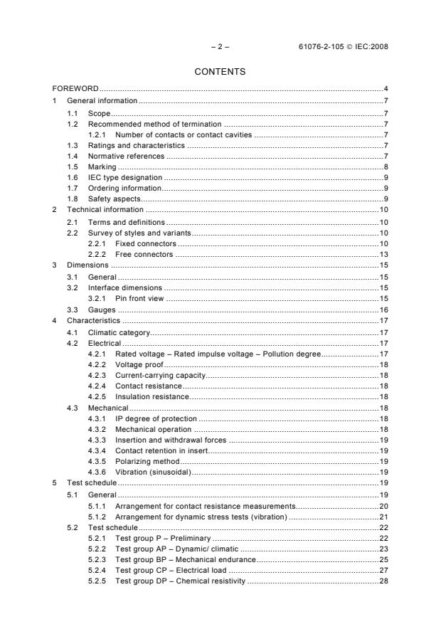
IEC 61076-2-105:2008 - Connectors for electronic equipment - Product requirements - Part 2-105: Circular connectors - Detail specification for M5 connectors with screw-locking Released:7/25/2008
Overview
IEC 61076-2-105:2008 is an international standard published by the International Electrotechnical Commission (IEC) that establishes detailed product requirements for circular M5 connectors with screw-locking mechanisms. These connectors are primarily designed for electronic equipment used in industrial process measurement and control systems. The standard defines the specifications for fixed, rewiring or non-rewiring connectors, as well as free non-rewiring connectors.
This IEC standard ensures consistent product quality, interoperability, and safety in the use of M5 circular connectors across global industries. It covers mechanical, electrical, and climatic characteristics, as well as test procedures to validate compliance.
Key Topics
Connector Types and Styles: Specifies fixed connectors (both male and female contacts) and free connectors with non-rewireable designs. Various mounting options including threaded and mounting orientation details are described.
Dimensions and Interface: Defines precise physical dimensions for connector interface, pin layout, and gauges to ensure compatibility and interchangeability.
Electrical Properties: Covers rated voltage, impulse voltage, current-carrying capacity, contact resistance, insulation resistance, and voltage proof tests based on pollution degree and environmental conditions.
Mechanical Properties: Addresses IP protection ratings, insertion and withdrawal forces, vibration resistance, polarizing methods, and mechanical endurance to guarantee robust and reliable connections in industrial environments.
Climatic and Environmental Conditions: Specifies climatic categories to indicate operating temperature and humidity ranges suitable for the connectors.
Testing and Compliance: Provides a comprehensive test schedule including preliminary tests, dynamic and climatic tests, mechanical endurance, electrical loading, chemical resistivity, and connection method assessments, ensuring compliance with safety and performance requirements.
Marking and Ordering: Describes IEC type designations, marking protocols, and ordering information to facilitate product identification and procurement.
Applications
M5 circular connectors defined in IEC 61076-2-105:2008 are widely used in sectors where reliable, compact, and screw-locked circular connectors are critical for sensor, actuator, and instrumentation interfaces in industrial automation, process control, and measurement systems. Key practical applications include:
- Industrial process automation
- Measurement and control instrumentation
- Factory machinery interfaces
- Robotics and motion control systems
- Harsh environment electrical connections requiring reliable locking and sealing
The connectors’ screw-locking mechanism ensures vibration-resistant and secure connections suitable for demanding industrial conditions. Their compact M5 size makes them ideal for space-constrained electronic assemblies.
Related Standards
IEC 61076-2-105:2008 is part of the broader IEC 61076 series covering product requirements for electronic equipment connectors. Related standards include:
- IEC 61076-2-101: Detail specification for M8 connectors with screw-locking
- IEC 61076-2-104: Specifications for M12 connectors widely used in industrial automation
- IEC 61076-1: General product requirements and terminology for connectors
- ISO/IEC Directives Part 2: Framework followed for drafting IEC standards
Consulting these standards alongside IEC 61076-2-105 provides a comprehensive understanding of connector requirements spanning different sizes and locking mechanisms for industrial applications.
Keywords: IEC 61076-2-105, M5 circular connectors, screw-locking connectors, industrial connectors, process control connectors, electronic equipment connectors, IEC standards, connector dimensions, electrical connector requirements, mechanical endurance connectors, IP rated connectors
Buy Documents
IEC 61076-2-105:2008 - Connectors for electronic equipment - Product requirements - Part 2-105: Circular connectors - Detail specification for M5 connectors with screw-locking Released:7/25/2008
Frequently Asked Questions
IEC 61076-2-105:2008 is a standard published by the International Electrotechnical Commission (IEC). Its full title is "Connectors for electronic equipment - Product requirements - Part 2-105: Circular connectors - Detail specification for M5 connectors with screw-locking". This standard covers: IEC 61076-2-105:2008 describes circular connectors with M5 screw-locking, typically used for industrial process measurement and control. These connectors consist of fixed non-rewireable or rewireable and free connectors non-rewireable.
IEC 61076-2-105:2008 describes circular connectors with M5 screw-locking, typically used for industrial process measurement and control. These connectors consist of fixed non-rewireable or rewireable and free connectors non-rewireable.
IEC 61076-2-105:2008 is classified under the following ICS (International Classification for Standards) categories: 31.220.10 - Plug-and-socket devices. Connectors. The ICS classification helps identify the subject area and facilitates finding related standards.
IEC 61076-2-105:2008 is available in PDF format for immediate download after purchase. The document can be added to your cart and obtained through the secure checkout process. Digital delivery ensures instant access to the complete standard document.
Standards Content (Sample)
IEC 61076-2-105
Edition 1.0 2008-07
INTERNATIONAL
STANDARD
NORME
INTERNATIONALE
Connectors for electronic equipment – Product requirements –
Part 2-105: Circular connectors – Detail specification for M5 connectors with
screw-locking
Connecteurs pour équipements électroniques – Exigences de produit –
Partie 2-105: Connecteurs circulaires – Spécification particulière pour
connecteurs M5 à vis
All rights reserved. Unless otherwise specified, no part of this publication may be reproduced or utilized in any form or by
any means, electronic or mechanical, including photocopying and microfilm, without permission in writing from either IEC or
IEC's member National Committee in the country of the requester.
If you have any questions about IEC copyright or have an enquiry about obtaining additional rights to this publication,
please contact the address below or your local IEC member National Committee for further information.
Droits de reproduction réservés. Sauf indication contraire, aucune partie de cette publication ne peut être reproduite
ni utilisée sous quelque forme que ce soit et par aucun procédé, électronique ou mécanique, y compris la photocopie
et les microfilms, sans l'accord écrit de la CEI ou du Comité national de la CEI du pays du demandeur.
Si vous avez des questions sur le copyright de la CEI ou si vous désirez obtenir des droits supplémentaires sur cette
publication, utilisez les coordonnées ci-après ou contactez le Comité national de la CEI de votre pays de résidence.
IEC Central Office
3, rue de Varembé
CH-1211 Geneva 20
Switzerland
Email: inmail@iec.ch
Web: www.iec.ch
About the IEC
The International Electrotechnical Commission (IEC) is the leading global organization that prepares and publishes
International Standards for all electrical, electronic and related technologies.
About IEC publications
The technical content of IEC publications is kept under constant review by the IEC. Please make sure that you have the
latest edition, a corrigenda or an amendment might have been published.
ƒ Catalogue of IEC publications: www.iec.ch/searchpub
The IEC on-line Catalogue enables you to search by a variety of criteria (reference number, text, technical committee,…).
It also gives information on projects, withdrawn and replaced publications.
ƒ IEC Just Published: www.iec.ch/online_news/justpub
Stay up to date on all new IEC publications. Just Published details twice a month all new publications released. Available
on-line and also by email.
ƒ Electropedia: www.electropedia.org
The world's leading online dictionary of electronic and electrical terms containing more than 20 000 terms and definitions
in English and French, with equivalent terms in additional languages. Also known as the International Electrotechnical
Vocabulary online.
ƒ Customer Service Centre: www.iec.ch/webstore/custserv
If you wish to give us your feedback on this publication or need further assistance, please visit the Customer Service
Centre FAQ or contact us:
Email: csc@iec.ch
Tel.: +41 22 919 02 11
Fax: +41 22 919 03 00
A propos de la CEI
La Commission Electrotechnique Internationale (CEI) est la première organisation mondiale qui élabore et publie des
normes internationales pour tout ce qui a trait à l'électricité, à l'électronique et aux technologies apparentées.
A propos des publications CEI
Le contenu technique des publications de la CEI est constamment revu. Veuillez vous assurer que vous possédez
l’édition la plus récente, un corrigendum ou amendement peut avoir été publié.
ƒ Catalogue des publications de la CEI: www.iec.ch/searchpub/cur_fut-f.htm
Le Catalogue en-ligne de la CEI vous permet d’effectuer des recherches en utilisant différents critères (numéro de référence,
texte, comité d’études,…). Il donne aussi des informations sur les projets et les publications retirées ou remplacées.
ƒ Just Published CEI: www.iec.ch/online_news/justpub
Restez informé sur les nouvelles publications de la CEI. Just Published détaille deux fois par mois les nouvelles
publications parues. Disponible en-ligne et aussi par email.
ƒ Electropedia: www.electropedia.org
Le premier dictionnaire en ligne au monde de termes électroniques et électriques. Il contient plus de 20 000 termes et
définitions en anglais et en français, ainsi que les termes équivalents dans les langues additionnelles. Egalement appelé
Vocabulaire Electrotechnique International en ligne.
ƒ Service Clients: www.iec.ch/webstore/custserv/custserv_entry-f.htm
Si vous désirez nous donner des commentaires sur cette publication ou si vous avez des questions, visitez le FAQ du
Service clients ou contactez-nous:
Email: csc@iec.ch
Tél.: +41 22 919 02 11
Fax: +41 22 919 03 00
IEC 61076-2-105
Edition 1.0 2008-07
INTERNATIONAL
STANDARD
NORME
INTERNATIONALE
Connectors for electronic equipment – Product requirements –
Part 2-105: Circular connectors – Detail specification for M5 connectors with
screw-locking
Connecteurs pour équipements électroniques – Exigences de produit –
Partie 2-105: Connecteurs circulaires – Spécification particulière pour
connecteurs M5 à vis
INTERNATIONAL
ELECTROTECHNICAL
COMMISSION
COMMISSION
ELECTROTECHNIQUE
PRICE CODE
INTERNATIONALE
U
CODE PRIX
ICS 31.220.10 ISBN 2-8318-9936-2
– 2 – 61076-2-105 © IEC:2008
CONTENTS
FOREWORD.4
1 General information.7
1.1 Scope.7
1.2 Recommended method of termination .7
1.2.1 Number of contacts or contact cavities .7
1.3 Ratings and characteristics .7
1.4 Normative references .7
1.5 Marking .8
1.6 IEC type designation .9
1.7 Ordering information.9
1.8 Safety aspects.9
2 Technical information .10
2.1 Terms and definitions .10
2.2 Survey of styles and variants.10
2.2.1 Fixed connectors .10
2.2.2 Free connectors .13
3 Dimensions .15
3.1 General .15
3.2 Interface dimensions .15
3.2.1 Pin front view .15
3.3 Gauges .16
4 Characteristics .17
4.1 Climatic category.17
4.2 Electrical .17
4.2.1 Rated voltage – Rated impulse voltage – Pollution degree.17
4.2.2 Voltage proof.18
4.2.3 Current-carrying capacity.18
4.2.4 Contact resistance.18
4.2.5 Insulation resistance.18
4.3 Mechanical.18
4.3.1 IP degree of protection .18
4.3.2 Mechanical operation .18
4.3.3 Insertion and withdrawal forces .19
4.3.4 Contact retention in insert.19
4.3.5 Polarizing method.19
4.3.6 Vibration (sinusoidal).19
5 Test schedule.19
5.1 General .19
5.1.1 Arrangement for contact resistance measurements.20
5.1.2 Arrangement for dynamic stress tests (vibration) .21
5.2 Test schedule.22
5.2.1 Test group P – Preliminary .22
5.2.2 Test group AP – Dynamic/ climatic .23
5.2.3 Test group BP – Mechanical endurance.25
5.2.4 Test group CP – Electrical load .27
5.2.5 Test group DP – Chemical resistivity .28
61076-2-105 © IEC:2008 – 3 –
5.2.6 Test group EP – Connection method tests .28
Annex A (informative) Diameter of the female connector body .29
Bibliography.30
Figure 1 – Tube insert, male contacts, mounting without thread .11
Figure 2 – Fixed connector, male contacts, mounting with thread M5 × 0,5, with wire
ends, single hole mounting M5 × 0,5, mounting orientation .11
Figure 3 – Fixed connector, male contacts, mounting with thread M5 × 0,5, with wire
ends, single hole rear mounting, thread M5 × 0,5, mounting orientation .12
Figure 4 – Fixed connector, female contacts, mounting with thread M5 × 0,5, with wire
ends, single mounting, thread M5 × 0,5, mounting orientation .12
Figure 5 – Fixed connector, female contacts, mounting with thread M5 × 0,5, with wire
ends, single hole rear mounting, thread M5 × 0,5, mounting orientation .13
Figure 6 – Non-rewireable connector, male contacts, straight version, with locking nut .13
Figure 7 – Non-rewireable connector, male contacts, right angled version, with locking nut .14
Figure 8 – Non-rewireable connector, female contacts, straight version, with locking nut .14
Figure 9 – Non-rewireable connector, female contacts, right angled version, with
locking nut .14
Figure 10 – Pin front view .15
Figure 11 – Contact position front view .16
Figure 12 – Gauge dimensions .16
Figure 13 – Contact resistance arrangement.20
Figure 14 – Dynamic stress test arrangement .21
Figure A.1 – Diameter of the female connector body.29
Table 1 – Styles of fixed connectors type A.10
Table 2 – Styles of free connectors.13
Table 3 – Gauges .17
Table 4 – Climatic category .17
Table 5 – Rated voltage – Rated impulse voltage – Pollution degree .17
Table 6 – Voltage proof.18
Table 7 – Number of mechanical operations .19
Table 8 – Insertion and withdrawal forces .19
Table 9 – Number of test specimens .20
Table 10 – Test group P .22
Table 11 – Test group AP .23
Table 12 – Test group BP .25
Table 13 – Test group CP .27
Table 14 – Test group DP .28
Table 15 – Test group EP .28
– 4 – 61076-2-105 © IEC:2008
INTERNATIONAL ELECTROTECHNICAL COMMISSION
____________
CONNECTORS FOR ELECTRONIC EQUIPMENT –
PRODUCT REQUIREMENTS –
Part 2-105: Circular connectors –
Detail specification for M5 connectors with screw-locking
FOREWORD
1) The International Electrotechnical Commission (IEC) is a worldwide organization for standardization comprising
all national electrotechnical committees (IEC National Committees). The object of IEC is to promote
international co-operation on all questions concerning standardization in the electrical and electronic fields. To
this end and in addition to other activities, IEC publishes International Standards, Technical Specifications,
Technical Reports, and Guides (hereafter referred to as “IEC Publication(s)”). Their preparation is entrusted to
technical committees; any IEC National Committee interested in the subject dealt with may participate in this
preparatory work. International, governmental and non-governmental organizations liaising with the IEC also
participate in this preparation. IEC collaborates closely with the International Organization for Standardization
(ISO) in accordance with conditions determined by agreement between the two organizations.
2) The formal decisions or agreements of IEC on technical matters express, as nearly as possible, an international
consensus of opinion on the relevant subjects since each technical committee has representation from all
interested IEC National Committees.
3) IEC Publications have the form of recommendations for international use and are accepted by IEC National
Committees in that sense. While all reasonable efforts are made to ensure that the technical content of IEC
Publications is accurate, IEC cannot be held responsible for the way in which they are used or for any
misinterpretation by any end user.
4) In order to promote international uniformity, IEC National Committees undertake to apply IEC Publications
transparently to the maximum extent possible in their national and regional publications. Any divergence
between any IEC Publication and the corresponding national or regional publication shall be clearly indicated in
the latter.
5) IEC provides no marking procedure to indicate its approval and cannot be rendered responsible for any
equipment declared to be in conformity with an IEC Publication.
6) All users should ensure that they have the latest edition of this publication.
7) No liability shall attach to IEC or its directors, employees, servants or agents including individual experts and
members of its technical committees and IEC National Committees for any personal injury, property damage or
other damage of any nature whatsoever, whether direct or indirect, or for costs (including legal fees) and
expenses arising out of the publication, use of, or reliance upon, this IEC Publication or any other IEC
Publications.
8) Attention is drawn to the Normative references cited in this publication. Use of the referenced publications is
indispensable for the correct application of this publication.
9) Attention is drawn to the possibility that some of the elements of this IEC Publication may be the subject of
patent rights. IEC shall not be held responsible for identifying any or all such patent rights.
International Standard IEC 61076-2-105 has been prepared by subcommittee 48B:
Connectors, of technical committee 48: Electromechanical components and mechanical
structures for electronic equipment.
The text of this standard is based on the following documents:
FDIS Report on voting
48B/1909/FDIS 48B/1928/RVD
Full information on the voting for the approval of this standard can be found in the report on
voting indicated in the above table.
This publication has been drafted in accordance with the ISO/IEC Directives, Part 2.
A list of all parts of the IEC 61076 series, under the general title Connectors for electronic
equipment – Product requirements, can be found on the IEC website.
61076-2-105 © IEC:2008 – 5 –
The committee has decided that the contents of this publication will remain unchanged until
the maintenance result date indicated on the IEC web site under "http://webstore.iec.ch" in
the data related to the specific publication. At this date, the publication will be
• reconfirmed;
• withdrawn;
• replaced by a revised edition; or
• amended.
– 6 – 61076-2-105 © IEC:2008
INTERNATIONAL ELECTROTECHNICAL COMMISSION IEC 61076-2-105
IEC SC 48B – Connectors
ELECTRONIC COMPONENTS
DETAIL SPECIFICATION in accordance with
IEC 61076-1:2006
Circular connectors
M5 3 to 4 way
Male and female contacts
Non-rewireable (fixed connector
could also be rewirable)
Free cable connectors
Straight and right angle connectors
Fixed connectors
Single hole mounting
IEC 1248/08
61076-2-105 © IEC:2008 – 7 –
CONNECTORS FOR ELECTRONIC EQUIPMENT –
PRODUCT REQUIREMENTS –
Part 2-105: Circular connectors –
Detail specification for M5 connectors with screw-locking
1 General information
Throughout this standard dimensions are in mm.
1.1 Scope
This part of IEC 61076 describes circular connectors with M5 screw-locking, typically used for
industrial process measurement and control.
NOTE M5 is the dimension of the thread of the screw locking mechanism of these circular connectors.
These connectors consist of fixed non-rewirable or rewirable and free connectors non-
rewireable.
Male connectors have round contacts ∅ 0,48 mm.
1.2 Recommended method of termination
The contact terminations shall be of the following types: screw, crimp, insulation piercing,
insulation displacement, press-in or solder.
1.2.1 Number of contacts or contact cavities
3 and 4 contacts.
1.3 Ratings and characteristics
Rated voltage 3 contacts 60 V d.c. or a.c.
4 contacts 60 V d.c. or a.c.
Current rating 3 contacts 1 A
4 contacts 1 A
Insulation resistance : 10 Ω min.
Climatic category : see 4.1 Table 4
Contact spacing : see Clause 3
1.4 Normative references
The following referenced documents are indispensable for the application of this document.
For dated references, only the edition cited applies. For undated references, the latest edition
of the referenced document (including any amendments) applies.
IEC 60050-581, International Electrotechnical Vocabulary – Part 581: Electromechanical
components for electronic equipment
– 8 – 61076-2-105 © IEC:2008
IEC 60068-1:1988, Environmental testing – Part 1: General and guidance
Amendment 1 (1992)
IEC 60068-2-60:1995, Environmental testing – Part 2: Tests – Test Ke: Flowing mixed gas
corrosion test
IEC 60352 (all parts), Solderless connections
IEC 60512 (all parts), Connectors for electronic equipment – Tests and measurements
IEC 60529:1989, Degrees of protection provided by enclosures (IP Code)
Amendment 1 (1999)
IEC 60664-1:2007, Insulation coordination for equipment within low-voltage systems – Part 1:
Principles, requirements and tests
IEC 60998-2-1:2002, Connecting devices for low-voltage circuits for household and similar
purposes – Part 2-1: Particular requirements for connecting devices as separate entities with
screw-type clamping units
IEC 60999 (all parts), Connecting devices – Electrical copper conductors – Safety
requirements for screw-type and screwless-type clamping units
IEC 61076-1:2006, Connectors for electronic equipment – Product requirements – Part 1:
Generic Specification
IEC 61984:2001, Connectors – Safety requirements and tests
ISO 1302:2002, Geometrical Product Specifications (GPS) – Indication of surface texture in
technical product documentation
1.5 Marking
The marking of the connector and the package shall be in accordance with 2.7 of
IEC 61076-1.
61076-2-105 © IEC:2008 – 9 –
1.6 IEC type designation
IEC 61076-2-105
L LNNN L LN L
Reference to this specification Letter denoting coding
devices
Not applicable
Letter denoting the connector
style
See Tables 1 and 2 Number denoting contact
finish
Gold 1
Silver 2
Tin 3
Other types 4
Number of contacts Letter denoting style of
termination
without PE contact 003
004 Screw A
Crimp C
Insulation displacement I
Insulation piercing P
Press-in R
Solder contact S
Letter denoting style of locking nut
or snap-locking
Knurled ring G
Hexagonal ring H
NOTE “L” stands for letter, “N” stands for number.
1.7 Ordering information
For ordering connectors to this standard, the type designation described in 1.6 shall be used.
Example: MF 004 – GS1
Free connector, non-rewireable, right angled version, 4 ways, with knurled ring, female solder
termination contacts, contact area gold finish.
1.8 Safety aspects
For safety aspects, IEC 61984 shall be considered unless otherwise specified.
– 10 – 61076-2-105 © IEC:2008
2 Technical information
Dimensions in mm.
2.1 Terms and definitions
For the purposes of this part of IEC 61076, terms and definitions from IEC 60050-581,
together with the following, apply.
2.1.1
mounting orientation
circular mounting position of the connector in relation to the polarization of the mating
interface.
NOTE Where the free connector has an angled cable entry (as opposed to an in-line cable entry), the angle
between the cable entry and the polarization keyway should be specified.
2.2 Survey of styles and variants
For all connector styles with cables, the length L of the cable shall be agreed between
manufacturer and user.
For interface dimensions see 3.2.
The interface dimensions of the female styles shall be chosen according to the common
characteristics of the male styles.
For reliable intermateability, the dimensions of the female connector body as detailed in
Annex A have to be met.
2.2.1 Fixed connectors
Table 1 – Styles of fixed connectors type A
Style Description
AM Tube insert, male contacts, mounting without thread
GM Fixed connector, male contacts, mounting with thread M5 × 0,5, with wire ends, single hole mounting thread
M5 × 0,5, mounting orientation
PM Fixed connector, male contacts, mounting with thread M5 × 0,5, with wire ends, single hole rear mounting
thread M5 × 0,5, mounting orientation
GF
Fixed connector, female contacts, mounting with thread M5 × 0,5, with wire ends, single hole mounting,
thread M5 × 0,5, mounting orientation
PF Fixed connector, female contacts, mounting with thread M5 × 0,5, with wire ends, single hole rear mounting,
thread M5 × 0,5, mounting orientation
61076-2-105 © IEC:2008 – 11 –
2.2.1.1 Style AM
10,7
Mounting hole in tube
∅3,75 H7
0,7
8,2
IEC 1249/08
Figure 1 – Tube insert, male contacts, mounting without thread
2.2.1.2 Style GM
12 max. L = length of wire ends
∅7,8 max.
6,7 max.
Position free
2 max.
Sealing
to flange
Fixing nut IEC 1250/08
Figure 2 – Fixed connector, male contacts, mounting with thread M5 × 0,5, with wire
ends, single hole mounting M5 × 0,5, mounting orientation
∅4,3
M5 × 0,5
∅ according to mounting hole
– 12 – 61076-2-105 © IEC:2008
2.2.1.3 Style PM
L = length of wire ends
12 max.
10 max.
∅7,8 max.
2 max.
Position free
to flange
Fixing nut Sealing
IEC 1251/08
Figure 3 – Fixed connector, male contacts, mounting with thread M5 × 0,5, with wire
ends, single hole rear mounting, thread M5 × 0,5, mounting orientation
2.2.1.4 Style GF
L = length of wire ends
12 max.
∅7,8 max.
5,7 max.
Position free
Fixing nut
to flange
Sealing
2 max.
IEC 1252/08
Figure 4 – Fixed connector, female contacts, mounting with thread M5 × 0,5, with wire
ends, single mounting, thread M5 × 0,5, mounting orientation
M5 × 0,5
M5 × 0,5
61076-2-105 © IEC:2008 – 13 –
2.2.1.5 Style PF
L = length of wire ends
12 max.
9,8 max.
∅9,8 max.
2,5 max.
Position free
to flange
Fixing nut
Sealing Sealing
IEC 1253/08
Figure 5 – Fixed connector, female contacts, mounting with thread M5 × 0,5, with wire
ends, single hole rear mounting, thread M5 × 0,5, mounting orientation
2.2.2 Free connectors
Table 2 – Styles of free connectors
Style Description
a
LM Non-rewireable connector, male contacts, straight version, with locking nut
a
MM Non-rewireable connector, male contacts, right angled version, with locking nut
a
LF Non-rewireable connector, female contacts, straight version, with locking nut
a
MF Non-rewireable connector, female contacts, right angled version, with locking nut
a
Knurled ring or hexagonal ring upon agreement.
2.2.2.1 Style LM
L = length of cable
38 max.
IEC 1254/08
Figure 6 – Non-rewireable connector, male contacts, straight version, with locking nut
M7 × 0,75
∅6,5 max.
– 14 – 61076-2-105 © IEC:2008
2.2.2.2 Style MM
L = length of cable
3,5 max. 25 max.
IEC 1255/08
Figure 7 – Non-rewireable connector, male contacts,
right angled version, with locking nut
2.2.2.3 Style LF
L = length of cable
35 max.
Sealing
IEC 1256/08
Figure 8 – Non-rewireable connector, female contacts,
straight version, with locking nut
2.2.2.4 Style MF
L = length of cable
3,5 max. 25 max.
Sealing
∅6,5 max.
IEC 1257/08
Figure 9 – Non-rewireable connector, female contacts,
right angled version, with locking nut
∅6,5 max.
22 max.
25 max.
61076-2-105 © IEC:2008 – 15 –
3 Dimensions
3.1 General
All dimensions in millimeters are original. Drawings are shown in the first angle projection.
The shape of the connectors may deviate from those given in the following drawings as long
as the specified dimensions are not influenced.
For connector dimensions see drawings item 2.2.
Missing dimensions shall be chosen according to common characteristics and intended use.
3.2 Interface dimensions
3.2.1 Pin front view
4,2 min.
3,5 min.
1,5 max.
4× ∅0,48
–0,03
0,2 × 45° max.
A
∅0,1
4 way
+0,1
R0,2
1,25
3,0 ± 0,1
+0,1
+0,2
1,0 4,5
+0,1
3,2 Sealing surface
A
3×
∅0,48
–0,03
∅0,1 A
3 way
1,25
+0,1
3,2
A IEC 1258/08
Figure 10 – Pin front view
1,25 1,25
1,1
–0,1
(90°)
∅4,25
–0,05
M5 × 0,5
– 16 – 61076-2-105 © IEC:2008
Contact position front view
Male Female
4 3 3 4
4 way
1 2 2 1
4 3 3 4
3 way
IEC 1259/08
NOTE Unloaded cavities of the female connector may be open.
Figure 11 – Contact position front view
If legible, the contact marking shall be on the termination side of the connector insert as long
as the size of the component allows the placement there.
3.3 Gauges
Sizing gauges and retention force gauges
Material: tool steel, hardened
= Surface (clean and free of grease)
roughness according to ISO 1302: Ra = 0,25 μm max
0,15 μm min
R
l
IEC 2378/03
Figure 12 – Gauge dimensions
a
61076-2-105 © IEC:2008 – 17 –
Table 3 – Gauges
Gauge Mass Application ∅ a l min Nominal
g mm
mm pin ∅
P11 - Sizing 0,51 10
+0,03
0,48
P12 20 Retention force 0,48 10
4 Characteristics
4.1 Climatic category
Conditions: IEC 60068-1
Table 4 – Climatic category
Category temperature Damp heat steady state
Climatic
Days
Lower Upper Temperature Rel. humidity
category
°C °C °C %
25/85/21 –25 +85 40 93 21
4.2 Electrical
4.2.1 Rated voltage – Rated impulse voltage – Pollution degree
Conditions: IEC 60664-1
The permissible rated voltage depends on the application or specified safety requirement.
Reductions in creepage or clearance distances may occur due to the printed board or wiring
used and shall be duly taken into account.
Table 5 – Rated voltage – Rated impulse voltage –
Pollution degree
Rated Rated impulse Pollution
No. of ways a
voltage voltage degree
according to 3.2.1
V kV
3 60 1,5 3
4 60 1,5 3
a
Only in mated and locked condition.
– 18 – 61076-2-105 © IEC:2008
4.2.2 Voltage proof
Conditions: IEC 60512, test 4a
Standard atmospheric conditions
Mated connectors
Table 6 – Voltage proof
Voltage in kV
Between contacts
Between contacts and metal-housing
No. of ways
r.m.s. withstand voltage
according to 3.2.1
Fixed connectors Free connectors Fixed connectors Free connectors
3 0,90 0,90 0,90 0,90
4 0,90 0,90 0,90 0,90
4.2.3 Current-carrying capacity
Conditions: IEC 60512, test 5d
All contacts
Values at 40 °C
3 way = 1 A
4 way = 1 A
4.2.4 Contact resistance
Conditions: IEC 60512, test 2a
Standard atmospheric conditions
connecting points see 5.1.1
4.2.5 Insulation resistance
Conditions: IEC 60512, test 3a, method A
Standard atmospheric conditions
Test voltage 500 V ± 15 V d.c.
4.3 Mechanical
4.3.1 IP degree of protection
IP65/IP67 according to IEC 60529 connectors in mated and locked position. IP68 on
agreement between manufacturer and user.
4.3.2 Mechanical operation
Conditions: IEC 60512, test 9a
Standard atmospheric conditions
Max. speed of operations = 10 mm/s
Rest: 30 s, unmated
61076-2-105 © IEC:2008 – 19 –
Table 7 – Number of mechanical operations
Contact finish Mechanical operations
Gold 100
Silver 50
Tin 20
a
Other types
a
Other mating cycles are upon agreement between manufacturer and user.
4.3.3 Insertion and withdrawal forces
Conditions: IEC 60512, test 13b
Standard atmospheric conditions
Max. speed = 10 mm/s
Table 8 – Insertion and withdrawal forces
Force in N
Number of poles Total insertion force Total withdrawal force
3 max. 8 max. 6
4 max. 8 max. 6
4.3.4 Contact retention in insert
Not applicable.
For removable crimp type contacts, the introduction of an appropriate requirement is under
consideration.
4.3.5 Polarizing method
Conditions: IEC 60512, test 13e
Insertion force: to be defined (tbd) min.
4.3.6 Vibration (sinusoidal)
Conditions: IEC 60512, test 6d
Standard atmospheric conditions
Connectors in mated and locked position
The fixed and free connector shall be rigidly installed in a suitable fixture as
specified in 5.1.2.
Vibration severity: 10 Hz to 500 Hz and 0,35 mm or 50 mm/s
5 Test schedule
5.1 General
This test schedule shows the tests and the order in which they shall be carried out as well as
the requirements to be met.
Unless otherwise specified, all tests shall be carried out under standard atmospheric
conditions for testing as specified in IEC 60068-1, as directed by the applicable part of
IEC 60512.
– 20 – 61076-2-105 © IEC:2008
Unless otherwise specified, mated and locked sets of connectors shall be tested. Care shall
be taken to keep a particular combination of connectors together during the complete test
sequence, i.e. when unmating is necessary for a certain test, the same connector styles as
before shall be mated for the subsequent tests.
In the following, a mated and locked sets of connector styles is called a specimen.
When the initial tests P have been completed, the specimens are divided in the 4 test groups
AP, BP, CP and DP. In addition, 20 single contacts are used for EP.
Before testing commences, the connectors shall be stored for at least 24 hours in the non-
engaged state under standard atmospheric conditions as per IEC 60068-1.
The necessary specimens are stated in Table 9.
Table 9 – Number of test specimens
Test group
P AP BP CP DP EP
No. of 12 3 3 3 3 20 single
specimen contacts
5.1.1 Arrangement for contact resistance measurements
Conditions: see 4.2.4
The measurement of contact resistance shall be carried out on the number of contacts
specified. Any subsequent measurements of contact resistance shall be made on the same
contacts.
Connection points
40 40
Cable Cable
Free connector Fixed connector
IEC 1260/08
Figure 13 – Contact resistance arrangement
61076-2-105 © IEC:2008 – 21 –
5.1.2 Arrangement for dynamic stress tests (vibration)
Conditions: see 4.3.6
Fixed connector
25 max. 25 max.
Free connector
Cable clamp
Cable clamp
Fixture
Mounting panel
IEC 1261/08
Fixed connector
25 max.
Free connector
Cable clamp
Cable clamp
Fixture Mounting panel
IEC 1262/08
Connector clamp
25 max. 25 max.
Free male connector Free female connector
Cable clamp Cable clamp
Fixture
IEC 1263/08
Figure 14 – Dynamic stress test arrangement
25 max.
– 22 – 61076-2-105 © IEC:2008
5.2 Test schedule
5.2.1 Test group P – Preliminary
All specimens shall be subject to the following tests.
Table 10 – Test group P
Test Test Measurement to be Requirements
phase performed
Title IEC 60512 Severity or Title IEC 60512 All connector styles
Test No. condition of test Test No.
P1 General 1 Unmated Visual 1a There shall be no defect
examination connectors examination that would impair
normal
operation
Dimensional 1b The dimensions shall
examination comply with those
specified in 2.2 and 3
P2 Polarizing 13e See 4.3.5 Not applicable, see test
method group AP, test phase
AP9 (see Table 11).
P3 Connection points Contact 2a initial value
according to 5.1.1 all resistance – 10 mΩ max.
contacts per specimens Millivolt
level
method
P4 Test voltage Insulation 3a
10 Ω min.
resistance
500 V ± 15 V d.c.
Method A
P5 Contact/ Voltage 4a According to 4.2.2
contact same proof
measuring points as for
P4
The specimen shall be divided into five groups. All connectors in each group shall undergo
the tests specified for the relevant group.
61076-2-105 © IEC:2008 – 23 –
5.2.2 Test group AP – Dynamic/ climatic
Table 11 – Test group AP
Test Test Measurement to be Requirements
phase performed
Title IEC 60512 Severity or Title IEC 60512 All connector styles
Test No. condition of test Test No.
AP1 See 4.3.3 Insertion 13b Requirements see 4.3.3
and
withdrawal
forces
AP2 Gauge Female contacts only 3 Engaging 16e See 3.3
retention contacts/ and
force specimen sizing and separating
retention force gauge forces
see 3.3
AP3 Vibration 6d 10 Hz–500 Hz 0,35 mm Contact 2e Duration of disturbance
or 50 mm/s disturbance
1 μs max.
Sweep cycles: 10
Contact 2a Rise in relation to initial
Full duration: 6 h
resistance – values 15 mΩ max.
Millivolt
level
method
Visual 1a There shall be no
examination defect that would impair
normal operation
Arrangement according
AP4 Shock 6c Contact 2e Duration of disturbance
to 5.1.2
disturbance 1 μs max.
Half sine
shock acceleration
490 m/s (50 g) Contact 2a Rise in relation to initial
resistance – values 15 mΩ max.
Duration of impact:
Millivolt
11 ms
level
method
Visual 1a There shall be no
examination defect that would impair
normal operation
AP5 Rapid 11d –25 °C to 85 °C, Contact 2a Rise in relation to initial
change of t = 30 min, 5 cycles resistance-
values 15 mΩ max.
temperature Millivolt
level
method
Insulation 3a
10 Ω min.
resistance
Voltage 4a According to 4.2.2
proof
Visual 1a There shall be no
examination defect that would impair
normal operation
AP6 Climatic 11a
sequence
AP6.1 Dry heat 11i Temp.: 85 °C Insulation 3a
10 Ω min.
Duration: 16 h resistance
at high
temperature
– 24 – 61076-2-105 © IEC:2008
Table 11 (continued)
Test Test Measurement Requirements
phase to be performed
Title IEC 60512 Severity or Title IEC 60512
Test No. condition of test Test No.
AP6.2 Damp heat, 11m Method Db Visual 1a There shall be no
cyclic, first Temp.: 40 °C examination defect
cycle Recovery time: 2 h that would impair
normal
operation
AP6.3 Cold 11j Temp.: –25 °C Visual 1a There shall be no
Duration: 2 h examination defect
Recovery time: 2 h that would impair
normal
operation
AP6.4 Damp heat, 11m Conditions according to Contact 2a Rise in relation to initial
cyclic, AP6.2 resistance – values
remaining 5 cycles Millivolt
15 mΩ max.
cycles Recovery time: 2 h level
method
Insulation 3a
10 Ω min.
resistance
Voltage 4a According to 4.2.2
proof
Insertion 13b See 4.3.3
and
withdrawal
forces
Visual 1a There shall be no
examination defect
that would impair
normal
operation
AP7 Impacting 14g
dust and
water
AP7.1 IP code See IEC 60529 IEC 60529 No leakage on contacts
second Test 14.2.5
characteris- and Test
tic numeral 14.2.7
AP7.2 IP code first Dust IP6X Test 6 IEC 60529 IP6X no deposit of dust
a
characteris- Table 7 Test 6 on contacts
tic numeral Table 7
AP7.3 Contact 2 Rise in relation to initial
resistance –
values 15 mΩ max.
Millivolt
2b
level
Insulation 3a 10 Ω min.
resistance
Voltage 4a According to 4.2.2
proof
Insertion 13b See 4.3.3
and
withdrawal
forces
61076-2-105 © IEC:2008 – 25 –
Table 11 (continued)
Test Test Measurement Requirements
phase to be performed
Title IEC 60512 Severity or Title IEC 60512
Test No. condition of test Test No.
AP8 Visual 1a There shall be no
examination defect
that would impair
normal
operation
AP9 Polarizing 13e See 4.3.5 It shall be possible to
method correctly align and
mate the appropriate
mating connectors.
It shall not be possible
to mate the connectors
in any other than the
correct manner
a
It is allowed to perform AP7.2 with an additional specimen, extending the total number of specimen by 1.
5.2.3 Test group BP – Mechanical endurance
Table 12 – Test group BP
Test Test Measurement Requirements
phase to be performed
Title IEC 60512 Severity or Title IEC 60512
Test No. condition of test Test No.
BP1 Female contacts only 3 Gauge 16e See 3.3
contacts/specimen retention
sizing and retention force
force gauge see 3.3
BP2 Mechanical 9a Speed 10 mm/s max.
operation Rest 30 s (unmated)
(half of the Operations see 4.3.2
specified Speed: 10 mm/s max.
number of Rest time: 30 s
operations) (unmated)
Contact 2a Rise in relation to
resistance – initial values
Millivolt 15 mΩ max.
level
method
Visual 1a There shall be no
examination defect
that would impair
normal
operation
BP3 Climatic test
BP3.1 Corrosion 11g Flowing mixed gas Contact 2a Rise in relation to
industrial corrosion – 4 days, test resistance – initial values
atmosphere method 4 according Millivolt
15 mΩ max.
IEC 60068-2-60 level
method
– 26 – 61076-2-105 © IEC:2008
Table 12 (continued)
Test Test Measurement Requirements
phase to be performed
Title IEC 60512 Severity or Title IEC 60512
Test No. condition of test Test No.
BP4 Mechanical 9a See BP2 Contact 2a Rise in relation to
operation resistance – initial values 15 mΩ
(remaining Millivolt
max.
half of level
specified method
number of
Insulation 3a
10 Ω min.
operations)
resistance
Voltage 4a According to 4.2.2
proof
Unmated connectors Visual 1a There shall be no
examination defect
that would impair
normal
operation
BP5.1 IP code See IEC 60529 IEC 60529 No leakage on
second Test 14.2.5 contacts
characteris- and Test
tic numeral 14.2.7
BP5.2 Insulation 3a 10 Ω min.
resistance
Voltage 4a According to 4.2.2
proof
BP6 Insertion 13b Requirements see
and 4.3.3
withdrawal
forces
BP7 Female contacts only 3 Gauge 16e See 3.3
contacts/specimen retention
sizing and retention force
force gauge see 3.3
61076-2-105 © IEC:2008 – 27 –
5.2.4 Test group CP – Electrical load
Table 13 – Test group CP
Test Test Measurement Requirements
phase to be performed
Title IEC 60512 Severity or Title IEC 60512 All connector styles
Test No. condition of test Test No.
CP1 Rapid 11d –25 °C to 85 °C, Contact 2a Rise in relation to initial
change of t = 1 h, 5 cycles resistance –
values 15 mΩ max.
temperature Millivolt
level
method
Insulation 3a 10 Ω min.
resistance
Voltage 4a According to 4.2.2
proof
CP2 Mechanical 9a See BP2
operation
CP3 Electrical 9b Duration: 1 000 h Contact 2a Rise in relation to initial
load and Amb. Temp.: 40 °C resistance –
values 15 mΩ max.
temperature Current load according Millivolt
to
...