


IEC 62848-1:2016
(Main)Railway applications - DC surge arresters and voltage limiting devices - Part 1: Metal-oxide surge arresters without gaps
Railway applications - DC surge arresters and voltage limiting devices - Part 1: Metal-oxide surge arresters without gaps
IEC 62848-1:2016 applies to non-linear metal-oxide surge arresters without gaps for both on board and fixed installations, designed to limit voltage surges on DC systems specified in IEC 60850 with nominal voltage up to 3 kV.
Applications ferroviaires - Parafoudres et appareils limiteurs de tension pour réseaux à courant continu - Partie 1: Parafoudres à oxyde métallique sans éclateur
L'IEC 62848-1:2016 s'applique aux parafoudres à oxyde métallique non linéaires sans éclateurs pour des installations fixes ou embarquées, conçus pour limiter les surtensions dans les réseaux à courant continu spécifiés dans l'IEC 60850, d'une tension nominale allant jusqu'à 3 kV.
General Information
- Status
- Published
- Publication Date
- 14-Jun-2016
- Technical Committee
- TC 9 - Electrical equipment and systems for railways
- Drafting Committee
- PT 62848-1 - TC 9/PT 62848-1
- Current Stage
- PPUB - Publication issued
- Start Date
- 15-Jun-2016
- Completion Date
- 31-Jul-2016
Overview
IEC 62848-1:2016 is an international standard developed by the International Electrotechnical Commission (IEC) that specifies requirements for metal-oxide surge arresters without gaps used in railway applications. This standard covers both on-board and fixed installations designed to limit voltage surges on DC railway systems with nominal voltages up to 3 kV, as specified in IEC 60850. By defining performance criteria, testing methods, and classification, IEC 62848-1 ensures the safety, reliability, and durability of surge arresters essential for protecting railway electrical equipment from transient overvoltages.
Key Topics
- Scope and Application: Applies to non-linear metal-oxide surge arresters without gaps for DC railway systems up to 3 kV, suitable for onboard and fixed installation use.
- Arrester Characteristics: Defines marking, insulation withstand, residual voltage, internal partial discharges, current distribution, operating duty, and short circuit behavior.
- Testing Procedures:
- Insulation withstand tests including wet tests, lightning impulse, and DC voltage withstand.
- Residual voltage testing under steep current impulse, lightning impulse, and switching impulse.
- Charge transfer and operating duty tests to simulate actual service conditions and accelerated aging.
- Short circuit impact tests to verify mechanical and electrical robustness.
- Environmental and mechanical testing such as weather aging, temperature cycling, shock, vibration, bending moment, and seal leak rate evaluations.
- Classification and Requirements: Surge arresters are categorized by their protective characteristics and nominal discharge currents, ensuring proper selection for different railway system needs.
Applications
IEC 62848-1:2016 is essential for manufacturers, railway operators, and electrical engineers responsible for the design, installation, and maintenance of DC surge protection devices in railway infrastructures. Key applications include:
- Onboard Rolling Stock: Protecting electrical circuits and sensitive equipment from transient voltages generated during switching operations or lightning strikes.
- Fixed Installations: Safeguarding substations, signaling systems, and power supply components critical to railway operation.
- Voltage Surge Limiting: Providing reliable and fast voltage surge limitation without gaps to enhance system durability and continuity.
- Maintenance and Testing: Establishing routine testing procedures to ensure surge arresters retain performance over operational life, improving safety and minimizing downtime.
Related Standards
- IEC 60850: Specifies parameters for DC power supply systems used in electric traction, providing context for surge arrester voltage ratings.
- IEC 60137: Connectors for railway signaling and power supply protection.
- IEC 60071: Insulation coordination principles relevant for surge arrester design and application.
- IEC 60060: High-voltage test techniques for validating testing methods referenced in IEC 62848-1.
- EN 50155: Standard for electronic equipment on rolling stock, complementary to surge protection requirements.
By adhering to IEC 62848-1, railway electrification and signaling systems benefit from standardized, high-quality surge protection, ensuring operational reliability, equipment safety, and compliance with international best practices in railway electrical standards.
Keywords: IEC 62848-1, metal-oxide surge arrester, railway surge protection, DC surge arresters, voltage limiting devices, railway electrical standards, IEC 60850, transient overvoltage protection, railway electrical safety, surge arrester testing, high voltage DC systems.
Get Certified
Connect with accredited certification bodies for this standard

Bureau Veritas Railway Certification
Railway and transportation certification.

Deutsch Quality Systems (India) Pvt. Ltd. (DQS India)
Subsidiary of DQS Holding GmbH, founding member of IQNet. CDSCO Notified Body.

Excellence Ireland Quality Association (EIQA)
Irish quality certification organization.
Sponsored listings
Frequently Asked Questions
IEC 62848-1:2016 is a standard published by the International Electrotechnical Commission (IEC). Its full title is "Railway applications - DC surge arresters and voltage limiting devices - Part 1: Metal-oxide surge arresters without gaps". This standard covers: IEC 62848-1:2016 applies to non-linear metal-oxide surge arresters without gaps for both on board and fixed installations, designed to limit voltage surges on DC systems specified in IEC 60850 with nominal voltage up to 3 kV.
IEC 62848-1:2016 applies to non-linear metal-oxide surge arresters without gaps for both on board and fixed installations, designed to limit voltage surges on DC systems specified in IEC 60850 with nominal voltage up to 3 kV.
IEC 62848-1:2016 is classified under the following ICS (International Classification for Standards) categories: 45.060.01 - Railway rolling stock in general. The ICS classification helps identify the subject area and facilitates finding related standards.
IEC 62848-1:2016 is available in PDF format for immediate download after purchase. The document can be added to your cart and obtained through the secure checkout process. Digital delivery ensures instant access to the complete standard document.
Standards Content (Sample)
IEC 62848-1 ®
Edition 1.0 2016-06
INTERNATIONAL
STANDARD
NORME
INTERNATIONALE
Railway applications – DC surge arresters and voltage limiting devices –
Part 1: Metal-oxide surge arresters without gaps
Applications ferroviaires – Parafoudres et appareils limiteurs de tension pour
réseaux à courant continu –
Partie 1: Parafoudres à oxyde métallique sans éclateur
All rights reserved. Unless otherwise specified, no part of this publication may be reproduced or utilized in any form
or by any means, electronic or mechanical, including photocopying and microfilm, without permission in writing from
either IEC or IEC's member National Committee in the country of the requester. If you have any questions about IEC
copyright or have an enquiry about obtaining additional rights to this publication, please contact the address below or
your local IEC member National Committee for further information.
Droits de reproduction réservés. Sauf indication contraire, aucune partie de cette publication ne peut être reproduite
ni utilisée sous quelque forme que ce soit et par aucun procédé, électronique ou mécanique, y compris la photocopie
et les microfilms, sans l'accord écrit de l'IEC ou du Comité national de l'IEC du pays du demandeur. Si vous avez des
questions sur le copyright de l'IEC ou si vous désirez obtenir des droits supplémentaires sur cette publication, utilisez
les coordonnées ci-après ou contactez le Comité national de l'IEC de votre pays de résidence.
IEC Central Office Tel.: +41 22 919 02 11
3, rue de Varembé Fax: +41 22 919 03 00
CH-1211 Geneva 20 info@iec.ch
Switzerland www.iec.ch
About the IEC
The International Electrotechnical Commission (IEC) is the leading global organization that prepares and publishes
International Standards for all electrical, electronic and related technologies.
About IEC publications
The technical content of IEC publications is kept under constant review by the IEC. Please make sure that you have the
latest edition, a corrigenda or an amendment might have been published.
IEC Catalogue - webstore.iec.ch/catalogue Electropedia - www.electropedia.org
The stand-alone application for consulting the entire The world's leading online dictionary of electronic and
bibliographical information on IEC International Standards, electrical terms containing 20 000 terms and definitions in
Technical Specifications, Technical Reports and other English and French, with equivalent terms in 15 additional
documents. Available for PC, Mac OS, Android Tablets and languages. Also known as the International Electrotechnical
iPad. Vocabulary (IEV) online.
IEC publications search - www.iec.ch/searchpub IEC Glossary - std.iec.ch/glossary
The advanced search enables to find IEC publications by a 65 000 electrotechnical terminology entries in English and
variety of criteria (reference number, text, technical French extracted from the Terms and Definitions clause of
committee,…). It also gives information on projects, replaced IEC publications issued since 2002. Some entries have been
and withdrawn publications. collected from earlier publications of IEC TC 37, 77, 86 and
CISPR.
IEC Just Published - webstore.iec.ch/justpublished
Stay up to date on all new IEC publications. Just Published IEC Customer Service Centre - webstore.iec.ch/csc
details all new publications released. Available online and If you wish to give us your feedback on this publication or
also once a month by email. need further assistance, please contact the Customer Service
Centre: csc@iec.ch.
A propos de l'IEC
La Commission Electrotechnique Internationale (IEC) est la première organisation mondiale qui élabore et publie des
Normes internationales pour tout ce qui a trait à l'électricité, à l'électronique et aux technologies apparentées.
A propos des publications IEC
Le contenu technique des publications IEC est constamment revu. Veuillez vous assurer que vous possédez l’édition la
plus récente, un corrigendum ou amendement peut avoir été publié.
Catalogue IEC - webstore.iec.ch/catalogue Electropedia - www.electropedia.org
Application autonome pour consulter tous les renseignements
Le premier dictionnaire en ligne de termes électroniques et
bibliographiques sur les Normes internationales,
électriques. Il contient 20 000 termes et définitions en anglais
Spécifications techniques, Rapports techniques et autres
et en français, ainsi que les termes équivalents dans 15
documents de l'IEC. Disponible pour PC, Mac OS, tablettes
langues additionnelles. Egalement appelé Vocabulaire
Android et iPad.
Electrotechnique International (IEV) en ligne.
Recherche de publications IEC - www.iec.ch/searchpub
Glossaire IEC - std.iec.ch/glossary
La recherche avancée permet de trouver des publications IEC 65 000 entrées terminologiques électrotechniques, en anglais
en utilisant différents critères (numéro de référence, texte, et en français, extraites des articles Termes et Définitions des
comité d’études,…). Elle donne aussi des informations sur les publications IEC parues depuis 2002. Plus certaines entrées
projets et les publications remplacées ou retirées. antérieures extraites des publications des CE 37, 77, 86 et
CISPR de l'IEC.
IEC Just Published - webstore.iec.ch/justpublished
Service Clients - webstore.iec.ch/csc
Restez informé sur les nouvelles publications IEC. Just
Published détaille les nouvelles publications parues. Si vous désirez nous donner des commentaires sur cette
Disponible en ligne et aussi une fois par mois par email. publication ou si vous avez des questions contactez-nous:
csc@iec.ch.
IEC 62848-1 ®
Edition 1.0 2016-06
INTERNATIONAL
STANDARD
NORME
INTERNATIONALE
Railway applications – DC surge arresters and voltage limiting devices –
Part 1: Metal-oxide surge arresters without gaps
Applications ferroviaires – Parafoudres et appareils limiteurs de tension pour
réseaux à courant continu –
Partie 1: Parafoudres à oxyde métallique sans éclateur
INTERNATIONAL
ELECTROTECHNICAL
COMMISSION
COMMISSION
ELECTROTECHNIQUE
INTERNATIONALE
ICS 45.060 ISBN 978-2-8322-3452-5
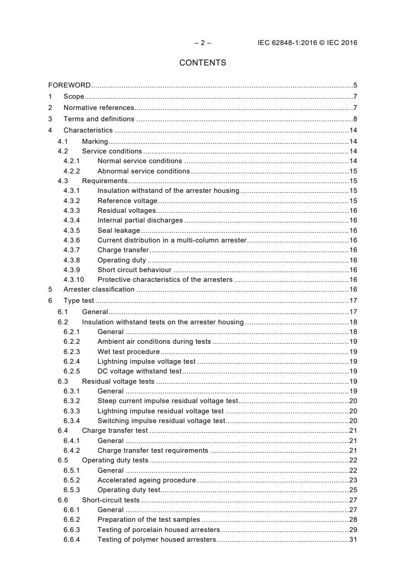
– 2 – IEC 62848-1:2016 © IEC 2016
CONTENTS
FOREWORD . 5
1 Scope . 7
2 Normative references. 7
3 Terms and definitions . 8
4 Characteristics . 14
4.1 Marking . 14
4.2 Service conditions . 14
4.2.1 Normal service conditions . 14
4.2.2 Abnormal service conditions . 15
4.3 Requirements . 15
4.3.1 Insulation withstand of the arrester housing . 15
4.3.2 Reference voltage . 15
4.3.3 Residual voltages . 16
4.3.4 Internal partial discharges . 16
4.3.5 Seal leakage . 16
4.3.6 Current distribution in a multi-column arrester . 16
4.3.7 Charge transfer . 16
4.3.8 Operating duty . 16
4.3.9 Short circuit behaviour . 16
4.3.10 Protective characteristics of the arresters . 16
5 Arrester classification . 16
6 Type test . 17
6.1 General . 17
6.2 Insulation withstand tests on the arrester housing . 18
6.2.1 General . 18
6.2.2 Ambient air conditions during tests . 19
6.2.3 Wet test procedure . 19
6.2.4 Lightning impulse voltage test . 19
6.2.5 DC voltage withstand test . 19
6.3 Residual voltage tests . 19
6.3.1 General . 19
6.3.2 Steep current impulse residual voltage test . 20
6.3.3 Lightning impulse residual voltage test . 20
6.3.4 Switching impulse residual voltage test . 20
6.4 Charge transfer test . 21
6.4.1 General . 21
6.4.2 Charge transfer test requirements . 21
6.5 Operating duty tests . 22
6.5.1 General . 22
6.5.2 Accelerated ageing procedure . 23
6.5.3 Operating duty test . 25
6.6 Short-circuit tests . 27
6.6.1 General . 27
6.6.2 Preparation of the test samples . 28
6.6.3 Testing of porcelain housed arresters . 29
6.6.4 Testing of polymer housed arresters . 31
6.6.5 Evaluation of test results . 33
6.7 Internal partial discharge tests . 34
6.8 Bending moment test . 34
6.8.1 General . 34
6.8.2 Test on porcelain and cast-resin housed arresters . 34
6.8.3 Test on polymer-housed arresters with and without enclosed gas
volume . 35
6.8.4 Definition of mechanical loads . 38
6.9 Seal leak rate test . 39
6.9.1 General . 39
6.9.2 Definition of seal leak rate . 39
6.9.3 Sample preparation . 40
6.9.4 Test procedure . 40
6.9.5 Test evaluation . 40
6.10 Environmental tests . 40
6.10.1 Weather ageing test for polymer-housed surge arresters . 40
6.10.2 Accelerated weathering test for polymer housed surge arresters and
cast resin housed surge arresters . 41
6.10.3 Temperature cycling test and salt mist test for porcelain and cast resin-
housed arresters . 42
6.11 Shock and vibration test . 43
7 Routine tests and acceptance tests . 43
7.1 Routine tests . 43
7.2 Acceptance tests . 43
Annex A (normative) Flowchart of testing procedure of bending moment . 44
Annex B (informative) Direct lightning current impulse withstand test . 45
Bibliography . 47
Figure 1 – Impulse current – Rectangular . 22
Figure 2 – Power losses of the metal-oxide resistor at elevated temperatures versus time . 24
Figure 3 – Short-circuit test setup for porcelain-housed arresters (all leads and venting
systems in the same plane) . 29
Figure 4 – Short circuit test setup for polymer housed arresters (all leads and venting
systems in the same plane) . 32
Figure 5 – Example of a test circuit for re-applying pre-failing immediately before
applying the short-circuit test current . 33
Figure 6 – Thermomechanical preconditioning . 36
Figure 7 – Example of the arrangement for the thermo-mechanical preconditioning and
directions of the cantilever load . 37
Figure 8 – Water immersion test . 38
Figure 9 – Definition of mechanical loads (base load = SSL) . 39
Figure 10 – Surge arrester unit. 39
Figure A.1 – Flowchart of testing procedure of bending moment . 44
Table 1 – Arrester classification . 17
Table 2 – Nominal discharge current . 17
Table 3 – Type tests . 18
Table 4 – Peak currents for switching impulse residual voltage test. 21
– 4 – IEC 62848-1:2016 © IEC 2016
Table 5 – Parameters for the charge transfer test . 21
Table 6 – Determination of elevated continuous operating voltage . 25
Table 7 – Test procedure of operating duty test . 25
Table 8 – Values for high current impulses . 26
Table 9 – Required currents for short-circuit tests of porcelain housed arresters . 30
Table 10 – Required currents for short-circuit tests . 32
Table B.1 – Parameters for the direct lightning impulse . 45
INTERNATIONAL ELECTROTECHNICAL COMMISSION
____________
RAILWAY APPLICATIONS – DC SURGE ARRESTERS
AND VOLTAGE LIMITING DEVICES –
Part 1: Metal-oxide surge arresters without gaps
FOREWORD
1) The International Electrotechnical Commission (IEC) is a worldwide organization for standardization comprising
all national electrotechnical committees (IEC National Committees). The object of IEC is to promote
international co-operation on all questions concerning standardization in the electrical and electronic fields. To
this end and in addition to other activities, IEC publishes International Standards, Technical Specifications,
Technical Reports, Publicly Available Specifications (PAS) and Guides (hereafter referred to as “IEC
Publication(s)”). Their preparation is entrusted to technical committees; any IEC National Committee interested
in the subject dealt with may participate in this preparatory work. International, governmental and non-
governmental organizations liaising with the IEC also participate in this preparation. IEC collaborates closely
with the International Organization for Standardization (ISO) in accordance with conditions determined by
agreement between the two organizations.
2) The formal decisions or agreements of IEC on technical matters express, as nearly as possible, an international
consensus of opinion on the relevant subjects since each technical committee has representation from all
interested IEC National Committees.
3) IEC Publications have the form of recommendations for international use and are accepted by IEC National
Committees in that sense. While all reasonable efforts are made to ensure that the technical content of IEC
Publications is accurate, IEC cannot be held responsible for the way in which they are used or for any
misinterpretation by any end user.
4) In order to promote international uniformity, IEC National Committees undertake to apply IEC Publications
transparently to the maximum extent possible in their national and regional publications. Any divergence
between any IEC Publication and the corresponding national or regional publication shall be clearly indicated in
the latter.
5) IEC itself does not provide any attestation of conformity. Independent certification bodies provide conformity
assessment services and, in some areas, access to IEC marks of conformity. IEC is not responsible for any
services carried out by independent certification bodies.
6) All users should ensure that they have the latest edition of this publication.
7) No liability shall attach to IEC or its directors, employees, servants or agents including individual experts and
members of its technical committees and IEC National Committees for any personal injury, property damage or
other damage of any nature whatsoever, whether direct or indirect, or for costs (including legal fees) and
expenses arising out of the publication, use of, or reliance upon, this IEC Publication or any other IEC
Publications.
8) Attention is drawn to the Normative references cited in this publication. Use of the referenced publications is
indispensable for the correct application of this publication.
9) Attention is drawn to the possibility that some of the elements of this IEC Publication may be the subject of
patent rights. IEC shall not be held responsible for identifying any or all such patent rights.
International Standard IEC 62848-1 has been prepared by IEC technical committee 9:
Electrical equipment and systems for railways.
This International Standard is based on EN 50526-1:2012, the main technical changes with
regard to EN 50526-1:2012 are as follows:
a) According to Resolution 52/33, taken by IEC technical committee 9, this international
standard should apply to both fixed installations and rolling stock, therefore the title is
replaced with “Railway applications – DC surge arresters and voltage limiting devices –
Part 1: Metal-oxide surge arresters without gaps”, and the scope of IEC 62848-1 is
modified so that the standard can be used in both cases.
b) As rolling stocks are supplied with many voltages as stated in IEC 60850, the surge
arrester will limit voltage surge on DC systems specified in IEC 60850 with nominal
voltage up to 3 kV.
c) The European standards, listed in the original EN 50526-1:2012, are replaced with
international standards, if they have corresponding international standards, as follows:
– 6 – IEC 62848-1:2016 © IEC 2016
1) EN 50124-1:2001→ IEC 62497-1:2010;
2) EN 50125-2:2002→ IEC 62498-2:2010;
3) EN 60060-1:2010→ IEC 60060-1:2010;
4) EN 60270:2001 →IEC 60270:2000;
5) EN 61109:2008→IEC 61109:2008;
6) EN ISO 4287:1998→ ISO 4287:1997;
7) EN ISO 4892-1:2000→ ISO 4892-1:1999;
8) EN ISO 4892-2:2006→ISO 4892-2:2006;
9) EN ISO 4892-3:2006→ISO 4892-3:2006.
d) As this international standard will be used for both rolling stock and fixed installation, the
following international standards relating to rolling stock are added:
1) IEC 62498 (all parts), Railway applications – Environmental conditions for equipment;
2) IEC 61373, Railway applications- Rolling stock equipment- Shock and vibration tests.
The text of this standard is based on the following documents:
FDIS Report on voting
9/2155/FDIS 9/2177/RVD
Full information on the voting for the approval of this standard can be found in the report on
voting indicated in the above table.
This publication has been drafted in accordance with the ISO/IEC Directives, Part 2.
A list of all parts in the IEC 62848 series, published under the general title Railway
applications – DC surge arresters and voltage limiting devices, can be found on the IEC
website.
The committee has decided that the contents of this publication will remain unchanged until
the stability date indicated on the IEC website under "http://webstore.iec.ch" in the data
related to the specific publication. At this date, the publication will be
• reconfirmed,
• withdrawn,
• replaced by a revised edition, or
• amended.
RAILWAY APPLICATIONS – DC SURGE ARRESTERS
AND VOLTAGE LIMITING DEVICES –
Part 1: Metal-oxide surge arresters without gaps
1 Scope
This part of IEC 62848 applies to non-linear metal-oxide surge arresters without gaps for both
on board and fixed installations, designed to limit voltage surges on DC systems specified in
IEC 60850 with nominal voltage up to 3 kV.
2 Normative references
The following documents, in whole or in part, are normatively referenced in this document and
are indispensable for its application. For dated references, only the edition cited applies. For
undated references, the latest edition of the referenced document (including any
amendments) applies.
IEC 60060-1:2010, High-voltage test techniques – Part 1: General definitions and test
requirements
IEC 60068-2-11:1981, Basic environmental testing procedures – Part 2-11: Tests – Test Ka:
Salt mist
IEC 60068-2-14, Environmental testing – Part 2-14: Tests – Test N: Change of temperature
IEC 60270:2000, High-voltage test techniques – Partial discharge measurements
IEC 61109:2008, Insulators for overhead lines – Composite suspension and tension insulators
for a.c. systems with a nominal voltage greater than 1 000 V – Definitions, test methods and
acceptance criteria
IEC 61373, Railway applications- Rolling stock equipment – Shock and vibration tests
IEC 62497-1:2010, Railway applications – Insulation coordination – Part 1: Basic
requirements – Clearances and creepage distances for all electrical and electronic equipment
IEC 62498 (all parts), Railway applications – Environmental conditions for equipment
IEC 62498-1:2010, Railway applications – Environmental conditions for equipment – Part 1:
Equipment on board rolling stock
IEC 62498-2:2010, Railway applications – Environmental conditions for equipment – Part 2:
Fixed electrical installations
ISO 4287:1997, Geometrical Product Specifications (GPS) – Surface texture: Profile method -
Terms, definitions and surface texture parameters
ISO 4892-1:1999, Plastics – Methods of exposure to laboratory light sources – Part 1:
General guidance
– 8 – IEC 62848-1:2016 © IEC 2016
ISO 4892-2:2013, Plastics – Methods of exposure to laboratory light sources – Part 2: Xenon-
arc lamps
ISO 4892-3:2016, Plastics – Methods of exposure to laboratory light sources – Part 3:
Fluorescent UV lamps
3 Terms and definitions
For the purposes of this document, the following terms and definitions apply.
3.1
nominal voltage
U
n
designated value for a system
[SOURCE: IEC 60850:2007, 3.3]
3.2
highest permanent voltage
U
max1
maximum value of the voltage likely to be present indefinitely
[SOURCE: IEC 60850:2007, 3.4]
3.3
highest non-permanent voltage
U
max2
maximum value of the voltage likely to be present for a limited period of time
[SOURCE: IEC 60850:2007, 3.5]
3.4
rated insulation voltage
U
Nm
DC withstand voltage value assigned by the manufacturer to the equipment or a part of it,
characterising the specified permanent (over 5 min) withstand capability of its insulation
[SOURCE: IEC 62497-1:2010, 3.4.4, modified – the rated insulation voltage is a DC withstand
voltage value for DC surge arrester and Note 1 to Note 4 have been deleted]
3.5
rated impulse withstand voltage
U
Ni
impulse voltage value assigned by the manufacturer to the equipment or a part of it,
characterising the specified withstand capability of its insulation against transient
overvoltages
[SOURCE: IEC 62497-1:2010, 3.4.7, modified – Note has been deleted.]
3.6
overvoltage
voltage having a peak value exceeding the corresponding peak value of the highest non-
permanent voltage U
max2
3.7
transient overvoltage
short duration overvoltage of a few milliseconds (up to 20 ms) or less associated with a
transient regime. Two particular transient overvoltages are defined: switching overvoltage and
lightning overvoltage
[SOURCE: IEC 62497-1:2010, 3.5.2, modified – Note has been deleted.]
3.8
switching overvoltage
transient overvoltage at any point of the system due to specific switching operation or fault
[SOURCE: IEC 62497-1:2010, 3.5.3]
3.9
lightning overvoltage
transient overvoltage at any point of the system due to a lightning discharge
[SOURCE: IEC 62497-1:2010, 3.5.4]
3.10
surge arrester
device intended to limit the transient overvoltages to a specified level
3.11
metal-oxide surge arrester
arrester having non-linear metal-oxide resistors connected in series and/or in parallel without
any integrated series or parallel spark gaps
3.12
continuous operating voltage of an arrester
U
c
designated permissible DC voltage value that may be applied continuously between the
arrester terminals
[SOURCE: IEC 60099-4:2009, 3.9, modified – the definition has been adapted for DC surge
arrester instead of AC surge arrester.]
3.13
rated voltage of an arrester
U
r
voltage by which the arrester is designated
Note 1 to entry: Because of the particular nature of the DC electrical installation dealt with, the rated voltage of a
DC arrester coincides with the continuous operating voltage.
3.14
elevated continuous operating voltage
U *
c
test voltage U * that, when applied to new metal-oxide resistor, gives the same power losses
c
as the voltage U when applied to aged metal-oxide resistors
c
3.15
lightning impulse protection level
U
pl
maximum residual voltage for the nominal discharge current
– 10 – IEC 62848-1:2016 © IEC 2016
3.16
switching impulse protection level
U
ps
maximum residual voltage at the specified switching impulse current
3.17
charge transfer capability
Q
t
maximum charge per impulse that can be transferred during the charge transfer test and
during the operating duty test
3.18
discharge current of an arrester
impulse current which flows through the arrester
3.19
nominal discharge current of an arrester
I
n
peak value of lightning current impulse which is used to classify an arrester
[SOURCE: IEC 60099-4:2009, 3.30]
3.20
high current impulse of an arrester
peak value of discharge current having a 4/10 µs impulse shape which is used to test the
stability of the arrester on direct lightning strokes
[SOURCE: IEC 60099-4:2009, 3.31]
3.21
steep current impulse
current impulse with a virtual front time of 1 µs with limits in the adjustment of equipment such
that the measured values are from 0,9 µs to 1,1 µs and the virtual time to half-value on the tail
is not longer than 20 µs
[SOURCE: IEC 60099-4:2009, 3.16, modified – Note has been deleted.]
3.22
lightning current impulse
8/20 current impulse with limits on the adjustment of equipment such that the measured
values are from 7 µs to 9 µs for the virtual front time and from 18 µs to 22 µs for the time to
half-value on the tail
[SOURCE: IEC 60099-4:2009, 3.17]
3.23
direct lightning current impulse
impulse defined by the charge Q and the peak value of the current impulse I
imp
3.24
switching current impulse of an arrester
I
sw
peak value of discharge current having a virtual front time greater than 30 µs but less than
100 µs and a virtual time to half value on the tail of roughly twice the virtual front time
[SOURCE: IEC 60099-4:2009, 3.32]
3.25
reference current of an arrester
I
ref
DC current defined by the manufacturer used to determine the reference voltage of the
arrester
Note 1 to entry: The reference current will be typically in the range of 0,01 mA to 0,5 mA per square centimetre of
disc area for single column arrester.
3.26
reference voltage of an arrester
U
ref
DC voltage which is applied to the arrester to obtain the reference current
Note 1 to entry: For asymmetrical U/I characteristics, the lower value of the two voltages shall be used to
determine the reference voltage.
[SOURCE: IEC 60099-9:2014, 3.49, modified – Note 1 has been adapted and Note 2 deleted.]
3.27
residual voltage of an arrester
U
res
peak value of voltage that appears between the terminals of an arrester during the passage of
discharge current
[SOURCE: IEC 60099-4:2009, 3.36]
3.28
rated short circuit current of an arrester
I
s
maximum current that may flow in case of an arrester failure for a specified time
3.29
shed
insulating part projecting from the housing, intended to increase the creepage distance
[SOURCE: IEC 60099-4:2009, 3.46.2]
3.30
porcelain-housed arrester
arrester using porcelain as housing material, with fittings and sealing systems
[SOURCE: IEC 60099-4:2009, 3.59]
3.31
polymer-housed arrester
arrester using polymeric and/or composite materials for housing
[SOURCE: IEC 60099-4:2009, 3.60, modified – this definition has been adapted and Note has
been deleted.]
3.32
cast-resin housed arrester
arrester using a housing made from organic hard material that fractures similarly to a
porcelain housing under mechanical overstress
– 12 – IEC 62848-1:2016 © IEC 2016
3.33
bending moment
horizontal force acting on the arrester housing multiplied by the vertical distance between the
mounting base (lower level of the flange) of the arrester housing and the point of application
of the force
[SOURCE: IEC 60099-4:2009, 3.61]
3.34
torsional loading
horizontal force at the top of a vertical mounted arrester housing which is not applied to the
longitudinal axis of the arrester
[SOURCE: IEC 60099-4:2009, 3.63, modified – “each” deleted]
3.35
breaking load
force perpendicular to the longitudinal axis of a porcelain-housed arrester leading to
mechanical failure of the arrester housing
[SOURCE: IEC 60099-4:2009, 3.64]
3.36
mean breaking load
MBL
average breaking load for porcelain arresters determined from tests
Note 1 to entry: Adapted from IEC 60099-4:2009, Clause A.2.
3.37
specified long-term load
SLL
force perpendicular to the longitudinal axis of an arrester, allowed to be continuously applied
during service without causing any mechanical damage to the arrester
[SOURCE: IEC 60099-4:2009, 3.66]
3.38
specified short-term load
SSL
greatest force perpendicular to the longitudinal axis of an arrester, allowed to be applied
during service for short periods and for relatively rare events (for example, short-circuit
current loads, extreme wind gusts) without causing any mechanical damage to the arrester
[SOURCE: IEC 60099-4: 2009, 3.67]
3.39
non-linear metal-oxide resistor
part of the surge arrester which, by its non-linear voltage versus current characteristic, acts
as a low resistance to overvoltages, thus limiting the voltage across the arrester terminals,
and as a high resistance at normal operating voltage
[SOURCE: IEC 60099-4:2009, 3.2]
3.40
pressure-relief device of an arrester
means for relieving internal pressure in an arrester and preventing violent shattering of the
housing following prolonged passage of fault current or internal flashover of the arrester
[SOURCE: IEC 60099-4:2009, 3.7]
3.41
internal parts
metal-oxide resistor element with supporting structure
[SOURCE: IEC 60099-4:2009, 3.69]
3.42
seal
gas/water tightness
ability of an arrester to avoid ingress of matter affecting the electrical and/or mechanical
behaviour into the arrester
[SOURCE: IEC 60099-4:2009, 3.70]
3.43
disruptive discharge
phenomena associated with the failure of insulation under electric stress, which include a
collapse of voltage and the passage of current
Note 1 to entry: The term applies to electrical breakdowns in solid, liquid and gaseous dielectric, and
combinations of these.
[SOURCE: IEC 60099-4:2009, 3.11, modified]
3.44
puncture
breakdown
disruptive discharge through a solid
[SOURCE: IEC 60099-4:2009, 3.12]
3.45
flashover
disruptive discharge over a solid surface
[SOURCE: IEC 60099-4:2009, 3.13]
3.46
impulse
unidirectional wave of voltage or current which without appreciable oscillations rises rapidly to
a maximum value and falls, usually less rapidly, to zero with small, if any, excursions of
opposite polarity
Note 1 to entry: The parameters which define a voltage or current impulse are polarity, peak value, front time and
time to half value on the tail.
[SOURCE: IEC 60099-4:2009, 3.14]
3.47
type test
design test
conformity test made on one or more items representative of the production
[SOURCE: IEC 60050-151:2001, 151-16-16]
– 14 – IEC 62848-1:2016 © IEC 2016
3.48
routine test
conformity test made on each individual item during or after manufacture
[SOURCE: IEC 60050-151:2001, 151-16-17]
3.49
acceptance test
contractual test to prove to the customer that the item meets certain conditions of its
specification
[SOURCE: IEC 60050-151: 2001, 151-16-23]
3.50
prospective short circuit current
current which would flow in a circuit if it were short-circuited by a link of negligible impedance
4 Characteristics
4.1 Marking
Surge arresters shall be identified by the following minimum information which shall appear on
the rating plate (nameplate):
• rated voltage U = U ;
r c
• nominal discharge current I in kA;
n
• rated short circuit current I in kA;
s
• manufacturer's name or trademark, type and identification;
• year of manufacture;
• serial number;
• arrester class.
NOTE The rated voltage of a DC metal-oxide arresters coincides with continuous operating voltage as per the
operating duty test.
Conditions in AC systems:
According to IEC 60099-4:2009, 3.8, the rated voltage of a surge arrester is defined as the maximum permissible
RMS value of power-frequency voltage between its terminals at which it is designed to operate correctly under
long-term overvoltage conditions as established in the operating duty test. The rated voltage is the 10 s power-
frequency voltage used in the operating duty test after high-current or long-duration impulses. U is applied for
c
30 min immediately after the application of rated voltage in the operating duty test where thermal stability has to be
demonstrated. Typically the ratio between rated voltage and U is about 1,25 for surge arresters in AC systems
c
corresponding to a specific long-term overvoltage, which may occur during fault conditions in the AC system.
Conditions in DC systems:
According to IEC 60850 the supply voltages of traction systems are defined. The highest non-permanent voltage
U is defined for durations from 1 s to 5 min. By selection of the surge arrester by U > U , the operating
max2 c max2
duty test as specified in 6.5 covers all effects of long-term overvoltages longer than 1 s with significant margin. No
higher long-term overvoltages, which could be assigned to a “rated voltage” occur in DC systems.
4.2 Service conditions
4.2.1 Normal service conditions
Surge arresters which conform to this international standard shall be suitable for operation
under the following normal service conditions:
a) ambient temperature within the range of –40 °C to +40 °C;
b) solar radiation (see 4.8 of IEC 62498-2:2010);
c) altitude not exceeding 1 400 m (from IEC 62498 series);
d) pollution not exceeding PD 1 for indoor installations and PD 4 for outdoor installations as
given in IEC 62497-1;
e) installation in the vicinity of a rail track on foundations designed so as to damp the main
effects of the passage of the trains. Nevertheless a limited vibration or limited shocks may
affect the equipment, which shall be capable of operating satisfactorily when subjected to
the following conventional accelerations separately applied:
– vertical acceleration (g ): 5 m/s ;
v
– horizontal acceleration (g ): 5 m/s ;
h
f) surge arresters for onboard rolling stock shall be able to withstand vibrations and shocks
that occur in service as defined in IEC 61373;
g) surge arrester shall comply with the wind conditions as defined in 4.4.1 of
IEC 62498-2:2010 or air movement condition as defined in 4.5 of IEC 62498-1:2010.
4.2.2 Abnormal service conditions
The following are typical abnormal service conditions which may require special consideration
in the manufacture or application of surge arresters and should be called to the attention of
the manufacturer:
a) temperature in excess of +40 °C or below –40 °C;
b) application at altitudes higher than 1 400 m;
c) fumes or vapours which may cause deterioration of insulating surface or mounting
hardware;
d) excessive contamination by smoke, dirt, salt spray or other conducting materials;
e) excessive exposure to moisture, humidity, dropping water or steam;
f) live washing of arrester;
g) explosive mixtures of dust, gases or fumes;
h) abnormal mechanical conditions (earthquakes, vibrations, high ice loads, high cantilever
stresses);
i) unusual transportation or storage;
j) heat sources near the arrester;
k) non-vertical erection and suspended erection;
l) torsional loading of the arrester;
m) tensile loading of the arrester;
n) use of the arrester as a mechanical support.
4.3 Requirements
4.3.1 Insulation withstand of the arrester housing
The insulation of the arrester housing shall be coordinated with the arrester protective
characteristics. Tests shall be performed according to 6.2.
4.3.2 Reference voltage
Measurement of reference voltage is necessary for the selection of a correct test sample in
the operating duty test, see 6.5. The reference voltage of a DC surge arrester is measured at
a specific reference current, The reference current is typically in the range of 0,05 mA to
1,0 mA per square centimetre of the disc area for single column arresters. The minimum
reference voltage of the arrester at the reference current used for routine tests shall be
specified and published in the manufacturer’s data.
– 16 – IEC 62848-1:2016 © IEC 2016
4.3.3 Residual voltages
The maximum residual voltages for a given design and for all specified currents and wave
shapes shall be obtained from the type test data and from the maximum residual voltage at a
lightning impulse current used for the routine test as specified and published by the
manufacturer. The maximum residual voltage of a given arrester design for any current and
wave shape shall be calculated from the residual voltage of samples tested during type test
multiplied by a specific scale factor. This scale factor is equal to the ratio of the declared
maximum residual voltage, as checked during the routine test, to the measured residual
voltage of the samples at the same current and wave shape.
4.3.4 Internal partial discharges
The internal partial discharges of the arrester energized at 1,05 times its continuous operating
voltage shall not exceed 10 pC.
4.3.5 Seal leakage
For arresters having an enclosed gas volume and a separate sealing system, seal leak rates
shall be specified as defined in 6.9.
4.3.6 Current distribution in a multi-column arrester
The manufacturer shall specify the unbalance of the current distribution in a multicolumn
arrester.
4.3.7 Charge transfer
Arresters shall be able to withstand the charge transfer test as specified in 6.4.
4.3.8 Operating duty
Arresters shall be able to withstand the combination of stresses arising in service as
demonstrated by the operating duty tests, see 6.5.
4.3.9 Short circuit behaviour
Arresters shall be able to withstand a short circuit test as specified in 6.6. The arrester shall
not fail in a manner that causes violent shattering of the housing and that self-extinguishing of
open flames (if any) occurs
...
Questions, Comments and Discussion
Ask us and Technical Secretary will try to provide an answer. You can facilitate discussion about the standard in here.
Loading comments...