

IEC 60127-7:2026
(Main)Miniature fuses - Part 7: Miniature fuse-links for special applications
General Information
- Abstract
IEC 60127-7:2026 covers requirements for miniature fuse-links for special applications. This part of IEC 60127 is applicable to fuse-links with a rated voltage not exceeding 1 000 V, a rated current not exceeding 125 A and a rated breaking capacity not exceeding 50 kA. It does not apply to fuses completely covered by the subsequent parts of IEC 60269-1. It does not apply to miniature fuse-links for appliances intended to be used under special conditions, such as in corrosive or explosive atmospheres.
- Status
- Published
- Publication Date
- 26-May-2026
- Technical Committee
- SC 32C - Miniature fuses
- Drafting Committee
- MT 10 - TC 32/SC 32C/MT 10
- Current Stage
- PPUB - Publication issued
- Start Date
- 27-May-2026
- Completion Date
- 08-May-2026
Buy Documents
IEC 60127-7:2026 - Miniature fuses - Part 7: Miniature fuse-links for special applications
REDLINE IEC 60127-7:2026 RLV - Miniature fuses - Part 7: Miniature fuse-links for special applications
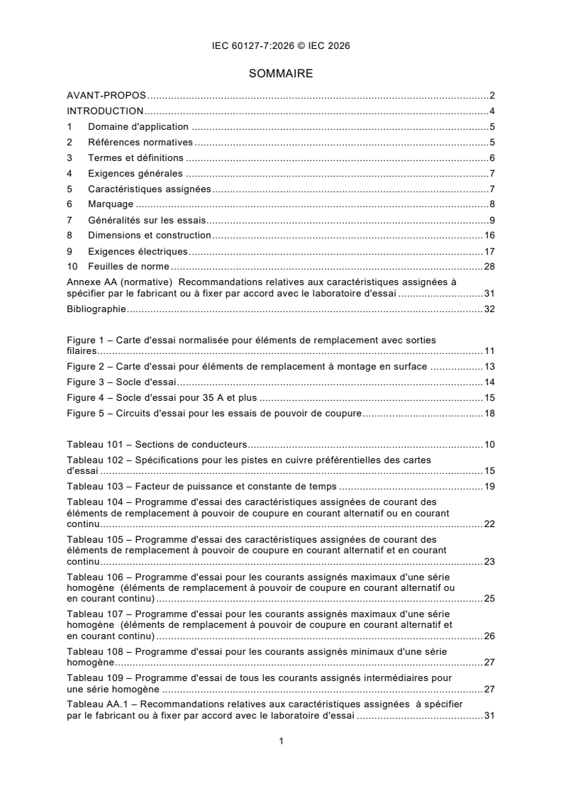
IEC 60127-7:2026 - Coupe-circuit miniatures - Partie 7: Eléments de remplacement miniatures pour applications spéciales
Overview
IEC 60127-7:2026 - Miniature fuses – Part 7: Miniature fuse-links for special applications specifies the requirements, testing methods, and terminology for miniature fuse-links designed for unique or specialized electrical and electronic applications. Developed by the International Electrotechnical Commission (IEC), this standard covers miniature fuse-links with a rated voltage up to 1,000 V, a rated current up to 125 A, and a rated breaking capacity up to 50 kA. It augments the general requirements of IEC 60127-1 and is intended for fuse-links not fully addressed in other IEC 60127 or IEC 60269 standards.
This part is key to ensuring safety, reliability, and performance in environments where typical miniature fuses may not meet operational or regulatory needs, but does not cover fuse-links used in corrosive or explosive environments.
Key Topics
Scope and Terminology
- Defines the characteristics and specific requirements for special miniature fuse-links.
- Applies to fuse-links not covered by other parts of the IEC 60127 series or by IEC 60269-1.
- Clarifies that these fuses are generally not intended for end-user replacement.
Electrical and Mechanical Ratings
- Rated voltage: ≤ 1,000 V
- Rated current: ≤ 125 A
- Rated breaking capacity: ≤ 50 kA
Construction and Marking
- Requirements for enclosed fuse-elements and materials resistant to heat and fire.
- Mandates clear marking of type designation and breaking capacity on the part or packaging.
- Prohibits standardized color codes to avoid confusion with other fuse types, except for unique manufacturer markings.
Testing Methods
- Uniform test schedules for individual ratings and series.
- Use of specific test boards, fuse-holders, and materials for mounting (including provisions for surface-mount and through-hole types).
- Robust checks for endurance, voltage drop, mechanical strength, and breaking capacity, with specific sample sizes and criteria.
Environmental and Safety Performance
- Includes guidance on material selection, such as glow-wire tests for plastics.
- Specifies mechanical robustness and corrosion resistance for terminals.
- Details test conditions for elevated temperature performance.
Applications
Miniature fuse-links for special applications are critical in:
- Custom Electrical Equipment: Ideal for equipment requiring non-standard overcurrent protection not covered by mainstream fuse-types.
- Industrial Electronic Systems: Suitable for power supplies, control devices, and assemblies with specific performance criteria.
- Surface Mount and Through-Hole Designs: Supports both modern PCB assembly methods in compact or densely populated assemblies.
- Proprietary or OEM Devices: Common in applications where fuse replacement is intended only during servicing, not by the end-user.
By conforming to IEC 60127-7:2026, manufacturers ensure consistent product reliability across global markets, facilitate conformity assessments, and support safety objectives in specialized electronic and electrical equipment.
Related Standards
- IEC 60127-1: Definitions and general requirements for miniature fuses (essential companion standard).
- IEC 60127-2: Cartridge fuse-links.
- IEC 60127-3: Sub-miniature fuse-links.
- IEC 60127-4: Universal modular fuse-links (UMF) for through-hole and surface-mount types.
- IEC 60127-5: Guidelines for quality assessment of miniature fuse-links.
- IEC 60127-6: Fuse-holders for miniature fuse-links.
- IEC 60695 Series: Fire hazard testing for electrical products.
- IEC 61249-2-7: Materials for printed boards, relevant for test board construction.
Keywords: IEC 60127-7, miniature fuses, fuse-links for special applications, fuse standards, electronic component safety, miniature fuse testing, overcurrent protection, PCB fuses, IEC standards, electrical safety compliance.
For further information and the latest updates, refer to the official IEC website and the specific standard documentation.
Relations
- Effective Date
- 10-Nov-2023
Buy Documents
IEC 60127-7:2026 - Miniature fuses - Part 7: Miniature fuse-links for special applications
REDLINE IEC 60127-7:2026 RLV - Miniature fuses - Part 7: Miniature fuse-links for special applications
IEC 60127-7:2026 - Coupe-circuit miniatures - Partie 7: Eléments de remplacement miniatures pour applications spéciales
Get Certified
Connect with accredited certification bodies for this standard

IMQ S.p.A. (Certification)
Italian electrical product certification.

SLG Prüf- und Zertifizierungs GmbH
German testing and certification body.

UL Solutions
Global safety science company with testing, inspection and certification.
Sponsored listings
Frequently Asked Questions
IEC 60127-7:2026 is a standard published by the International Electrotechnical Commission (IEC). Its full title is "Miniature fuses - Part 7: Miniature fuse-links for special applications". This standard covers: IEC 60127-7:2026 covers requirements for miniature fuse-links for special applications. This part of IEC 60127 is applicable to fuse-links with a rated voltage not exceeding 1 000 V, a rated current not exceeding 125 A and a rated breaking capacity not exceeding 50 kA. It does not apply to fuses completely covered by the subsequent parts of IEC 60269-1. It does not apply to miniature fuse-links for appliances intended to be used under special conditions, such as in corrosive or explosive atmospheres.
IEC 60127-7:2026 covers requirements for miniature fuse-links for special applications. This part of IEC 60127 is applicable to fuse-links with a rated voltage not exceeding 1 000 V, a rated current not exceeding 125 A and a rated breaking capacity not exceeding 50 kA. It does not apply to fuses completely covered by the subsequent parts of IEC 60269-1. It does not apply to miniature fuse-links for appliances intended to be used under special conditions, such as in corrosive or explosive atmospheres.
IEC 60127-7:2026 is classified under the following ICS (International Classification for Standards) categories: 29.120.50 - Fuses and other overcurrent protection devices. The ICS classification helps identify the subject area and facilitates finding related standards.
IEC 60127-7:2026 has the following relationships with other standards: It is inter standard links to IEC 60127-7:2015. Understanding these relationships helps ensure you are using the most current and applicable version of the standard.
IEC 60127-7:2026 is available in PDF format for immediate download after purchase. The document can be added to your cart and obtained through the secure checkout process. Digital delivery ensures instant access to the complete standard document.
Standards Content (Sample)
IEC 60127-7 ®
Edition 3.0 2026-05
INTERNATIONAL
STANDARD
Miniature fuses -
Part 7: Miniature fuse-links for special application
ICS 29.120.50 ISBN 978-2-8327-1221-4
All rights reserved. Unless otherwise specified, no part of this publication may be reproduced or utilized in any form or
by any means, electronic or mechanical, including photocopying and microfilm, without permission in writing from either
IEC or IEC's member National Committee in the country of the requester. If you have any questions about IEC copyright
or have an enquiry about obtaining additional rights to this publication, please contact the address below or your local
IEC member National Committee for further information.
IEC Secretariat Tel.: +41 22 919 02 11
3, rue de Varembé info@iec.ch
CH-1211 Geneva 20 www.iec.ch
Switzerland
About the IEC
The International Electrotechnical Commission (IEC) is the leading global organization that prepares and publishes
International Standards for all electrical, electronic and related technologies.
About IEC publications
The technical content of IEC publications is kept under constant review by the IEC. Please make sure that you have the
latest edition, a corrigendum or an amendment might have been published.
IEC publications search - IEC Products & Services Portal - products.iec.ch
webstore.iec.ch/advsearchform Discover our powerful search engine and read freely all the
The advanced search enables to find IEC publications by a publications previews, graphical symbols and the glossary.
variety of criteria (reference number, text, technical With a subscription you will always have access to up to date
committee, …). It also gives information on projects, content tailored to your needs.
replaced and withdrawn publications.
Electropedia - www.electropedia.org
The world's leading online dictionary on electrotechnology,
IEC Just Published - webstore.iec.ch/justpublished
Stay up to date on all new IEC publications. Just Published containing more than 22 500 terminological entries in English
details all new publications released. Available online and and French, with equivalent terms in 25 additional languages.
once a month by email. Also known as the International Electrotechnical Vocabulary
(IEV) online.
IEC Customer Service Centre - webstore.iec.ch/csc
If you wish to give us your feedback on this publication or
need further assistance, please contact the Customer
Service Centre: sales@iec.ch.
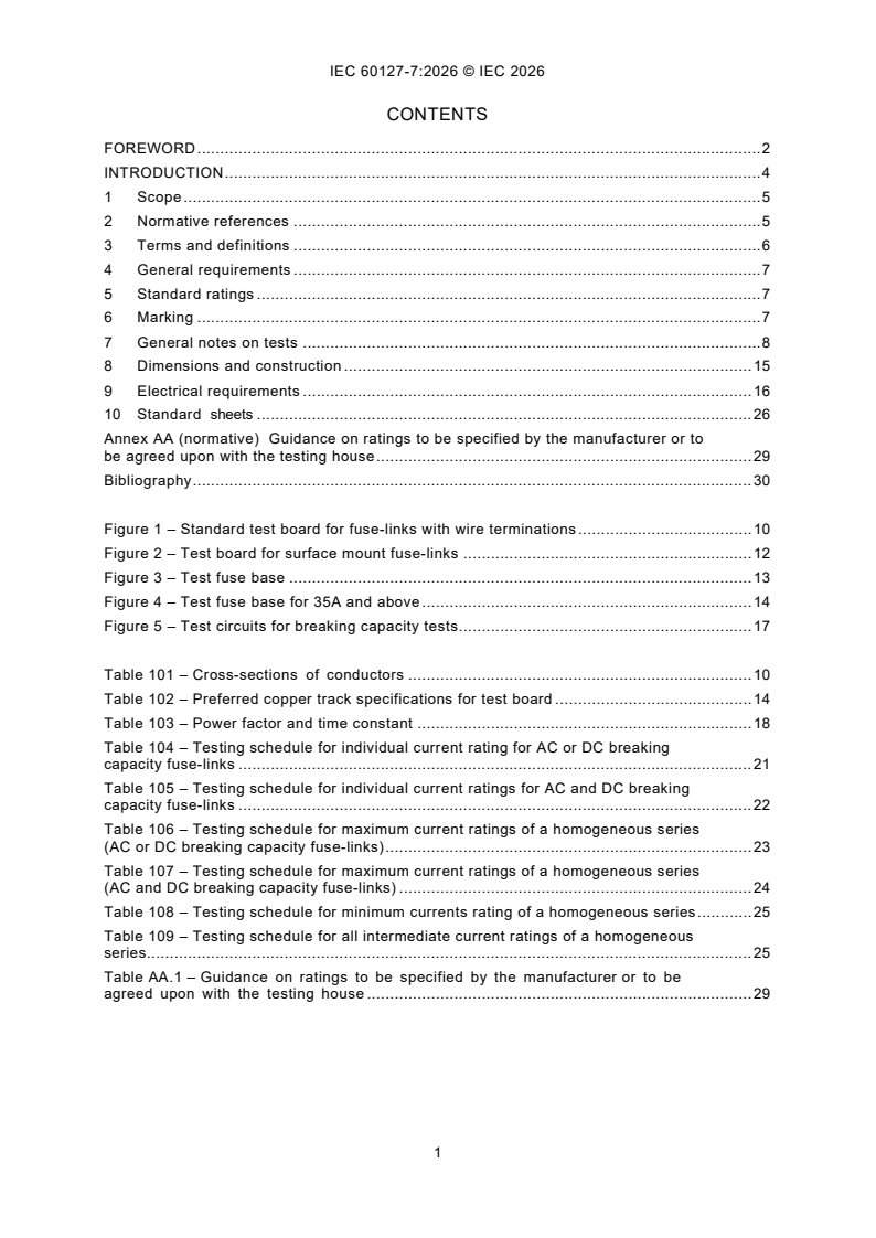
CONTENTS
FOREWORD . 2
INTRODUCTION . 4
1 Scope . 5
2 Normative references . 5
3 Terms and definitions . 6
4 General requirements . 7
5 Standard ratings . 7
6 Marking . 7
7 General notes on tests . 8
8 Dimensions and construction . 15
9 Electrical requirements . 16
10 Standard sheets . 26
Annex AA (normative) Guidance on ratings to be specified by the manufacturer or to
be agreed upon with the testing house . 29
Bibliography . 30
Figure 1 – Standard test board for fuse-links with wire terminations . 10
Figure 2 – Test board for surface mount fuse-links . 12
Figure 3 – Test fuse base . 13
Figure 4 – Test fuse base for 35A and above . 14
Figure 5 – Test circuits for breaking capacity tests . 17
Table 101 – Cross-sections of conductors . 10
Table 102 – Preferred copper track specifications for test board . 14
Table 103 – Power factor and time constant . 18
Table 104 – Testing schedule for individual current rating for AC or DC breaking
capacity fuse-links . 21
Table 105 – Testing schedule for individual current ratings for AC and DC breaking
capacity fuse-links . 22
Table 106 – Testing schedule for maximum current ratings of a homogeneous series
(AC or DC breaking capacity fuse-links) . 23
Table 107 – Testing schedule for maximum current ratings of a homogeneous series
(AC and DC breaking capacity fuse-links) . 24
Table 108 – Testing schedule for minimum currents rating of a homogeneous series . 25
Table 109 – Testing schedule for all intermediate current ratings of a homogeneous
series. 25
Table AA.1 – Guidance on ratings to be specified by the manufacturer or to be
agreed upon with the testing house . 29
INTERNATIONAL ELECTROTECHNICAL COMMISSION
____________
Miniature fuses -
Part 7: Miniature fuse-links for special application
FOREWORD
1) The International Electrotechnical Commission (IEC) is a worldwide organization for standardization comprising
all national electrotechnical committees (IEC National Committees). The object of IEC is to promote international
co-operation on all questions concerning standardization in the electrical and electronic fields. To this end and
in addition to other activities, IEC publishes International Standards, Technical Specifications, Technical Reports,
Publicly Available Specifications (PAS) and Guides (hereafter referred to as “IEC Publication(s)”). Their
preparation is entrusted to technical committees; any IEC National Committee interested in the subject dealt with
may participate in this preparatory work. International, governmental and non-governmental organizations liaising
with the IEC also participate in this preparation. IEC collaborates closely with the International Organization for
Standardization (ISO) in accordance with conditions determined by agreement between the two organizations.
2) The formal decisions or agreements of IEC on technical matters express, as nearly as possible, an international
consensus of opinion on the relevant subjects since each technical committee has representation from all
interested IEC National Committees.
3) IEC Publications have the form of recommendations for international use and are accepted by IEC National
Committees in that sense. While all reasonable efforts are made to ensure that the technical content of IEC
Publications is accurate, IEC cannot be held responsible for the way in which they are used or for any
misinterpretation by any end user.
4) In order to promote international uniformity, IEC National Committees undertake to apply IEC Publications
transparently to the maximum extent possible in their national and regional publications. Any divergence between
any IEC Publication and the corresponding national or regional publication shall be clearly indicated in the latter.
5) IEC itself does not provide any attestation of conformity. Independent certification bodies provide conformity
assessment services and, in some areas, access to IEC marks of conformity. IEC is not responsible for any
services carried out by independent certification bodies.
6) All users should ensure that they have the latest edition of this publication.
7) No liability shall attach to IEC or its directors, employees, servants or agents including individual experts and
members of its technical committees and IEC National Committees for any personal injury, property damage or
other damage of any nature whatsoever, whether direct or indirect, or for costs (including legal fees) and
expenses arising out of the publication, use of, or reliance upon, this IEC Publication or any other IEC
Publications.
8) Attention is drawn to the Normative references cited in this publication. Use of the referenced publications is
indispensable for the correct application of this publication.
9) IEC draws attention to the possibility that the implementation of this document may involve the use of (a)
patent(s). IEC takes no position concerning the evidence, validity or applicability of any claimed patent rights in
respect thereof. As of the date of publication of this document, IEC had not received notice of (a) patent(s), which
may be required to implement this document. However, implementers are cautioned that this may not represent
the latest information, which may be obtained from the patent database available at https://patents.iec.ch. IEC
shall not be held responsible for identifying any or all such patent rights.
IEC 60127-7 has been prepared by subcommittee 32C: Miniature fuses, of IEC technical
committee 32: Fuses. It is an International Standard.
This third edition cancels and replaces the second edition published in 2015. This edition
constitutes a technical revision.
This edition includes the following significant technical changes with respect to the previous
edition:
a) alignment with IEC 60127-1:2023 (third edition);
b) change of the rated current of miniature fuse-links for special application to 125A and
provision of relevant requirements;
c) addition of a test board for surface mount fuse-links (Figure 2);
d) addition of test schedules for homogenous series.
This part of IEC 60127 is to be read in conjunction with Part 1. It supplements or modifies the
corresponding clauses of Part 1. Where the text indicates an "addition" to or a "replacement" of
the relevant provision of Part 1, these changes are made to the relevant text of Part 1. When a
particular subclause of Part 1 is not mentioned in this part, that subclause applies as far as is
reasonable.
Additional specific provisions to those in Part 1, given as individual clauses or subclauses, are
numbered starting from 101.
NOTE The following numbering system is used:
– subclauses, tables and figures that are numbered starting from 101 are additional to those in Part 1;
– unless notes are in a new subclause or involve notes in Part 1, they are numbered starting from 101, including
those in a replaced clause or subclause;
– additional annexes are lettered AA, BB, etc.
The text of this International Standard is based on the following documents:
Draft Report on voting
32C/679/FDIS 32C/681/RVD
Full information on the voting for its approval can be found in the report on voting indicated in
the above table.
The language used for the development of this International Standard is English.
A list of all parts in the IEC 60127 series, published under the general title Miniature fuses, can
be found on the IEC website.
This document was drafted in accordance with ISO/IEC Directives, Part 2, and developed in
accordance with ISO/IEC Directives, Part 1 and ISO/IEC Directives, IEC Supplement, available
at www.iec.ch/members_experts/refdocs. The main document types developed by IEC are
described in greater detail at www.iec.ch/publications.
The committee has decided that the contents of this document will remain unchanged until the
stability date indicated on the IEC website under webstore.iec.ch in the data related to the
specific document. At this date, the document will be
– reconfirmed,
– withdrawn, or
– revised.
INTRODUCTION
According to the wish expressed by the users of miniature fuses, all standards,
recommendations and other documents relating to miniature fuses have the same publication
number in order to facilitate reference to fuses in other specifications, for example, equipment
specifications.
Furthermore, a single publication number and subdivision into parts would facilitate the
establishment of new standards, because clauses and subclauses containing general
requirements need not be repeated.
The new IEC 60127 series is thus subdivided as follows:
IEC 60127, Miniature fuses (general title)
IEC 60127-1, Miniature fuses - Part 1: Definitions for miniature fuses and general requirements
for miniature fuse-links
IEC 60127-2, Miniature fuses - Part 2: Cartridge fuse-links
IEC 60127-3, Miniature fuses - Part 3: Sub-miniature fuse-links
IEC 60127-4, Miniature fuses - Part 4: Universal modular fuse-links (UMF) - Through-hole and
surface mount types
IEC 60127-5, Miniature fuses - Part 5: Guidelines for quality assessment of miniature fuse- links
IEC 60127-6, Miniature fuses - Part 6: Fuse-holders for miniature fuse-links
IEC 60127-7, Miniature fuses - Part 7: Miniature fuse-links for special applications
IEC 60127-8, Miniature fuses - Part 8: Fuse resistors with particular overcurrent protection
IEC 60127-9, Miniature fuses - Part 9: Miniature fuse-links for special applications with partial-
range breaking capacity
IEC 60127-10, (withdrawn)
This part of IEC 60127 covers additional requirements, test equipment and standard sheets.
The SI system of units is used throughout this document.
1 Scope
This part of IEC 60127 covers requirements for miniature fuse-links for special applications.
This part of IEC 60127 is applicable to fuse-links with a rated voltage not exceeding 1 000 V, a
rated current not exceeding 125 A and a rated breaking capacity not exceeding 50 kA.
NOTE Nominal currents above 20 A are intended for protection of low power electric devices at low voltage and not
for energy distribution.
It does not apply to fuses completely covered by the subsequent parts of IEC 60269-1.
It does not apply to miniature fuse-links for appliances intended to be used under special
conditions, such as in corrosive or explosive atmospheres.
This part of IEC 60127 applies in addition to the requirements of IEC 60127-1:2023.
Miniature fuse-links for special applications are not intended to be replaced by the end-user of
an electrical / electronic appliance.
The object of this part of IEC 60127 is to establish uniform test methods for miniature fuse-links
for special applications, so as to allow verification of the values (for example melting time and
breaking capacity values) specified by the manufacturer.
2 Normative references
The following documents are referred to in the text in such a way that some or all of their content
constitutes requirements of this document. For dated references, only the edition cited applies.
For undated references, the latest edition of the referenced document (including any
amendments) applies.
IEC 60068-2-21:2021, Environmental testing - Part 2-21: Tests - Test U: Robustness of
terminations and integral mounting devices
IEC 60127-1:2023, Miniature fuses - Part 1: Definitions for miniature fuses and general
requirements for miniature fuse-links
IEC 60127-4:2026, Miniature fuses - Part 4: Universal modular fuse-links (UMF) - Through-hole
and surface mount types
IEC 60127-6:2023, Miniature fuses - Part 6: Fuse-holders for miniature fuse-links
IEC 60664-1:2020, Insulation coordination for equipment within low-voltage systems - Part 1:
Principles, requirements and tests
IEC 60695-2-12:2021, Fire hazard testing - Part 2-12: Glowing/hot-wire based test methods -
Glow-wire flammability index (GWFI) test method for materials
IEC 60695-2-13:2021, Fire hazard testing - Part 2-13: Glowing/hot-wire based test methods -
Glow-wire ignition temperature (GWIT) test method for materials
IEC 60695-4:2021, Fire hazard testing - Part 4: Terminology concerning fire tests for
electrotechnical products
IEC 61249-2-7:2002, Materials for printed boards and other interconnecting structures -
Part 2-7: Reinforced base materials clad and unclad - Epoxide woven E-glass laminated sheet
of defined flammability (vertical burning test), copper-clad
ISO 3:1973, Preferred numbers - Series of preferred numbers
3 Terms and definitions
For the purposes of this document, the terms and definitions given in Clause 3 of
IEC 60127-1:2023, except 3.5, and the following apply.
ISO and IEC maintain terminology databases for use in standardization at the following
addresses:
– IEC Electropedia: available at https://www.electropedia.org/
– ISO Online browsing platform: available at https://www.iso.org/obp
3.1
miniature fuse-link for special applications
enclosed fuse-link which is not covered in IEC 60127-2, IEC 60127-3 or IEC 60127-4 and of
rated breaking capacity not exceeding 50 kA, with a width and height not exceeding 12 mm and
a length not exceeding 50 mm
Note 1 to entry: Special precautions may be necessary to ensure that the fuse-links will be replaced by a fuse-link
with the same technical parameters.
Note 2 to entry: For fuse-links having a metallic cap at each end, any member of terminals or terminations other
than the metallic cap such as wire terminations, pins and bolt-in contacts may not be included in the total length of
50 mm and the width and height of 12 mm.
3.2
t to t
1 8
limit values for time/current characteristic
3.3
I
test current for testing at elevated temperature of 70 °C
Note 1 to entry: Preferred values are 0,8 I or 1,0 I or 1,1 I .
N N N
3.4
I (A)
test
test current for endurance testing according to method A
Note 1 to entry: Preferred values are 1,0 I or 1,05 I or 1,2 I .
N N N
3.5
I (B)
test
test current for endurance testing according to method B
Note 1 to entry: Preferred values are 0,8 I or 1,0 I .
N N
3.6
I (A)
OVL
test current for measuring the maximum sustained power dissipation according to method
A
Note 1 to entry: Preferred values are 1,0 I or 1,25 I or 1,35 I or 1,5 I . 1,0 I is allowable only for nominal
N N N N N
currents above 20 A.
3.7
I (B)
OVL
test current for measuring the maximum sustained power dissipation according to method B
Note 1 to entry: Preferred values are 1,0 I or 1,25 I .
N N
4 General requirements
Clause 4 of IEC 60127-1:2023 applies.
5 Standard ratings
Replace Clause 5 of IEC 60127-1:2023 as follows:
The following ratings shall be agreed upon between the testing house and the manufacturer:
– rated voltage;
– rated current (see standard sheet 1 for preferred ratings);
– rated breaking capacity (AC and/or DC);
– time/current characteristic (at least at 2,0 I or 2,1 I and 10 I ).
N N N
The following may be agreed upon on an optional basis:
– test at elevated temperature;
and 4 I ).
– time/current characteristic (additionally at 2,75 I
N N
Any additional specified values are given in standard sheet 1. Guidance on ratings to be
specified by the manufacturer or to be agreed upon with the testing house is given in Annex AA.
6 Marking
Clause 6 of IEC 60127-1:2023 applies except as follows.
6.1
Replace a) of Subclause 6.1 as follows:
a) Not applicable.
NOTE A symbol denoting the time/current characteristic cannot be stated, because this part of IEC 60127 does not
specify any values for this parameter.
Addition:
e) Type designation.
f) Rated breaking capacity in amperes (A) or in kilo amperes (kA).
6.2
Deletion of NOTE.
6.3
Addition after first paragraph:
Furthermore, the rated breaking capacity in amperes (A) or in kilo amperes (kA) shall be marked
on the package label.
6.4
Addition of heading title and replacement of text:
6.4 Colour coding for miniature fuse-links for special applications
Marking of fuse-links by means of colour bands according to IEC 60127-1:2023, Annex A, is not
permitted. It is, however, possible to use colour markings that clearly differ from this colour
band system. In this case, the manufacturer shall provide the relevant information, for example
colour key.
Additional subclause:
6.101 Where marking is impracticable due to space limitations, the relevant information should
appear on the smallest package and in the manufacturer’s technical literature.
7 General notes on tests
Clause 7 of IEC 60127-1:2023 applies except as follows.
7.3 Type tests
7.3.1
Replacement:
For testing the individual current ratings of fuses with AC or DC breaking capacity, the number
of fuse-links required is 51, of which 12 are kept as spares. For fuse-links with wire terminations
six extra samples (E1 to E6) have to be taken by random and not sorted according to voltage
drop. If necessary, these samples can be used as additional spares after performing the tests
according to 8.3.
The testing schedule is shown in Table 104.
For testing the individual current ratings of fuses with AC and DC breaking capacity, the number
of fuse-links required is 63, of which 9 are kept as spares. For fuse-links with wire terminations
six extra samples (E1 to E6) have to be taken by random and not sorted according to voltage
drop. If necessary, these samples can be used as additional spares after performing the tests
according to 8.3. The testing schedule is shown in Table 105.
For testing the maximum current rating of a homogenous series with AC or DC breaking capacity
the number of fuse-links required is 51, of which 22 are kept as spares. For fuse-links with wire
terminations six extra samples (E1 to E6) have to be taken by random and not sorted according
to voltage drop. If necessary, these samples can be used as additional spares after performing
the tests according to 8.3.
The testing schedule is shown in Table 106.
For testing the maximum current rating of a homogenous series with AC and DC breaking
capacity the number of fuse-links required is 66, of which 32 are kept as spares. For fuse-links
with wire terminations six extra samples (E1 to E6) have to be taken by random and not sorted
according to voltage drop. If necessary, these samples can be used as additional spares after
performing the tests according to 8.3.
The testing schedule is shown in Table 107.
For testing the minimum current rating of a homogenous series with AC and/or DC breaking
capacity the number of fuse-links required is 38, of which 16 are kept as spares.
The testing schedule is shown in Table 108.
For testing all of the intermediate current rating of a homogenous series with AC and/or DC
breaking capacity the number of fuse-links required is 38, of which 16 are kept as spares.
The testing schedule is shown in Table 109.
7.4 Fuse-bases for tests
Addition after first paragraph:
For fuse-links designed for use in a special type of fuse-holder, testing shall be performed in
that fuse-holder. Fuse-holder information shall be supplied to users in manufacturer’s literature.
For tests that require a printed circuit board for mounting and connection of the fuse-links, a
test board according to Figure 1 or Figure 2 shall be used.
The test board according to Figure 1 shall be used for fuse links with wire terminations intended
for insertion in suitably designed holes or sockets.
The test board according to Figure 2 shall be used for surface mount fuse-links. The test board
shall be made of epoxide woven glass fabric copper-clad laminated sheet, as defined in
IEC 61249-2-7. The manufacturer must declare the PCB parameters and provide assembled
PCBs for the tests.
This test board shall then be mounted on the test fuse-base (Figure 3 or Figure 4).
When two or more fuse-links are tested in series, the fuse-bases shall be located so that there
will be a spacing of not less than 50 mm between any two fuse-links under testing. The
conductor connecting the fuse-bases together and connecting the fuse-bases to the ammeter
and the source of supply shall be insulated copper wire. The length of each conductor shall be
500 mm. The cross-sectional area of the wire shall be according to Table 101.
Table 101 – Cross-sections of conductors
Rated current Copper conductor cross sectional area
A
mm
Up to and including 5 1
More than 5, and up to and including 10 1,5
More than 10, and up to and including 16 2,5
More than 16, and up to and including 25 4
More than 25, and up to and including 35 6
More than 35, and up to and including 60 35
More than 60, and up to and including 125 50
Dimensions in millimetres
Key
O copper layer, refer to Table 102
U connection for voltage drop measurement
D can be any shape. Size shall be as specified by the manufacturer
e 2,5 mm
n 1, 2, 3 … (to be adapted depending on the length of the fuse-link)
TW Track width. 10 mm if TW less than or equal to 10 mm, Equal to TW if greater than 10 mm
Radius only used for rounded through-hole shaped terminations. Size as specified by Manufacturer
Figure 1 – Standard test board for fuse-links with wire terminations
This test board shall be mounted on the fuse-base according to Figure 3a).
Figure 1 displays an example for through-hole (round terminations). Other termination types
and shapes are acceptable.
Dimensions in millimetres
a) test board A
b) test board B
Key
O copper layer thickness, refer to Table 102
U connection for voltage drop measurement. The connection tracks are covered by the solder resist and should
be placed as to minimize the voltage drop during operation while ensuring a minimum separation of 1 mm for
galvanic insulation (L)
TW Track width, refer to Table 102. For small devices, it may be necessary to use reduced track widths,
representi
...
IEC 60127-7 ®
Edition 3.0 2026-05
INTERNATIONAL
STANDARD
REDLINE VERSION
Miniature fuses -
Part 7: Miniature fuse-links for special application
ICS 29.120.50 ISBN 978-2-8327-1275-7
All rights reserved. Unless otherwise specified, no part of this publication may be reproduced or utilized in any form or
by any means, electronic or mechanical, including photocopying and microfilm, without permission in writing from either
IEC or IEC's member National Committee in the country of the requester. If you have any questions about IEC copyright
or have an enquiry about obtaining additional rights to this publication, please contact the address below or your local
IEC member National Committee for further information.
IEC Secretariat Tel.: +41 22 919 02 11
3, rue de Varembé info@iec.ch
CH-1211 Geneva 20 www.iec.ch
Switzerland
About the IEC
The International Electrotechnical Commission (IEC) is the leading global organization that prepares and publishes
International Standards for all electrical, electronic and related technologies.
About IEC publications
The technical content of IEC publications is kept under constant review by the IEC. Please make sure that you have the
latest edition, a corrigendum or an amendment might have been published.
IEC publications search - IEC Products & Services Portal - products.iec.ch
webstore.iec.ch/advsearchform Discover our powerful search engine and read freely all the
The advanced search enables to find IEC publications by a publications previews, graphical symbols and the glossary.
variety of criteria (reference number, text, technical With a subscription you will always have access to up to date
committee, …). It also gives information on projects, content tailored to your needs.
replaced and withdrawn publications.
Electropedia - www.electropedia.org
The world's leading online dictionary on electrotechnology,
IEC Just Published - webstore.iec.ch/justpublished
Stay up to date on all new IEC publications. Just Published containing more than 22 500 terminological entries in English
details all new publications released. Available online and and French, with equivalent terms in 25 additional languages.
once a month by email. Also known as the International Electrotechnical Vocabulary
(IEV) online.
IEC Customer Service Centre - webstore.iec.ch/csc
If you wish to give us your feedback on this publication or
need further assistance, please contact the Customer
Service Centre: sales@iec.ch.
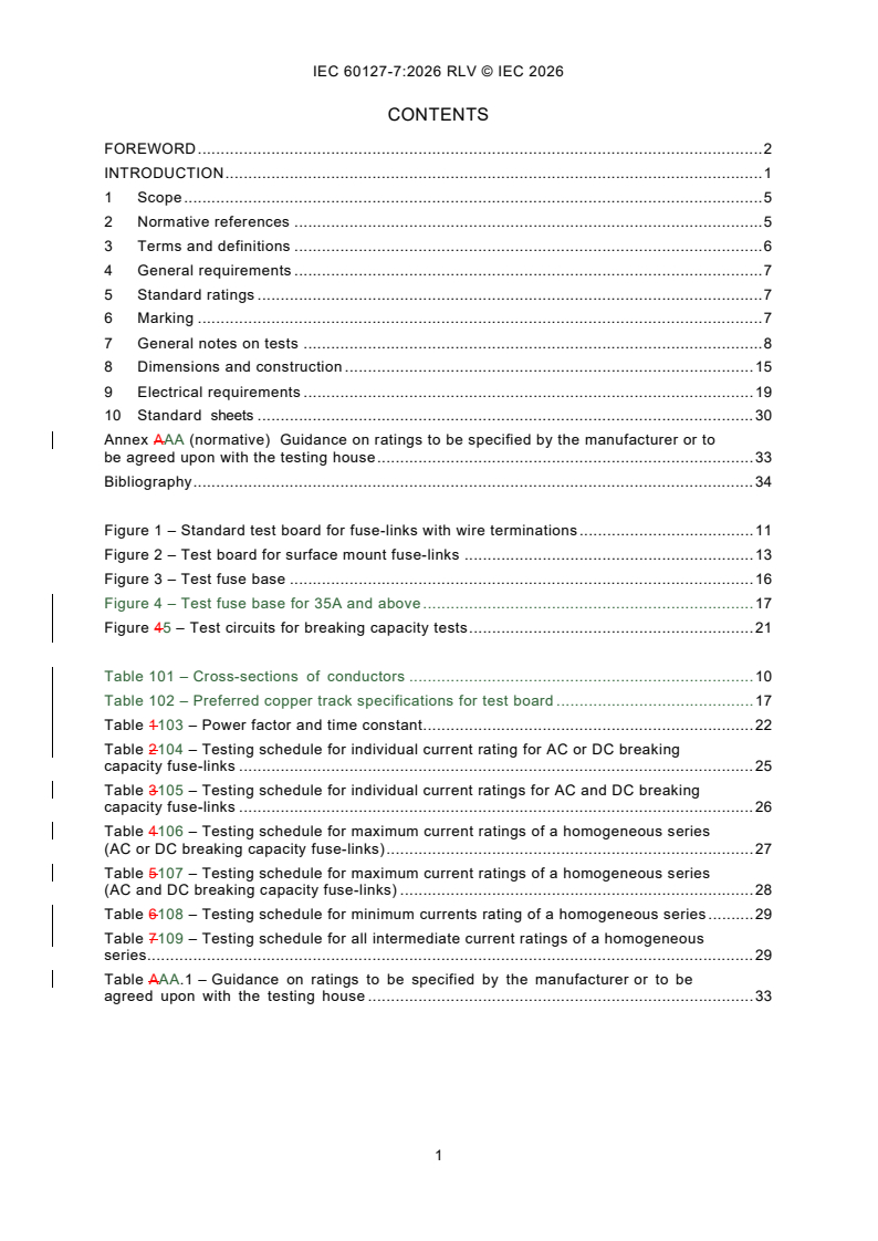
CONTENTS
FOREWORD . 2
INTRODUCTION . 1
1 Scope . 5
2 Normative references . 5
3 Terms and definitions . 6
4 General requirements . 7
5 Standard ratings . 7
6 Marking . 7
7 General notes on tests . 8
8 Dimensions and construction . 15
9 Electrical requirements . 19
10 Standard sheets . 30
Annex AAA (normative) Guidance on ratings to be specified by the manufacturer or to
be agreed upon with the testing house . 33
Bibliography . 34
Figure 1 – Standard test board for fuse-links with wire terminations . 11
Figure 2 – Test board for surface mount fuse-links . 13
Figure 3 – Test fuse base . 16
Figure 4 – Test fuse base for 35A and above . 17
Figure 45 – Test circuits for breaking capacity tests . 21
Table 101 – Cross-sections of conductors . 10
Table 102 – Preferred copper track specifications for test board . 17
Table 1103 – Power factor and time constant. 22
Table 2104 – Testing schedule for individual current rating for AC or DC breaking
capacity fuse-links . 25
Table 3105 – Testing schedule for individual current ratings for AC and DC breaking
capacity fuse-links . 26
Table 4106 – Testing schedule for maximum current ratings of a homogeneous series
(AC or DC breaking capacity fuse-links) . 27
Table 5107 – Testing schedule for maximum current ratings of a homogeneous series
(AC and DC breaking capacity fuse-links) . 28
Table 6108 – Testing schedule for minimum currents rating of a homogeneous series . 29
Table 7109 – Testing schedule for all intermediate current ratings of a homogeneous
series. 29
Table AAA.1 – Guidance on ratings to be specified by the manufacturer or to be
agreed upon with the testing house . 33
INTERNATIONAL ELECTROTECHNICAL COMMISSION
____________
Miniature fuses -
Part 7: Miniature fuse-links for special application
FOREWORD
1) The International Electrotechnical Commission (IEC) is a worldwide organization for standardization comprising
all national electrotechnical committees (IEC National Committees). The object of IEC is to promote international
co-operation on all questions concerning standardization in the electrical and electronic fields. To this end and
in addition to other activities, IEC publishes International Standards, Technical Specifications, Technical Reports,
Publicly Available Specifications (PAS) and Guides (hereafter referred to as “IEC Publication(s)”). Their
preparation is entrusted to technical committees; any IEC National Committee interested in the subject dealt with
may participate in this preparatory work. International, governmental and non-governmental organizations liaising
with the IEC also participate in this preparation. IEC collaborates closely with the International Organization for
Standardization (ISO) in accordance with conditions determined by agreement between the two organizations.
2) The formal decisions or agreements of IEC on technical matters express, as nearly as possible, an international
consensus of opinion on the relevant subjects since each technical committee has representation from all
interested IEC National Committees.
3) IEC Publications have the form of recommendations for international use and are accepted by IEC National
Committees in that sense. While all reasonable efforts are made to ensure that the technical content of IEC
Publications is accurate, IEC cannot be held responsible for the way in which they are used or for any
misinterpretation by any end user.
4) In order to promote international uniformity, IEC National Committees undertake to apply IEC Publications
transparently to the maximum extent possible in their national and regional publications. Any divergence between
any IEC Publication and the corresponding national or regional publication shall be clearly indicated in the latter.
5) IEC itself does not provide any attestation of conformity. Independent certification bodies provide conformity
assessment services and, in some areas, access to IEC marks of conformity. IEC is not responsible for any
services carried out by independent certification bodies.
6) All users should ensure that they have the latest edition of this publication.
7) No liability shall attach to IEC or its directors, employees, servants or agents including individual experts and
members of its technical committees and IEC National Committees for any personal injury, property damage or
other damage of any nature whatsoever, whether direct or indirect, or for costs (including legal fees) and
expenses arising out of the publication, use of, or reliance upon, this IEC Publication or any other IEC
Publications.
8) Attention is drawn to the Normative references cited in this publication. Use of the referenced publications is
indispensable for the correct application of this publication.
9) IEC draws attention to the possibility that the implementation of this document may involve the use of (a)
patent(s). IEC takes no position concerning the evidence, validity or applicability of any claimed patent rights in
respect thereof. As of the date of publication of this document, IEC had not received notice of (a) patent(s), which
may be required to implement this document. However, implementers are cautioned that this may not represent
the latest information, which may be obtained from the patent database available at https://patents.iec.ch. IEC
shall not be held responsible for identifying any or all such patent rights.
This redline version of the official IEC Standard allows the user to identify the changes made
to the previous edition IEC 60127-7:2015. A vertical bar appears in the margin wherever a
change has been made. Additions are in green text, deletions are in strikethrough red text.
IEC 60127-7 has been prepared by subcommittee 32C: Miniature fuses, of IEC technical
committee 32: Fuses. It is an International Standard.
This third edition cancels and replaces the second edition published in 2015. This edition
constitutes a technical revision.
This edition includes the following significant technical changes with respect to the previous
edition:
a) alignment with IEC 60127-1:2023 (third edition);
b) change of the rated current of miniature fuse-links for special application to 125A and
provision of relevant requirements;
c) addition of a test board for surface mount fuse-links (Figure 2);
d) addition of test schedules for homogenous series.
This part of IEC 60127 is to be read in conjunction with Part 1. It supplements or modifies the
corresponding clauses of Part 1. Where the text indicates an "addition" to or a "replacement" of
the relevant provision of Part 1, these changes are made to the relevant text of Part 1. When a
particular subclause of Part 1 is not mentioned in this part, that subclause applies as far as is
reasonable.
Additional specific provisions to those in Part 1, given as individual clauses or subclauses, are
numbered starting from 101.
NOTE The following numbering system is used:
– subclauses, tables and figures that are numbered starting from 101 are additional to those in Part 1;
– unless notes are in a new subclause or involve notes in Part 1, they are numbered starting from 101, including
those in a replaced clause or subclause;
– additional annexes are lettered AA, BB, etc.
The text of this International Standard is based on the following documents:
Draft Report on voting
32C/679/FDIS 32C/681/RVD
Full information on the voting for its approval can be found in the report on voting indicated in
the above table.
The language used for the development of this International Standard is English.
A list of all parts in the IEC 60127 series, published under the general title Miniature fuses, can
be found on the IEC website.
This document was drafted in accordance with ISO/IEC Directives, Part 2, and developed in
accordance with ISO/IEC Directives, Part 1 and ISO/IEC Directives, IEC Supplement, available
at www.iec.ch/members_experts/refdocs. The main document types developed by IEC are
described in greater detail at www.iec.ch/publications.
The committee has decided that the contents of this document will remain unchanged until the
stability date indicated on the IEC website under webstore.iec.ch in the data related to the
specific document. At this date, the document will be
– reconfirmed,
– withdrawn, or
– revised.
INTRODUCTION
According to the wish expressed by the users of miniature fuses, all standards,
recommendations and other documents relating to miniature fuses should have the same
publication number in order to facilitate reference to fuses in other specifications, for example,
equipment specifications.
Furthermore, a single publication number and subdivision into parts would facilitate the
establishment of new standards, because clauses and subclauses containing general
requirements need not be repeated.
The new IEC 60127 series, under the general heading Miniature fuses, is thus subdivided as
follows:
IEC 60127, Miniature fuses (general title)
IEC 60127-1, Miniature fuses - Part 1: Definitions for miniature fuses and general requirements
for miniature fuse-links
IEC 60127-2, Miniature fuses - Part 2: Cartridge fuse-links
IEC 60127-3, Miniature fuses - Part 3: Sub-miniature fuse-links
IEC 60127-4, Miniature fuses - Part 4: Universal modular fuse-links (UMF) - Through-hole and
surface mount types
IEC 60127-5, Miniature fuses - Part 5: Guidelines for quality assessment of miniature fuse- links
IEC 60127-6, Miniature fuses - Part 6: Fuse-holders for miniature fuse-links
IEC 60127-7, Miniature fuses - Part 7: Miniature fuse-links for special applications
IEC 60127-8, (Free for further documents) Miniature fuses - Part 8: Fuse resistors with
particular overcurrent protection
IEC 60127-9, (Free for further documents) Miniature fuses - Part 9: Miniature fuse-links for
special applications with partial-range breaking capacity
IEC 60127-10, Miniature fuses – Part 10: User guide for miniature fuses (withdrawn)
This part of IEC 60127 covers additional requirements, test equipment and standard sheets.
The SI system of units is used throughout this document.
1 Scope
This part of IEC 60127 covers requirements for miniature fuse-links for special applications.
This part of IEC 60127 is applicable to fuse-links with a rated voltage not exceeding 1 000 V, a
rated current not exceeding 20 125 A and a rated breaking capacity not exceeding 50 kA.
NOTE Nominal currents above 20 A are intended for protection of low power electric devices at low voltage and not
for energy distribution.
It does not apply to fuses completely covered by the subsequent parts of IEC 60269-1.
It does not apply to miniature fuse-links for appliances intended to be used under special
conditions, such as in corrosive or explosive atmospheres.
This part of IEC 60127 applies in addition to the requirements of IEC 60127-1:2023.
Miniature fuse-links for special applications are not intended to be replaced by the end-user of
an electrical / electronic appliance.
The object of this part of IEC 60127 is to establish uniform test methods for miniature fuse-links
for special applications, so as to allow verification of the values (for example melting time and
breaking capacity values) specified by the manufacturer.
2 Normative references
The following documents are referred to in the text in such a way that some or all of their content
constitutes requirements of this document. For dated references, only the edition cited applies.
For undated references, the latest edition of the referenced document (including any
amendments) applies.
IEC 60068-2-21:20062021, Environmental testing - Part 2-21: Tests - Test U: Robustness of
terminations and integral mounting devices
IEC 60127-1:20062023, Miniature fuses - Part 1: Definitions for miniature fuses and general
requirements for miniature fuse-links
IEC 60127-1:2006/AMD1:2011
IEC 60127-1:2006/AMD2:2015
IEC 60127-4:20052026, Miniature fuses - Part 4: Universal modular fuse-links (UMF) - Through-
hole and surface mount types
IEC 60127-4:2005/AMD1:2008
IEC 60127-4:2005/AMD2:2012
IEC 60127-6:20142023, Miniature fuses - Part 6: Fuse-holders for miniature fuse-links
IEC 60664-1:20072020, Insulation coordination for equipment within low-voltage systems - Part
1: Principles, requirements and tests
IEC 60695-2-12:20102021, Fire hazard testing - Part 2-12: Glowing/hot-wire based test
methods - Glow-wire flammability index (GWFI) test method for materials
IEC 60695-2-12:2010/AMD1:2014
IEC 60695-2-13:20102021, Fire hazard testing - Part 2-13: Glowing/hot-wire based test
methods - Glow-wire ignition temperature (GWIT) test method for materials
IEC 60695-2-13:2010/AMD1:2014
IEC 60695-4:20122021, Fire hazard testing - Part 4: Terminology concerning fire tests for
electrotechnical products
IEC 61249-2-7:2002, Materials for printed boards and other interconnecting structures -
Part 2-7: Reinforced base materials clad and unclad - Epoxide woven E-glass laminated sheet
of defined flammability (vertical burning test), copper-clad
ISO 3:1973, Preferred numbers - Series of preferred numbers
3 Terms and definitions
For the purposes of this document, the terms and definitions given in Clause 3 of
IEC 60127-1:20062023, except 3.5, and the following apply.
ISO and IEC maintain terminology databases for use in standardization at the following
addresses:
– IEC Electropedia: available at https://www.electropedia.org/
– ISO Online browsing platform: available at https://www.iso.org/obp
3.1
miniature fuse-link for special applications
enclosed fuse-link which is not covered in IEC 60127-2, IEC 60127-3 or IEC 60127-4 and of
rated breaking capacity not exceeding 50 kA, with a width and height not exceeding 12 mm and
a length not exceeding 50 mm
Note 1 to entry: Special precautions may be necessary to ensure that the fuse-links will be replaced by a fuse-link
with the same technical parameters.
Note 2 to entry: For fuse-links having a metallic cap at each end, any member of terminals or terminations other
than the metallic cap such as wire terminations, pins and bolt-in contacts may not be included in the total length of
50 mm and the width and height of 12 mm.
3.2
t to t
1 8
limit values for time/current characteristic
3.3
I
test current for testing at elevated temperature of 70 °C
Note 1 to entry: Preferred values are 0,8 I or 1,0 I or 1,1 I .
N N N
3.4
I (A)
test
test current for endurance testing according to method A
Note 1 to entry: Preferred values are 1,0 I or 1,05 I or 1,2 I .
N N N
3.5
I (B)
test
test current for endurance testing according to method B
Note 1 to entry: Preferred values are 0,8 I or 1,0 I .
N N
3.6
I (A)
OVL
test current for measuring the maximum sustained power dissipation according to method
A
Note 1 to entry: Preferred values are 1,0 I or 1,25 I or 1,35 I or 1,5 I . 1,0 I is allowable only for nominal
N N N N N
currents above 20 A.
3.7
I (B)
OVL
test current for measuring the maximum sustained power dissipation according to method B
Note 1 to entry: Preferred values are 1,0 I or 1,25 I .
N N
4 General requirements
Clause 4 of IEC 60127-1:20062023 applies.
5 Standard ratings
Replace Clause 5 of IEC 60127-1:20062023 as follows:
The following ratings shall be agreed upon between the testing house and the manufacturer:
– rated voltage;
– rated current (see standard sheet 1 for preferred ratings);
– rated breaking capacity (AC and/or DC);
– time/current characteristic (at least at 2,0 I or 2,1 I and 10 I ).
N N N
The following may be agreed upon on an optional basis:
– test at elevated temperature;
and 4 I ).
– time/current characteristic (additionally at 2,75 I
N N
Any additional specified values are given in standard sheet 1. Guidance on ratings to be
specified by the manufacturer or to be agreed upon with the testing house is given in Annex AA.
6 Marking
Clause 6 of IEC 60127-1:20062023 applies except as follows.
6.1
Replacement:
d) Not applicable.
Replace a) of Subclause 6.1 as follows:
a) Not applicable.
NOTE A symbol denoting the time/current characteristic cannot be stated, because this part of IEC 60127 does not
specify any values for this parameter.
Addition:
e) Type designation.
f) Rated breaking capacity in amperes (A) or in kilo amperes (kA).
6.2
Deletion of NOTE 2.
6.3
Addition after first paragraph:
Furthermore, the rated breaking capacity in amperes (A) or in kilo amperes (kA) shall be marked
on the package label.
6.4
Addition of heading title and replacement of text:
6.4 Colour coding for miniature fuse-links for special applications
Marking of fuse-links by means of colour bands according to IEC 60127-1:20062023, Annex A,
is not permitted. It is, however, possible to use colour markings that clearly differ from this
colour band system. In this case, the manufacturer shall provide the relevant information, for
example colour key.
Additional subclause:
6.101 Where marking is impracticable due to space limitations, the relevant information should
appear on the smallest package and in the manufacturer’s technical literature.
7 General notes on tests
Clause 7 of IEC 60127-1:20062023 applies except as follows.
7.23 Type tests
7.23.1
Replacement:
For testing the individual current ratings of fuses with AC or DC breaking capacity, the number
of fuse-links required is 51, of which 12 are kept as spares. For fuse-links with wire terminations
six extra samples (E1 to E6) have to be taken by random and not sorted according to voltage
drop. If necessary, these samples can be used as additional spares after performing the tests
according to 8.3.
The testing schedule is shown in Table 2 Table 104.
For testing the individual current ratings of fuses with AC and DC breaking capacity, the number
of fuse-links required is 63, of which 9 are kept as spares. For fuse-links with wire terminations
six extra samples (E1 to E6) have to be taken by random and not sorted according to voltage
drop. If necessary, these samples can be used as additional spares after performing the tests
according to 8.3. The testing schedule is shown in Table 3 Table 105.
For testing the maximum ampere current rating of a homogenous series with AC or DC breaking
capacity the number of fuse-links required is 51, of which 22 are kept as spares. For fuse-links
with wire terminations six extra samples (E1 to E6) have to be taken by random and not sorted
according to voltage drop. If necessary, these samples can be used as additional spares after
performing the tests according to 8.3.
The testing schedule is shown in Table 4 Table 106.
For testing the maximum ampere current rating of a homogenous series with AC and DC
breaking capacity the number of fuse-links required is 66, of which 32 are kept as spares. For
fuse-links with wire terminations six extra samples (E1 to E6) have to be taken by random and
not sorted according to voltage drop. If necessary, these samples can be used as additional
spares after performing the tests according to 8.3.
The testing schedule is shown in Table 5 Table 107.
For testing the minimum ampere current rating of a homogenous series with AC and/or DC
breaking capacity the number of fuse-links required is 38, of which 16 are kept as spares.
The testing schedule is shown in Table 6 Table 108.
For testing all of the intermediate ampere current rating of a homogenous series with AC and/or
DC breaking capacity the number of fuse-links required is 38, of which 16 are kept as spares.
The testing schedule is shown in Table 7 Table 109.
7.34 Fuse-bases for tests
Addition after first paragraph:
For fuse-links designed for use in a special type of fuse-holder, testing shall be performed in
that fuse-holder. Fuse-holder information shall be supplied to users in manufacturer’s literature.
For tests that require a printed circuit board for mounting and connection of the fuse-links, a
test board according to Figure 1 or Figure 2 shall be used.
The test board according to Figure 1 shall be used for fuse links with wire terminations intended
for insertion in suitably designed holes or sockets.
The test board according to Figure 2 shall be used for surface mount fuse-links. The test board
shall be made of epoxide woven glass fabric copper-clad laminated sheet, as defined in
IEC 61249-2-7. The manufacturer must declare the PCB parameters and provide assembled
PCBs for the tests.
This test board shall then be mounted on the test fuse-base (Figure 3 or Figure 4).
When two or more fuse-links are tested in series, the fuse-bases shall be located so that there
will be a spacing of not less than 50 mm between any two fuse-links under testing. The
conductor connecting the fuse-bases together and connecting the fuse-bases to the ammeter
and the source of supply shall be insulated copper wire. The length of each conductor shall be
500 mm and the cross-sectional area of the wire shall be approximately 1 mm for fuse-links
with rated currents up to and including 6,3 A, and 6 mm for rated currents exceeding 6,3 A.
The cross-sectional area of the wire shall be according to Table 101.
Table 101 – Cross-sections of conductors
Rated current Copper conductor cross sectional area
A
mm
Up to and including 5 1
More than 5, and up to and including 10 1,5
More than 10, and up to and including 16 2,5
More than 16, and up to and including 25 4
More than 25, and up to and including 35 6
More than 35, and up to and including 60 35
More than 60, and up to and including 125 50
Dimensions in millimetres
∅4,2
O
U
U
n × e
Figure 1A
∅ D
n × e
Radius =
IEC
Key
O copper layer; thickness 0,035 mm or 0,070 mm
U connection for voltage drop measurement
D diameter of 1 mm for rated currents up to and including 6,3 A;
diameter of 1,5 mm for rated currents exceeding 6,3 A.
e 2,5 mm
n 1, 2, 3, 4
n 1, 2, 3 … (to be adapted depending on the length of the fuse-link)
n × e
16,5 3
Key
O copper layer, refer to Table 102
U connection for voltage drop measurement
D can be any shape. Size shall be as specified by the manufacturer
e 2,5 mm
n 1, 2, 3 … (to be adapted depending on the length of the fuse-link)
TW Track width. 10 mm if TW less than or equal to 10 mm, Equal to TW if greater than 10 mm
Radius only used for rounded through-hole shaped terminations. Size as specified by Manufacturer
Figure 1 – Standard test board for fuse-links with wire terminations
This test board shall be mounted on the fuse-base according to Figure 3a).
Figure 1 displays an example for through-hole (round terminations). Other termination types
and shapes are acceptable.
Dimensions in millimetres
P 2T
U O Track width U (20)
Solder resist
IEC
Key
O copper layer, thickness 0,035 mm or 0,070 mm
U connection for voltage drop measurement
W tracking width equals n x e referring to Figure 1. For small devices, it may be necessary to use reduced track
widths, representing normal use of these devices. This should be recorded in the test report and in the
manufacturer's literature.
P terminal spacing
R refer to standard sheet 1, page 1
T refer to standard sheet 1, page 1
NOTE 1 Solder resist to be applied in hatched areas.
10,0
∅4,2
R1,5
W 0,5
16,5
a) test board A
b) test board B
Key
O copper layer thickness, refer to Table 102
U connection for voltage drop measurement. The connection tracks are covered by the solder resist and should
be placed as to minimize the voltage drop during operation while ensuring a minimum separation of 1 mm for
galvanic insulation (L)
TW Track width, refer to Table 102. For small devices, it may be necessary to use reduced track widths,
representing normal use of these devices
P terminal spacing
R refer to standard sheet 2, page 1
T refer to standard sheet 2, page 1
X the distance between lands of the pattern
NOTE 1 Solder resist to be applied in hatched areas. The whole surface is covered, only soldering pads and
connectors are exposed.
NOTE 2 The land areas should be suitably prepared for soldering.
NOTE 3 A mechanical device may be used as long as it is demonstrated that the results are the same (not applicable
to 8.7 of IEC 60127-4:2026.
NOTE 4 Copper thickness O > 70 µm are allowed to be on multiple layers connected by vias (an electrical
connection between two or more metal layers of a printed circuit boards)
NOTE 5 Land sizes to be specified by Manufacturer
Figure 2 – Test board for surface mount fuse-links
This test board shall be mounted on the fuse-base according to Figure 3b) and Figure 4.
Figure 2 displays an example of a typical surface mount land pattern. Other shapes are
acceptable.
The land areas should be suitably prepared for soldering.
A mechanical device may be used as long as it is demonstrated that the results are the same
(not applicable to 9.7).
Dimensions in millimetres
C
F
D
D
G
E
E B
A
IEC
Figure 3a – Fuse-links with wire terminations (printed circuit track underneath)
C
K
K
J
J
F
E
E
B
A
IEC
Figure 3b – Surface mount fuse-link (printed circuit track on top)
Dimensions in millimetres
H
IEC
A base of low heat conducting material, thickness F printed circuit board (see Figure 1 and Figure 2)
10 mm
B brass electrodes 10 mm × 10 mm G space between fuse body and board equals
(0,5 ± 0,25) mm
C Fuse-link soldered in place H top view of base with brass electrodes
D fixing screws J silver-plated brass washer (two places)
E contact screws holding solder terminal K silver-plated brass screw to make contact with
the conducting surface on top of the printed
circuit board(two places)
a) Fuse-links with wire terminations (printed circuit track underneath)
b) Surface mount fuse-link (printed circuit track on top)
c) Top view of base
Key
A base of low heat conducting material, F printed circuit board (see Figure 1 and Figure 2)
thickness 10 mm
B brass electrodes 10 mm × 10 mm G space between fuse body and board equals
(0,5 ± 0,25) mm
C fuse-link soldered in place H top view of base with brass electrodes
D fixing screws J silver-plated brass washer (two places)
E contact screws holding cable connector K silver-plated brass screw to make contact with the
conducting surface on top of the printed circuit
board (two places)
L cable connector
Figure 3 – Test fuse base
Dimensions in millimetres
NOTE The dimension of the brass electrode is L × W × H (40 mm × 30 mm × 10 mm).
Figure 4 – Test fuse base for 35A and above
The test board shall be made of epoxide woven glass fabric copper-clad laminated sheet, as
defined in IEC 61249-2-7.
The nominal sheet thickness shall be 1,6 mm.
The nominal thickness of copper layer may be 0,035 mm or 0,070 mm.
The nominal width of copper layer may be 2,5 mm, 5 mm, 7,5 mm or 10 mm.
Preferred values for the nominal thickness and width of copper layer are given in Table 102.
Manufacturer may specify different values. Multilayer designs using VIAs are allowed.
The nominal thickness and nominal width of applied copper layer shall be stated in the test
report.
Metal parts of the fuse-base shall be made of brass with a copper content between 58 % and
70 %. Contact parts shall be silver-plated.
Table 102 – Preferred copper track specifications for test board
Rated current Copper thickness Track width Copper cross section
A O TW
mm
µm mm
+/- 15%
Up to and including 5 35 5 0,18
More than 5, and up to and 70 7,5 0,53
including 10
More than 10, and up to and 140 7,5 1,05
including 16
More than 16, and up to and 140 10 1,40
including 25
More than 25, and up to and 140 15 2,10
including 35
More than 35, and up to and
210 20 4,20
including 60
More than 60, and up to and 280 33 9,25
including 100
More than 100, and up to 420 33 13,90
and including 125
NOTE The cable connector shall be in accordance with the cable cross section.
The copper layer thickness and track width information shall be supplied to users in
manufacturer’s literature.
7.4 Nature of supply
Addition, after second paragraph:
Schedule for testing fuse-links with a.c. or d.c. breaking capacity according to Standard Sheet 1,
see Table 2.
Schedule for testing fuse-links with a.c. and d.c. breaking capacity according to Standard
Sheet 1, see Table 3.
8 Dimensions and construction
Clause 8 of IEC 60127-1:20062023 applies except as follows.
8.2 Construction
Replacement:
The fuse-element shall be completely enclosed.
The fuse-links shall be resistant to heat according to 9.7, and to fire according to
IEC 60695-2-12 and IEC 60695-2-13.
This is not applicable for fuse-links which represent small parts according to
IEC 60695-4:20122021, 3.78.
For fuse bodies made of plastic material or of material containing organic substances the
following minimum requirements apply:
– Glow-wire ignition temperature (GWIT) = 775 °C
– Glow-wire flammability index (GWFI) = 850 °C
NOTE 1 Dimensions for the material plates for the glow wire tests are given in IEC 60695-2-12:20102021, 4.2 or in
IEC 60695-2-13:20102021, 4.2.
NOTE 2 For materials such as glass and ceramic whose GWIT and GWFI are thought to be higher than 775 °C and
respectively 850 °C the glow-wire tests do not apply.
8.3 Fuse-link Terminations
Replacement:
Subclause 8.3 applies only to fuse-links with wire terminations.
Requirements of terminations applies only to fuse-links with wire terminations.
Fuse-link contacts shall be made of non-corroding material or of material suitably protected
against corrosion and shall be effectively free from flux or other non-conducting substance on
their outer surfaces.
Nickel or silver plating is deemed to be adequate protection for brass end caps.
The fuse-link terminations shall be reliably attached.
The samples shall be immersed in water for 24 h at a temperature of between 15 °C and 35 °C.
Terminations shall withstand the mechanical forces likely to be encountered during normal use.
With the fuse-link held in a fixed position, each terminal in turn is subjected at ambient
temperature to the forces laid down in this standard. The test samples shall be equally divided
among the specific termination tests.
Present test methods shall be performed in accordance with IEC 60068-2-21.
– For the tensile test (Ua ), the force applied shall be 10 N.
– For the thrust test (Ua ), the force applied shall be 2 N.
– For the bending test (Ub), if applicable, the force applied shall be 5 N and the number of
bends shall be one.
After the conclusion of testing, the fuse-link terminations shall remain firmly attached and the
voltage drop shall not exceed the maximum allowed value in standard sheet 1.
9 Electrical requirements
Clause 9 of IEC 60127-1:20062023 applies except as follows.
9.1 Voltage drop
Addition, after Note 2 last paragraph:
The use of a high impedance voltmeter is recommended for measuring the voltage drop. The
voltage drop shall be measured directly at the fuse-link terminations or, where this is not
possible, in the immediate vicinity of the fuse body.
If the test board according to Figure 1 or Figure 2 is used, the voltage drop may be measured
at the points marked with U.
9.2 Time/current characteristic
9.2.1 Time/current characteristic at normal ambient temperature
Addition, after fourth paragraph:
Limit values t to t given in standard sheet 1 shall be defined by the manufacturer.
1 8
Limit values t (maximum value at 2,1 I or 2,0 I ) and t (maximum value at 10 I ) are required
2 N N 8 N
to be specified. Limit values t , t , t , t , t and t are optional.
1 3 4 5 6 7
The value t shall be not more than 1 h.
The value t shall be not more than 1 s.
9.2.2 Test at elevated temperature
Replacement:
If declared by the manufacturer, this test shall be carried out according to IEC 60127-1:2023,
9.2.2, using the test current (I ) specified by the manufacturer.
9.3 Breaking capacity
9.3.1 Operating conditions
Addition:
In the case of fuse-links in which any component is organic (such as with a moulded body), the
recovery voltage shall be maintained for 5 min after the fuse has operated.
Typical test circuits for AC and DC are given in Figure 5.
a) Typical test circuit for breaking capacity tests for fuse-links with breaking capacity greater than 100 A
b) Typical test circuit for breaking capacity tests for
fuse-links with breaking capacity less or equal than 100 A
Components
A removable link used for calibration S source of supply, impedance less than 10 % of the total
impedance of the circuit
C contactor that makes the circuit L air-cored inductance
D switch to disconnect the source of R series resistor, adjusted to obtain correct prospective
supply current
F fuse-link under test
Figure 4 5 – Test circuits for breaking capacity tests
In principle, the rated breaking capacity (AC and/or DC) and associated power factor or time
constant, respectively, shall be specified by the manufacturer. The values given in the table
below are reference values only.
The specified rated breaking capacity shall not be less than 35 A or 10 times the rated current,
whichever is greater.
Unless otherwise stated by the manufacturer, the power factor and time constant of the test
circuit shall be chosen from Table 1 Table 103.
Table 1 103 – Power factor and time constant
Test current Power factor Time constant
up to 100 A ˃0,95 <1 ms
above 100 A up to 500 A 0,8 to 0,9 1 ms to 1,7 ms
above 500 A up to 1 500 A 0,7 to 0,8 2 ms to 2,5 ms
above 1 500 A up to 10 000 A 0,5 to 0,6 4,5 ms to 5 ms
above 10 000 A up to 25 000 A 0,3 to 0,4 9 ms to 10 ms
above 25 000 A up to 50 000 A 0,2 to 0,3 12,5 ms to 15 ms
For tests at lower prospective currents (5 I , 10 I , 50 I , 250 I ), the inductance of the circuit
N N N N
shall remain constant and the current shall be adjusted by changing the resistance only.
9.3.2 Criteria for satisfactory performance
Addition, after third paragraph:
In addition to the failure criteria described in IEC 60127-1, the fuse-link shall operate
satisfactorily in all tests without any of the following phenomena:
– fusing together of the contacts;
– illegibility of marking after test;
– piercing of end caps (if applicable), visible to the naked eye;
– piercing of the external surfaces, visible to the naked eye;
– scorching or melting of organic substances on the external surfaces.
The following phenomena are neglected:
– black spots or other marks on the fuse-link terminations;
– small deformations of the fuse-link;
– cracking of the fuse-link, unless it causes the fuse-link to fall apart during replacement.
9.3.4 Type test for fuse-links of homogenous series
Addition, after second paragraph:
Fuse-links having an intermediate rated current shall be tested according to the relevant testing
schedule for intermediate ampere ratings current rating of a homogenous series given in Table
7 Table 109.
9.4 Endurance tests
a) Replacement of the first sentence as follows:
The test current I (A) is passed through the fuse-link for a period of 1 h. The minimum
test
value for I (A) is 1,0 I . 1,0 I is allowable only for currents above 20 A.
test N N
b) Replacement of the first sentence as follows:
The test current I (A) is then passed through the fuse-link for a period of 1 h.
OVL
The minimum value for I (A) is I (A). 1,0 I is allowable only for currents above 20 A.
OVL test N
c) Addition:
The voltage drop shall not exceed the maximum value specified in standard sheet 1.
Additional subclauses:
9.4.101 Endurance test at normal ambient temperature
Compliance is checked by subjecting the fuse-links to test method A or test method B.
Choice of either method A or method B shall be as agreed upon with the manufacturer. This
also applies to the test currents to be selected among I (A), I (B), I (A) and I (B).
test test OVL OVL
9.4.102 Test method A
As specified in IEC 60127-1:20062023, 9.4 a) to d), with test current I (A) for 9.4 a) and I
test OVL
(A) for 9.4 b).
9.4.103 Test method B
The test sequence has to be as follows:
a) The DC current I (B) is passed through the fuse-link for a period of 100 h. The minimum
test
value for I (B) is 0,8 I .
test N
The current stability during the test shall be maintained within ±1 % of the adjusted value.
The DC current I (B) is then passed through the fuse-link for a period of 1 h.
OVL
The minimum value for I (B) is I (B). It cannot however be less than 1,0 I .
OVL test N
b) At the end of this test the voltage drop across the fuse-link is measured and used for the
calculation of the maximum sustained power dissipation.
c) Finally, the voltage drop across the fuse-link is measured again according to 9.1. The
voltage drop shall not have increased by more than 10 % of the value measured before the
test and shall not exceed the maximum value specified in standard sheet 1.
d) After the test, the marking shall still be legible and soldered joints on the fuse-link
terminations shall not show any appreciable changes.
NOTE Changes in colour are not considered a failure.
9.5 Maximum sustained power dissipation
Subclause 9.5 of IEC 60127-1:20062023 applies.
...
IEC 60127-7 ®
Edition 3.0 2026-05
NORME
INTERNATIONALE
Coupe circuits miniatures -
Partie 7: Eléments de remplacement miniatures pour applications spéciales
ICS 29.120.50 ISBN 978-2-8327-1221-4
Droits de reproduction réservés. Sauf indication contraire, aucune partie de cette publication ne peut être reproduite ni
utilisée sous quelque forme que ce soit et par aucun procédé, électronique ou mécanique, y compris la photocopie et
les microfilms, sans l'accord écrit de l'IEC ou du Comité national de l'IEC du pays du demandeur. Si vous avez des
questions sur le copyright de l'IEC ou si vous désirez obtenir des droits supplémentaires sur cette publication, utilisez
les coordonnées ci-après ou contactez le Comité national de l'IEC de votre pays de résidence.
IEC Secretariat Tel.: +41 22 919 02 11
3, rue de Varembé info@iec.ch
CH-1211 Geneva 20 www.iec.ch
Switzerland
A propos de l'IEC
La Commission Electrotechnique Internationale (IEC) est la première organisation mondiale qui élabore et publie des
Normes internationales pour tout ce qui a trait à l'électricité, à l'électronique et aux technologies apparentées.
A propos des publications IEC
Le contenu technique des publications IEC est constamment revu. Veuillez vous assurer que vous possédez l’édition la
plus récente, un corrigendum ou amendement peut avoir été publié.
Recherche de publications IEC - IEC Products & Services Portal - products.iec.ch
webstore.iec.ch/advsearchform Découvrez notre puissant moteur de recherche et consultez
La recherche avancée permet de trouver des publications gratuitement tous les aperçus des publications, symboles
IEC en utilisant différents critères (numéro de référence, graphiques et le glossaire. Avec un abonnement, vous aurez
texte, comité d’études, …). Elle donne aussi des toujours accès à un contenu à jour adapté à vos besoins.
informations sur les projets et les publications remplacées
ou retirées. Electropedia - www.electropedia.org
Le premier dictionnaire d'électrotechnologie en ligne au
IEC Just Published - webstore.iec.ch/justpublished monde, avec plus de 22 500 articles terminologiques en
Restez informé sur les nouvelles publications IEC. Just anglais et en français, ainsi que les termes équivalents
dans 25 langues additionnelles. Egalement appelé
Published détaille les nouvelles publications parues.
Disponible en ligne et une fois par mois par email. Vocabulaire Electrotechnique International (IEV) en ligne.
Service Clients - webstore.iec.ch/csc
Si vous désirez nous donner des commentaires sur cette
publication ou si vous avez des questions contactez-
nous: sales@iec.ch.
SOMMAIRE
AVANT-PROPOS . 2
INTRODUCTION . 4
1 Domaine d'application . 5
2 Références normatives . 5
3 Termes et définitions . 6
4 Exigences générales . 7
5 Caractéristiques assignées . 7
6 Marquage . 8
7 Généralités sur les essais. 9
8 Dimensions et construction . 16
9 Exigences électriques . 17
10 Feuilles de norme . 28
Annexe AA (normative) Recommandations relatives aux caractéristiques assignées à
spécifier par le fabricant ou à fixer par accord avec le laboratoire d'essai . 31
Bibliographie . 32
Figure 1 – Carte d'essai normalisée pour éléments de remplacement avec sorties
filaires . 11
Figure 2 – Carte d'essai pour éléments de remplacement à montage en surface . 13
Figure 3 – Socle d'essai . 14
Figure 4 – Socle d'essai pour 35 A et plus . 15
Figure 5 – Circuits d'essai pour les essais de pouvoir de coupure . 18
Tableau 101 – Sections de conducteurs . 10
Tableau 102 – Spécifications pour les pistes en cuivre préférentielles des cartes
d'essai . 15
Tableau 103 – Facteur de puissance et constante de temps . 19
Tableau 104 – Programme d'essai des caractéristiques assignées de courant des
éléments de remplacement à pouvoir de coupure en courant alternatif ou en courant
continu . 22
Tableau 105 – Programme d'essai des caractéristiques assignées de courant des
éléments de remplacement à pouvoir de coupure en courant alternatif et en courant
continu . 23
Tableau 106 – Programme d'essai pour les courants assignés maximaux d'une série
homogène (éléments de remplacement à pouvoir de coupure en courant alternatif ou
en courant continu) . 25
Tableau 107 – Programme d'essai pour les courants assignés maximaux d'une série
homogène (éléments de remplacement à pouvoir de coupure en courant alternatif et
en courant continu) . 26
Tableau 108 – Programme d'essai pour les courants assignés minimaux d'une série
homogène . 27
Tableau 109 – Programme d'essai de tous les courants assignés intermédiaires pour
une série homogène . 27
Tableau AA.1 – Recommandations relatives aux caractéristiques assignées à spécifier
par le fabricant ou à fixer par accord avec le laboratoire d'essai . 31
COMMISSION ÉLECTROTECHNIQUE INTERNATIONALE
____________
Coupe-circuits miniatures -
Partie 7: Éléments de remplacement miniatures pour applications spéciales
AVANT-PROPOS
1) La Commission Électrotechnique Internationale (IEC) est une organisation mondiale de normalisation composée
de l'ensemble des comités électrotechniques nationaux (Comités nationaux de l'IEC). L'IEC a pour objet de
favoriser la coopération internationale pour toutes les questions de normalisation dans les domaines de
l'électricité et de l'électronique. À cet effet, l'IEC – entre autres activités – publie des Normes internationales,
des Spécifications techniques, des Rapports techniques, des Spécifications accessibles au public (PAS) et des
Guides (ci-après dénommés "Publication(s) de l'IEC"). Leur élaboration est confiée à des comités d'études, aux
travaux desquels tout Comité national intéressé par le sujet traité peut participer. Les organisations
internationales, gouvernementales et non gouvernementales, en liaison avec l'IEC, participent également aux
travaux. L'IEC collabore étroitement avec l'Organisation Internationale de Normalisation (ISO), selon des
conditions fixées par accord entre les deux organisations.
2) Les décisions ou accords officiels de l'IEC concernant les questions techniques représentent, dans la mesure du
possible, un accord international sur les sujets étudiés, étant donné que les Comités nationaux de l'IEC intéressés
sont représentés dans chaque comité d'études.
3) Les Publications de l'IEC se présentent sous la forme de recommandations internationales et sont agréées
comme telles par les Comités nationaux de l'IEC. Tous les efforts raisonnables sont entrepris afin que l'IEC
s'assure de l'exactitude du contenu technique de ses publications; l'IEC ne peut pas être tenue responsable de
l'éventuelle mauvaise utilisation ou interprétation qui en est faite par un quelconque utilisateur final.
4) Dans le but d'encourager l'uniformité internationale, les Comités nationaux de l'IEC s'engagent, dans toute la
mesure possible, à appliquer de façon transparente les Publications de l'IEC dans leurs publications nationales
et régionales. Toutes divergences entre toutes Publications de l'IEC et toutes publications nationales ou
régionales correspondantes doivent être indiquées en termes clairs dans ces dernières.
5) L'IEC elle-même ne fournit aucune attestation de conformité. Des organismes de certification indépendants
fournissent des services d'évaluation de conformité et, dans certains secteurs, accèdent aux marques de
conformité de l'IEC. L'IEC n'est responsable d'aucun des services effectués par les organismes de certification
indépendants.
6) Tous les utilisateurs doivent s'assurer qu'ils sont en possession de la dernière édition de cette publication.
7) Aucune responsabilité ne doit être imputée à l'IEC, à ses administrateurs, employés, auxiliaires ou mandataires,
y compris ses experts particuliers et les membres de ses comités d'études et des Comités nationaux de l'IEC,
pour tout préjudice causé en cas de dommages corporels et matériels, ou de tout autre dommage de quelque
nature que ce soit, directe ou indirecte, ou pour supporter les coûts (y compris les frais de justice) et les dépenses
découlant de la publication ou de l'utilisation de cette Publication de l'IEC ou de toute autre Publication de l'IEC,
ou au crédit qui lui est accordé.
8) L'attention est attirée sur les références normatives citées dans cette publication. L'utilisation de publications
référencées est obligatoire pour une application correcte de la présente publication.
9) L'IEC attire l'attention sur le fait que la mise en application du présent document peut entraîner l'utilisation d'un
ou de plusieurs brevets. L'IEC ne prend pas position quant à la preuve, à la validité et à l'applicabilité de tout
droit de brevet revendiqué à cet égard. À la date de publication du présent document, l'IEC n'avait pas reçu
notification qu'un ou plusieurs brevets pouvaient être nécessaires à sa mise en application. Toutefois, il y a lieu
d'avertir les responsables de la mise en application du présent document que des informations plus récentes
sont susceptibles de figurer dans la base de données de brevets, disponible à l'adresse https://patents.iec.ch.
L'IEC ne saurait être tenue pour responsable de ne pas avoir identifié de tels droits de brevets.
L'IEC 60127-7 a été établie par le sous-comité 32C: Coupe-circuits à fusibles miniatures, du
comité d'études 32 de l'IEC: Coupe-circuits à fusibles. Il s'agit d'une Norme internationale.
Cette troisième édition annule et remplace la deuxième édition parue en 2015. Cette édition
constitue une révision technique.
Cette édition inclut les modifications techniques majeures suivantes par rapport à l'édition
précédente:
a) alignement sur l'IEC 60127-1:2023 (troisième édition);
b) augmentation du courant assigné des éléments de remplacement miniatures pour
applications spéciales à la valeur 125 A et fourniture des exigences correspondantes;
c) ajout d'une carte d'essai pour les éléments de remplacement à montage en surface
(Figure 2);
d) ajout de programmes d'essai pour les séries homogènes.
La présente partie de l'IEC 60127 doit être lue conjointement avec la Partie 1. Elle complète ou
modifie les articles correspondants de la Partie 1. Lorsque le présent document mentionne
"addition" ou "remplacement" par rapport à une disposition de la Partie 1, le texte correspondant
de la Partie 1 est adapté en conséquence. Lorsqu'un paragraphe particulier de la Partie 1 n'est
pas mentionné dans cette partie, ce paragraphe s'applique pour autant que cela soit
raisonnable.
Les dispositions spécifiques qui s'ajoutent à celles de la Partie 1 sont introduites sous forme
d'articles ou de paragraphes, et sont numérotées à partir de 101.
NOTE Le système de numérotation suivant est utilisé:
– les paragraphes, tableaux et figures qui s'ajoutent à ceux de la Partie 1 sont numérotés à partir de 101;
– à l'exception de celles qui sont dans un nouveau paragraphe ou de celles qui concernent des notes de la Partie 1,
les notes sont numérotées à partir de 101, y compris celles des articles ou paragraphes qui sont remplacés;
– les annexes qui sont ajoutées sont désignées AA, BB, etc.
Le texte de cette Norme internationale est issu des documents suivants:
Projet Rapport de vote
32C/679/FDIS 32C/681/RVD
Le rapport de vote indiqué dans le tableau ci-dessus donne toute information sur le vote ayant
abouti à son approbation.
La langue employée pour l'élaboration de cette Norme internationale est l'anglais.
Une liste de toutes les parties de la série IEC 60127, publiées sous le titre général
Coupe-circuits miniatures, se trouve sur le site web de l'IEC.
Ce document a été rédigé selon les Directives ISO/IEC, Partie 2, il a été développé selon les
Directives ISO/IEC, Partie 1 et les Directives ISO/IEC, Supplément IEC, disponibles sous
www.iec.ch/members_experts/refdocs. Les principaux types de documents développés par
l'IEC sont décrits plus en détail sous www.iec.ch/publications.
Le comité a décidé que le contenu de ce document ne sera pas modifié avant la date de stabilité
indiquée sur le site web de l'IEC sous webstore.iec.ch dans les données relatives au document
recherché. À cette date, le document sera
– reconduit,
– supprimé, ou
– révisé.
INTRODUCTION
Conformément au souhait exprimé par les utilisateurs de coupe-circuits miniatures, l'ensemble
des normes, recommandations et autres documents relatifs aux coupe-circuits miniatures
utilisent le même numéro de publication afin de faciliter les renvois aux coupe-circuits dans
d'autres spécifications, par exemple dans les spécifications pour les matériels.
En outre, un numéro de publication unique et une subdivision en parties faciliteraient
l'établissement de nouvelles normes, car il n'est pas nécessaire de répéter les articles et
paragraphes contenant les exigences générales.
La nouvelle série IEC 60127 est donc subdivisée comme suit:
IEC 60127, Coupe-circuits miniatures (titre général)
IEC 60127-1, Coupe-circuit miniatures - Partie 1: Définitions pour coupe-circuits miniatures et
exigences générales pour éléments de remplacement miniatures
IEC 60127-2, Coupe-circuit miniatures - Partie 2: Cartouches
IEC 60127-3, Coupe-circuit miniatures - Partie 3: Éléments de remplacement subminiatures
IEC 60127-4, Coupe-circuit miniatures - Partie 4: Éléments de remplacement modulaires
universels (UMF) - Types de montages à trou traversant et en surface
IEC 60127-5, Coupe-circuit miniatures - Partie 5: Lignes directrices pour l'évaluation de la
qualité des éléments de remplacement miniatures
IEC 60127-6, Coupe-circuit miniatures - Partie 6: Ensembles-porteurs pour cartouches de
coupe-circuits miniatures
IEC 60127-7, Coupe-circuit miniatures - Partie 7: Éléments de remplacement miniatures pour
applications spéciales
IEC 60127-8, Coupe-circuit miniatures - Partie 8: Résistances de protection avec protection
particulière contre les surintensités
IEC 60127-9, Coupe-circuit miniatures - Partie 9: Éléments de remplacement miniatures pour
applications spéciales à pouvoir de coupure partiel
IEC 60127-10 (supprimée)
La présente partie de l'IEC 60127 couvre les exigences supplémentaires, le matériel d'essai et
les feuilles de norme. Le système international d'unités (SI) est utilisé dans l'ensemble du
présent document.
1 Domaine d'application
La présente partie de l'IEC 60127 traite des exigences relatives aux éléments de remplacement
miniatures pour applications spéciales.
La présente partie de l'IEC 60127 s'applique aux éléments de remplacement avec une tension
assignée qui ne dépasse pas 1 000 V, un courant assigné qui ne dépasse pas 125 A et un
pouvoir de coupure assigné qui ne dépasse pas 50 kA.
NOTE Les courants nominaux supérieurs à 20 A sont destinés à assurer la protection des dispositifs électrique de
faible puissance à basse tension, mais pas à assurer la distribution d'énergie électrique.
Elle ne s'applique pas aux coupe-circuits totalement couverts par les parties suivantes de
l'IEC 60269-1.
Elle ne s'applique pas aux éléments de remplacement miniatures placés dans des appareils
destinés à être utilisés dans des conditions particulières, comme des atmosphères corrosives
ou explosives.
La présente partie de l'IEC 60127 s'applique, en plus des exigences de l'IEC 60127-1:2023.
Les éléments de remplacement miniatures pour applications spéciales ne sont pas destinés à
être remplacés par l'utilisateur final d'un appareil électrique/électronique.
La présente partie de l'IEC 60127 a pour objet d'établir des méthodes d'essai uniformes pour
les éléments de remplacement miniatures pour applications spéciales, de manière à permettre
la vérification des valeurs spécifiées par le fabricant (par exemple, temps de fusion et pouvoir
de coupure).
2 Références normatives
Les documents suivants sont cités dans le texte de sorte qu'ils constituent, pour tout ou partie
de leur contenu, des exigences du présent document. Pour les références datées, seule l'édition
citée s'applique. Pour les références non datées, la dernière édition du document de référence
s'applique (y compris les éventuels amendements).
IEC 60068-2-21:2021, Essais d'environnement - Partie 2-21: Essais - Essai U: Robustesse des
sorties et des dispositifs de montage incorporés
IEC 60127-1:2023, Coupe-circuits miniatures - Partie 1: Définitions pour coupe-circuits
miniatures et exigences générales pour éléments de remplacement miniatures
IEC 60127-4:2026, Coupe-circuit miniatures - Partie 4: Éléments de remplacement modulaires
universels (UMF) - Types de montages à trou traversant et en surface
IEC 60127-6:2023, Coupe-circuits miniatures - Partie 6: Ensembles-porteurs pour cartouches
de coupe-circuits miniatures
IEC 60664-1:2020, Coordination de l'isolement des matériels dans les systèmes (réseaux) à
basse tension - Partie 1: Principes, exigences et essais
IEC 60695-2-12:2021, Essais relatifs aux risques du feu - Partie 2-12: Essais au fil
incandescent/chauffant - Méthode d'essai d'indice d'inflammabilité au fil incandescent (GWFI)
pour matériaux
IEC 60695-2-13:2021, Essais relatifs aux risques du feu - Partie 2-13: Essais au fil
incandescent/chauffant - Méthode d'essai de température d'allumage au fil incandescent (GWIT)
pour matériaux
IEC 60695-4:2021, Essais relatifs aux risques du feu - Partie 4: Terminologie relative aux
essais au feu pour les produits électrotechniques
IEC 61249-2-7:2002, Matériaux pour circuits imprimés et autres structures d'interconnexion -
Partie 2-7: Matériaux de base renforcés, plaqués et non plaqués - Feuille stratifiée tissée de
verre E avec de la résine époxyde, d'inflammabilité définie (essai de combustion verticale),
plaquée cuivre
ISO 3:1973, Nombres normaux - Série de nombres normaux
3 Termes et définitions
Pour les besoins du présent document, les termes et les définitions de l'Article 3 de
l'IEC 60127-1:2023, à l'exception du 3.5, ainsi que les suivants s'appliquent.
L'ISO et l'IEC tiennent à jour des bases de données terminologiques destinées à être utilisées
en normalisation, consultables aux adresses suivantes:
– IEC Electropedia: disponible à l'adresse https://www.electropedia.org/
– ISO Online browsing platform: disponible à l'adresse https://www.iso.org/obp
3.1
élément de remplacement miniature pour applications spéciales
élément de remplacement enfermé non couvert par l'IEC 60127-2, l'IEC 60127-3 ou
l'IEC 60127-4 et dont le pouvoir de coupure assigné ne dépasse pas 50 kA, dont la largeur et
la hauteur ne dépassent pas 12 mm et dont la longueur ne dépasse pas 50 mm
Note 1 à l'article: Des précautions particulières peuvent être nécessaires pour s'assurer que les éléments de
remplacement sont remplacés par un élément de remplacement possédant des paramètres techniques identiques.
Note 2 à l'article: Pour les éléments de remplacement comportant un capuchon métallique à chaque extrémité, les
éléments de bornes ou de sorties autres que le capuchon métallique, par exemple les sorties filaires, les broches et
les contacts à boulonner, peuvent ne pas être inclus dans la longueur totale de 50 mm ni dans la largeur et la hauteur
de 12 mm.
3.2
t à t
1 8
valeurs limites des caractéristiques temps/courant
3.3
I
courant d'essai pour l'essai à température élevée de 70 °C
Note 1 à l'article: Les valeurs préférentielles sont 0,8 I ou 1,0 I ou 1,1 I .
N N N
3.4
I (A)
test
courant d'essai pour l'essai d'endurance selon la méthode A
Note 1 à l'article: Les valeurs préférentielles sont 1,0 I ou 1,05 I ou 1,2 I .
N N N
3.5
I (B)
test
courant d'essai pour l'essai d'endurance selon la méthode B
Note 1 à l'article: Les valeurs préférentielles sont 0,8 I ou 1,0 I .
N N
3.6
I (A)
OVL
courant d'essai pour mesurer la puissance dissipée maximale en régime continu selon la
méthode A
Note 1 à l'article: Les valeurs préférentielles sont 1,0 I ou 1,25 I ou 1,35 I ou 1,5 I . Une valeur de 1,0 I est
N N N N N
admise uniquement pour les courants nominaux supérieurs à 20 A.
3.7
I (B)
OVL
courant d'essai pour mesurer la puissance dissipée maximale en régime continu selon la
méthode B
Note 1 à l'article: Les valeurs préférentielles sont 1,0 I ou 1,25 I .
N N
4 Exigences générales
L'Article 4 de l'IEC 60127-1:2023 s'applique.
5 Caractéristiques assignées
Remplacer l'Article 5 de l'IEC 60127-1:2023 comme suit:
Les caractéristiques assignées suivantes doivent faire l'objet d'un accord entre le laboratoire
d'essai et le fabricant:
– tension assignée;
– courant assigné (voir les caractéristiques assignées préférentielles indiquées dans la feuille
de norme 1);
– pouvoir de coupure assigné (courant alternatif et/ou courant continu);
– caractéristique temps/courant (au moins à 2,0 I ou 2,1 I et 10 I ).
N N N
Les points suivants peuvent faire l'objet d'un accord facultatif:
– essai à température élevée;
– caractéristique temps/courant (également à 2,75 I et 4 I ).
N N
Toutes les valeurs spécifiées supplémentaires sont données dans la feuille de norme 1.
L'Annexe AA fournit des recommandations relatives aux caractéristiques assignées à spécifier
par le fabricant ou à fixer par accord avec le laboratoire d'essai.
6 Marquage
L'Article 6 de l'IEC 60127-1:2023 s'applique, avec les exceptions suivantes.
6.1
Remplacer a) de 6.1 comme suit::
a) ne s'applique pas.
NOTE Un symbole désignant la caractéristique temps/courant ne peut pas être établi, car la présente partie de
l'IEC 60127 ne spécifie aucune valeur pour ce paramètre.
Addition:
e) désignation du type;
f) pouvoir de coupure assigné en ampères (A) ou en kiloampères (kA).
6.2
Suppression de la NOTE.
6.3
Ajout après le premier alinéa:
En outre, le pouvoir de coupure assigné en ampères (A) ou en kiloampères (kA) doit être
marqué sur l'étiquette d'emballage.
6.4
Ajout du titre et remplacement du texte:
6.4 Code de couleurs pour les éléments de remplacement miniatures pour applications
spéciales
Le marquage des éléments de remplacement par des bandes de couleurs conformément à
l'IEC 60127-1:2023, Annexe A, n'est pas admis. Il est cependant possible d'utiliser des
marquages de couleurs sensiblement différents de ce système de bandes de couleurs. Dans
ce cas, le fabricant doit fournir les informations pertinentes, par exemple la légende des
couleurs.
Paragraphe supplémentaire:
6.101 Lorsque le marquage ne peut être réalisé du fait de contraintes d'espace, il convient
d'apposer les informations pertinentes sur le plus petit emballage et dans la documentation
technique du fabricant.
7 Généralités sur les essais
L'Article 7 de l'IEC 60127-1:2023 s'applique, avec les exceptions suivantes.
7.3 Essais de type
7.3.1
Remplacement:
Pour les essais des caractéristiques assignées de courant des coupe-circuits à pouvoir de
coupure en courant alternatif ou en courant continu, le nombre d'éléments de remplacement
exigés est 51, dont 12 sont conservés comme pièces de rechange. Pour les éléments de
remplacement avec sorties filaires, six échantillons supplémentaires (E1 à E6) doivent être
prélevés de manière aléatoire et ne pas être triés en fonction de la chute de tension. Si cela
est nécessaire, ces échantillons peuvent être utilisés comme pièces de rechange
supplémentaires après l'exécution des essais conformément au 8.3.
Le Tableau 104 décrit le programme d'essai.
Pour les essais des caractéristiques assignées de courant des coupe-circuits à pouvoir de
coupure en courant alternatif et en courant continu, le nombre d'éléments de remplacement
exigés est 63, dont 9 sont conservés comme pièces de rechange. Pour les éléments de
remplacement avec sorties filaires, six échantillons supplémentaires (E1 à E6) doivent être
prélevés de manière aléatoire et ne pas être triés en fonction de la chute de tension. Si cela
est nécessaire, ces échantillons peuvent être utilisés comme pièces de rechange
supplémentaires après l'exécution des essais conformément au 8.3. Le Tableau 105 décrit le
programme d'essai.
Pour les essais de courant assigné maximal sur une série homogène à pouvoir de coupure en
courant alternatif ou en courant continu, le nombre d'éléments de remplacement exigés est 51,
dont 22 sont conservés comme pièces de rechange. Pour les éléments de remplacement avec
sorties filaires, six échantillons supplémentaires (E1 à E6) doivent être prélevés de manière
aléatoire et ne pas être triés en fonction de la chute de tension. Si cela est nécessaire, ces
échantillons peuvent être utilisés comme pièces de rechange supplémentaires après l'exécution
des essais conformément au 8.3.
Le Tableau 106 décrit le programme d'essai.
Pour les essais de courant assigné maximal sur une série homogène à pouvoir de coupure en
courant alternatif et en courant continu, le nombre d'éléments de remplacement exigés est 66,
dont 32 sont conservés comme pièces de rechange. Pour les éléments de remplacement avec
sorties filaires, six échantillons supplémentaires (E1 à E6) doivent être prélevés de manière
aléatoire et ne pas être triés en fonction de la chute de tension. Si cela est nécessaire, ces
échantillons peuvent être utilisés comme pièces de rechange supplémentaires après l'exécution
des essais conformément au 8.3.
Le Tableau 107 décrit le programme d'essai.
Pour les essais de courant assigné minimal sur une série homogène à pouvoir de coupure en
courant alternatif et/ou en courant continu, le nombre d'éléments de remplacement exigés est
38, dont 16 sont conservés comme pièces de rechange.
Le Tableau 108 décrit le programme d'essai.
Pour tous les essais de courants assignés intermédiaires sur une série homogène à pouvoir de
coupure en courant alternatif et/ou en courant continu, le nombre d'éléments de remplacement
exigés est 38, dont 16 sont conservés comme pièces de rechange.
Le Tableau 109 décrit le programme d'essai.
7.4 Socles d'essai
Ajout après le premier alinéa:
Pour les éléments de remplacement conçus pour être utilisés dans un type spécial
d'ensemble-porteur, les essais doivent être réalisés dans cet ensemble-porteur. Les
informations relatives aux ensembles-porteurs doivent être fournies aux utilisateurs dans la
documentation du fabricant.
Pour les essais qui exigent le montage et la connexion des éléments de remplacement sur un
circuit imprimé, une carte d'essai conforme à la Figure 1 ou à la Figure 2 doit être utilisée.
La carte d'essai de la Figure 1 doit être utilisée pour les éléments de remplacement avec sorties
filaires, destinés à être insérés dans des trous ou dans des socles de conception appropriée.
La carte d'essai de la Figure 2 doit être utilisée pour les éléments de remplacement à montage
en surface. La carte d'essai doit être constituée d'une feuille stratifiée tissée de verre avec de
la résine époxyde et plaquée de cuivre, selon la définition de l'IEC 61249-2-7. Le fabricant doit
déclarer les paramètres du circuit imprimé (PCB, Printed Circuit Board) et fournir les PCB
assemblés pour les besoins des essais.
Cette carte d'essai doit ensuite être montée sur le socle d'essai (Figure 3 ou Figure 4).
Lorsque deux éléments de remplacement ou plus sont soumis à l'essai en série, les socles
doivent être situés de manière à laisser un espacement d'au moins 50 mm entre deux éléments
de remplacement en essai. Le conducteur qui relie les socles ensemble et qui relie les socles
à l'ampèremètre et à la source d'alimentation doit être un fil de cuivre isolé. La longueur de
chaque conducteur doit être de 500 mm. La section du fil doit être conforme au Tableau 101.
Tableau 101 – Sections de conducteurs
Courant assigné Section des conducteurs en cuivre
A
mm
Jusqu'à 5 inclus 1
Supérieur à 5 et jusqu'à 10 inclus 1,5
Supérieur à 10 et jusqu'à 16 inclus 2,5
Supérieur à 16 et jusqu'à 25 inclus 4
Supérieur à 25 et jusqu'à 35 inclus 6
Supérieur à 35 et jusqu'à 60 inclus 35
Supérieur à 60 et jusqu'à 125 inclus 50
Dimensions en millimètres
Légende
O couche de cuivre, voir Tableau 102
U connexion pour le mesurage de la chute de tension
D peut être de toute forme. La dimension doit correspondre aux spécifications du fabricant
e 2,5 mm
n 1, 2, 3 … (à adapter en fonction de la longueur de l'élément de remplacement)
TW largeur de la piste. 10 mm si TW est inférieure ou égale à 10 mm, égale à TW si supérieure à 10 mm
Le rayon n'est utilisé que pour les sorties circulaires pour montage traversant. La dimension doit correspondre aux
spécifications du fabricant
Figure 1 – Carte d'essai normalisée pour éléments
de remplacement avec sorties filaires
Cette carte d'essai doit être montée sur le socle conformément à la Figure 3a).
La Figure 1 montre un exemple pour montage traversant (sorties circulaires). D'autres types et
formes de sorties sont acceptables.
Dimensions en millimètres
a) Carte d'essai A
b) Carte d'essai B
Légende
O épaisseur de la couche de cuivre, voir Tableau 102
U connexion pour le mesurage de la chute de tension. Les pistes de connexion sont couvertes par l'épargne de
brasage. Il convient de placer ces pistes de connexion de manière à réduire le plus possible les chutes de
tension pendant le fonctionnement tout en assurant une séparation minimale de 1 mm pour l'isolation
galvanique (L).
TW largeur de la piste, voir Tableau 102. Pour les dispositifs de petites dimensions, il peut être nécessaire
d'utiliser des largeurs de pistes réduites qui représentent l'utilisation normale de tel
...