

IEC 61300-3-30:2026
(Main)Fibre optic interconnecting devices and passive components - Basic test and measurement procedures - Part 3-30: Examinations and measurements - Endface geometry of rectangular ferrule
- Abstract
IEC 61300-3-30 describes a method for measuring the endface geometry of rectangular multifibre ferrules having an IEC defined optical interface. The primary attributes are fibre position relative to the endface, endface angle relative to the guide holes, fibre tip radii and core dip for multimode fibres.
This edition includes the following significant technical changes with respect to the previous edition:
a) clarification of region diameter symbols;
b) introduction of x116 and x132 region of interest (ROI) to support MT-16 and MT-32 ferrule types;
c) preparation of geometry limit (GL) parameter tables for 16-, 24- and 32-fibre ferrules;
d) clarification of the neighbouring fibres definition when computing adjacent height;
e) improvement of figures in Annexes.
- Status
- Published
- Publication Date
- 26-Jul-2026
- Technical Committee
- SC 86B - Fibre optic interconnecting devices and passive components
- Drafting Committee
- WG 4 - TC 86/SC 86B/WG 4
- Current Stage
- PPUB - Publication issued
- Start Date
- 27-Jul-2026
- Completion Date
- 24-Jul-2026
Buy Documents
IEC 61300-3-30:2026 - Fibre optic interconnecting devices and passive components - Basic test and measurement procedures - Part 3-30: Examinations and measurements - Endface geometry of rectangular ferrule
REDLINE IEC 61300-3-30:2026 RLV - Fibre optic interconnecting devices and passive components - Basic test and measurement procedures - Part 3-30: Examinations and measurements - Endface geometry of rectangular ferrule
IEC 61300-3-30:2026 - Dispositifs d'interconnexion et composants passifs fibroniques - Procédures fondamentales d'essais et de mesures - Partie 3-30: Examens et mesures - Géométrie de la surface de terminaison de la férule rectangulaire
IEC 61300-3-30:2026 is an IEC International Standard for measuring the endface geometry of rectangular multifibre ferrules with an IEC defined optical interface. It specifies a three-dimensional interferometry method for evaluating fibre position, endface angle, fibre tip radius, and multimode core dip for manufacturers, test laboratories, and quality teams working with fibre optic connector interfaces.
What does IEC 61300-3-30:2026 specify?
IEC 61300-3-30:2026 specifies a method for measuring the endface geometry of rectangular multifibre ferrules. The standard focuses on the geometry that affects connector mating in practice - where the fibres sit relative to the ferrule endface, how the endface tilts relative to the guide holes, and how fibre tips and multimode cores are shaped after polishing.
The document is organized into eight clauses and six normative annexes. Clause 1 states the scope, Clause 4 gives the general measurement concept, Clauses 5 to 7 cover measurement regions, apparatus, and procedure, and Clause 8 lists what has to be specified and reported. Annexes A to F provide the formulae, sign conventions, counting rules, and calculation methods used by the procedure.
| Annex | What it covers |
|---|---|
| Annex A | Formulae for approximating the endface geometry |
| Annex B | Surface angle sign convention |
| Annex C | Fibre counting convention |
| Annex D | Minus coplanarity and fibre plane angle determination |
| Annex E | Calculation of core dip using the paraboloid method |
| Annex F | Calculation of GL parameter |
What are the key requirements of IEC 61300-3-30:2026?
The standard is built around a 3D interferometry measurement workflow. In practice, that means the ferrule endface is mapped, filtered, fitted, and then reduced to a set of geometry parameters that can be compared across parts, processes, and suppliers.
Measurement regions and set-up
Clause 5 defines four regions on the ferrule endface: the region of interest (ROI), the extracting region, the averaging region, and the core dip region. The ROI is the main rectangular area to be evaluated and is centered on the fibre array, so the measurement covers the intended contact zone rather than the whole ferrule surface.
Table 1 gives the measurement areas and parameter settings for ferrule types including MT-04, MT-08, MT-12, MT-16, MT-24, MT-32 and MiniMT. For users, this means the measurement window and related region sizes are not chosen ad hoc - they are tied to the ferrule type being inspected.
Apparatus and uncertainty
Clause 6 calls for a ferrule holder, a positioning stage, and a three-dimensional interferometry analyser. The analyser has to measure fibre heights within ±50 nm and core dips within ±20 nm, and its microscope magnification, phase-shift travel, and holder tilt angle need calibration.
That matters because the results are only meaningful if the optical set-up can resolve the small height differences that define contact and polish quality. The document also says the processing unit has to produce SX, SY, CF, GX, GY, RF, C, GL, RX, RY, H and HA, so the same measurement run supplies the full geometry record.
Procedure and calculations
Clause 7 describes a step-by-step workflow. The surface is first mapped inside the ROI, then the extracting regions are removed, then a bi-parabolic surface is fitted, and then the top 3% of pixels and the highest 20% are used to build the final best-fit plane.
In practice, this is how the standard separates the useful ferrule surface from local outliers and fibre features. The best-fit plane P_J is then used to calculate the ferrule endface angles SX and SY, while fibre heights H are taken as the normal distance from that plane at each fibre centre.
Clause 7 also defines adjacent fibre height differential HA as the largest difference between a fibre and its immediate neighbours. For single-row ferrules, the neighbours are left and right; for multi-row ferrules, they are above and below as well. This gives a direct check on whether the fibre array is level enough for physical contact.
Fibre shape, core dip, and GL
Clause 7 then fits a bi-parabolic curve to obtain ferrule surface radii RX and RY, and it fits a sphere to the averaging region to determine each fibre tip radius RF. For multimode fibres, Annex E is used to calculate core dip C by fitting a paraboloid to the core dip region.
Core dip is only reported when it is above the document’s reporting threshold in the procedure, and GL is calculated only when enough fibres show reported core dip values. Annex F then combines SX, CF and RF into the GL parameter, which the standard uses as a quantitative merit function for endface acceptability.
What terms does IEC 61300-3-30:2026 define?
Region of interest (ROI) is the rectangular area on the ferrule surface that is measured, centered on the fibre array, and chosen to cover the intended contact zone.
Extracting region is the circular area around each fibre endface and its adhesive region that is removed before the ferrule surface fit is calculated.
Averaging region is the circular area on each fibre surface used to calculate fibre height and to fit the sphere for fibre tip radius RF.
Core dip region is the circular area used to fit the paraboloid that determines core dip C for multimode fibres.
Minus coplanarity (CF) is the largest parallel offset between the best-fit fibre plane or line and the lowest fibre end, so it shows how far one fibre end sits below the rest of the array.
Geometry limit (GL) is the merit function used to assess endface geometry acceptability from SX, CF and RF.
Fibre tip spherical radius (RF) is the radius of the sphere fitted to the fibre tip surface points in the averaging region.
Who uses IEC 61300-3-30:2026?
IEC 61300-3-30:2026 is used by manufacturers, test laboratories, and quality teams working on fibre optic interconnecting devices and passive components. It is especially relevant for guide pin based multifibre connector plugs in the IEC 61754-5 and IEC 61754-7 connector families.
It helps users measure and report endface geometry consistently for process control, incoming inspection, product qualification, and specification checks. Buyers and quality managers can use the reported parameters to compare ferrule geometries against a defined test method rather than relying on vendor-specific inspection practices.
What changed in IEC 61300-3-30:2026 from the previous edition?
IEC 61300-3-30:2026 is the third edition and it cancels and replaces the 2020 edition. The stated technical changes are clarification of region diameter symbols, introduction of x116 and x132 ROI to support MT-16 and MT-32 ferrule types, preparation of GL parameter tables for 16-, 24- and 32-fibre ferrules, clarification of the neighbouring fibres definition when computing adjacent height, and improved figures in the annexes.
Which standards are used with IEC 61300-3-30:2026?
IEC 61300-3-30:2026 belongs to the IEC 61300 series, which is the family of basic test and measurement procedures for fibre optic interconnecting devices and passive components. The bibliography also names IEC 61754-5 and IEC 61754-7, which define the connector families referenced in the general description.
Related IEC documents in the bibliography - IEC 61755-3-31, IEC 61755-3-32, IEC PAS 63267-3-30 and IEC PAS 63267-3-31 - provide connector optical interface and rectangular ferrule context for specific ferrule types. For a user, these are the companion documents that help connect the measurement method here with the relevant connector interface family.
What does the IEC 61300-3-30:2026 document contain?
The document contains a measurement method, a set of apparatus requirements, and a worked procedure for analysing interferometric surface data from rectangular multifibre ferrules. It also includes formulas for bi-parabolic surface fitting, sphere fitting, minus coplanarity, core dip, and GL calculation.
The annexes provide the graphical sign convention for surface angle, the fibre counting convention, and the calculation methods that software or inspection systems need to implement. Figures show the measurement regions, the set-up, the sign convention, the counting convention, and the paraboloid fit, while Table 1 and Tables F.1 to F.3 give the ferrule-specific measurement areas and GL constants used in analysis.
Relations
- Effective Date
- 12-Apr-2024
Buy Documents
IEC 61300-3-30:2026 - Fibre optic interconnecting devices and passive components - Basic test and measurement procedures - Part 3-30: Examinations and measurements - Endface geometry of rectangular ferrule
REDLINE IEC 61300-3-30:2026 RLV - Fibre optic interconnecting devices and passive components - Basic test and measurement procedures - Part 3-30: Examinations and measurements - Endface geometry of rectangular ferrule
IEC 61300-3-30:2026 - Dispositifs d'interconnexion et composants passifs fibroniques - Procédures fondamentales d'essais et de mesures - Partie 3-30: Examens et mesures - Géométrie de la surface de terminaison de la férule rectangulaire
Get Certified
Connect with accredited certification bodies for this standard

ANCE
Mexican certification and testing association.

Intertek Slovenia
Intertek testing, inspection, and certification services in Slovenia.

LNE (Laboratoire National de Métrologie et d'Essais)
French national laboratory for metrology and testing.
Sponsored listings
Frequently Asked Questions
IEC 61300-3-30:2026 is a standard published by the International Electrotechnical Commission (IEC). Its full title is "Fibre optic interconnecting devices and passive components - Basic test and measurement procedures - Part 3-30: Examinations and measurements - Endface geometry of rectangular ferrule". This standard covers: IEC 61300-3-30 describes a method for measuring the endface geometry of rectangular multifibre ferrules having an IEC defined optical interface. The primary attributes are fibre position relative to the endface, endface angle relative to the guide holes, fibre tip radii and core dip for multimode fibres. This edition includes the following significant technical changes with respect to the previous edition: a) clarification of region diameter symbols; b) introduction of x116 and x132 region of interest (ROI) to support MT-16 and MT-32 ferrule types; c) preparation of geometry limit (GL) parameter tables for 16-, 24- and 32-fibre ferrules; d) clarification of the neighbouring fibres definition when computing adjacent height; e) improvement of figures in Annexes.
IEC 61300-3-30 describes a method for measuring the endface geometry of rectangular multifibre ferrules having an IEC defined optical interface. The primary attributes are fibre position relative to the endface, endface angle relative to the guide holes, fibre tip radii and core dip for multimode fibres. This edition includes the following significant technical changes with respect to the previous edition: a) clarification of region diameter symbols; b) introduction of x116 and x132 region of interest (ROI) to support MT-16 and MT-32 ferrule types; c) preparation of geometry limit (GL) parameter tables for 16-, 24- and 32-fibre ferrules; d) clarification of the neighbouring fibres definition when computing adjacent height; e) improvement of figures in Annexes.
IEC 61300-3-30:2026 is classified under the following ICS (International Classification for Standards) categories: 33.180.20 - Fibre optic interconnecting devices. The ICS classification helps identify the subject area and facilitates finding related standards.
IEC 61300-3-30:2026 has the following relationships with other standards: It is inter standard links to IEC 61300-3-30:2020. Understanding these relationships helps ensure you are using the most current and applicable version of the standard.
IEC 61300-3-30:2026 is available in PDF format for immediate download after purchase. The document can be added to your cart and obtained through the secure checkout process. Digital delivery ensures instant access to the complete standard document.
Standards Content (Sample)
IEC 61300-3-30 ®
Edition 3.0 2026-07
INTERNATIONAL
STANDARD
Fibre optic interconnecting devices and passive components - Basic test and
measurement procedures -
Part 3-30: Examinations and measurements - Endface geometry of rectangular
ferrule
ICS 33.180.20 ISBN 978-2-8327-1373-0
All rights reserved. Unless otherwise specified, no part of this publication may be reproduced or utilized in any form or
by any means, electronic or mechanical, including photocopying and microfilm, without permission in writing from either
IEC or IEC's member National Committee in the country of the requester. If you have any questions about IEC copyright
or have an enquiry about obtaining additional rights to this publication, please contact the address below or your local
IEC member National Committee for further information.
IEC Secretariat Tel.: +41 22 919 02 11
3, rue de Varembé info@iec.ch
CH-1211 Geneva 20 www.iec.ch
Switzerland
About the IEC
The International Electrotechnical Commission (IEC) is the leading global organization that prepares and publishes
International Standards for all electrical, electronic and related technologies.
About IEC publications
The technical content of IEC publications is kept under constant review by the IEC. Please make sure that you have the
latest edition, a corrigendum or an amendment might have been published.
IEC publications search - IEC Products & Services Portal - products.iec.ch
webstore.iec.ch/advsearchform Discover our powerful search engine and read freely all the
The advanced search enables to find IEC publications by a publications previews, graphical symbols and the glossary.
variety of criteria (reference number, text, technical With a subscription you will always have access to up to date
committee, …). It also gives information on projects, content tailored to your needs.
replaced and withdrawn publications.
Electropedia - www.electropedia.org
The world's leading online dictionary on electrotechnology,
IEC Just Published - webstore.iec.ch/justpublished
Stay up to date on all new IEC publications. Just Published containing more than 22 500 terminological entries in English
details all new publications released. Available online and and French, with equivalent terms in 25 additional languages.
once a month by email. Also known as the International Electrotechnical Vocabulary
(IEV) online.
IEC Customer Service Centre - webstore.iec.ch/csc
If you wish to give us your feedback on this publication or
need further assistance, please contact the Customer
Service Centre: sales@iec.ch.
CONTENTS
FOREWORD . 3
1 Scope . 5
2 Normative references . 5
3 Terms and definitions . 5
4 General description . 5
5 Measurement regions . 6
6 Apparatus . 7
6.1 General . 7
6.2 Ferrule holder . 8
6.3 Positioning stage . 8
6.4 Three-dimensional interferometry analyser . 8
7 Procedure . 9
8 Details to be specified and reported . 11
Annex A (normative) Formulae for approximating the endface geometry . 12
A.1 Approximation of the ferrule surface . 12
A.2 Approximation of the fibre tip radii . 12
Annex B (normative) Surface angle sign convention (shown graphically) . 13
Annex C (normative) Fibre counting convention (shown graphically) . 14
Annex D (normative) Minus coplanarity and fibre plane angle determination . 15
D.1 Overview . 15
D.1.1 General . 15
D.1.2 Minus coplanarity . 15
D.1.3 Fibre plane X-axis and Y-axis angles . 15
D.2 Method for analysis . 15
D.2.1 Single row ferrules . 15
D.2.2 Multi-row ferrules . 16
Annex E (normative) Calculation of core dip using the paraboloid method . 17
E.1 General . 17
E.2 Method for analysis . 17
Annex F (normative) Calculation of GL parameter . 19
F.1 General . 19
F.2 Method for analysis . 19
Bibliography . 21
Figure 1 – Measurement regions on ferrule and fibre . 6
Figure 2 – Measurement setup. 7
Figure B.1 – Surface angle sign convention . 13
Figure C.1 – Fibre counting convention . 14
Figure D.1 – Illustration of fibre line and minus coplanarity parameters . 15
Figure E.1 – Paraboloid fit to a fibre endface exhibiting core dip . 18
Table 1 – Ferrule measurement areas and parameters . 7
Table F.1 – Parameter constants for 4-fibre ferrules . 20
Table F.2 – Parameter constants for 8-fibre ferrules . 20
Table F.3 – Parameter constants for 12-fibre ferrules . 20
INTERNATIONAL ELECTROTECHNICAL COMMISSION
____________
Fibre optic interconnecting devices and passive components -
Basic test and measurement procedures -
Part 3-30: Examinations and measurements -
Endface geometry of rectangular ferrule
FOREWORD
1) The International Electrotechnical Commission (IEC) is a worldwide organization for standardization comprising
all national electrotechnical committees (IEC National Committees). The object of IEC is to promote international
co-operation on all questions concerning standardization in the electrical and electronic fields. To this end and
in addition to other activities, IEC publishes International Standards, Technical Specifications, Technical Reports,
Publicly Available Specifications (PAS) and Guides (hereafter referred to as “IEC Publication(s)”). Their
preparation is entrusted to technical committees; any IEC National Committee interested in the subject dealt with
may participate in this preparatory work. International, governmental and non-governmental organizations liaising
with the IEC also participate in this preparation. IEC collaborates closely with the International Organization for
Standardization (ISO) in accordance with conditions determined by agreement between the two organizations.
2) The formal decisions or agreements of IEC on technical matters express, as nearly as possible, an international
consensus of opinion on the relevant subjects since each technical committee has representation from all
interested IEC National Committees.
3) IEC Publications have the form of recommendations for international use and are accepted by IEC National
Committees in that sense. While all reasonable efforts are made to ensure that the technical content of IEC
Publications is accurate, IEC cannot be held responsible for the way in which they are used or for any
misinterpretation by any end user.
4) In order to promote international uniformity, IEC National Committees undertake to apply IEC Publications
transparently to the maximum extent possible in their national and regional publications. Any divergence between
any IEC Publication and the corresponding national or regional publication shall be clearly indicated in the latter.
5) IEC itself does not provide any attestation of conformity. Independent certification bodies provide conformity
assessment services and, in some areas, access to IEC marks of conformity. IEC is not responsible for any
services carried out by independent certification bodies.
6) All users should ensure that they have the latest edition of this publication.
7) No liability shall attach to IEC or its directors, employees, servants or agents including individual experts and
members of its technical committees and IEC National Committees for any personal injury, property damage or
other damage of any nature whatsoever, whether direct or indirect, or for costs (including legal fees) and
expenses arising out of the publication, use of, or reliance upon, this IEC Publication or any other IEC
Publications.
8) Attention is drawn to the Normative references cited in this publication. Use of the referenced publications is
indispensable for the correct application of this publication.
9) IEC draws attention to the possibility that the implementation of this document may involve the use of (a)
patent(s). IEC takes no position concerning the evidence, validity or applicability of any claimed patent rights in
respect thereof. As of the date of publication of this document, IEC had not received notice of (a) patent(s), which
may be required to implement this document. However, implementers are cautioned that this may not represent
the latest information, which may be obtained from the patent database available at https://patents.iec.ch. IEC
shall not be held responsible for identifying any or all such patent rights.
IEC 61300-3-30 has been prepared by subcommittee 86B: Fibre optic interconnecting devices
and passive components, of IEC technical committee 86: Fibre optics. It is an International
Standard.
This third edition cancels and replaces the second edition published in 2020. This edition
constitutes a technical revision.
This edition includes the following significant technical changes with respect to the previous
edition:
a) clarification of region diameter symbols;
b) introduction of x116 and x132 region of interest (ROI) to support MT-16 and MT-32 ferrule
types;
c) preparation of geometry limit (GL) parameter tables for 16-, 24- and 32-fibre ferrules;
d) clarification of the neighbouring fibres definition when computing adjacent height;
e) improvement of figures in Annexes.
The text of this International Standard is based on the following documents:
Draft Report on voting
86B/5224/FDIS 86B/5250/RVD
Full information on the voting for its approval can be found in the report on voting indicated in
the above table.
The language used for the development of this International Standard is English.
A list of all parts in the IEC 61300 series, published under the general title Fibre optic
interconnecting devices and passive components, can be found on the IEC website.
This document was drafted in accordance with ISO/IEC Directives, Part 2, and developed in
accordance with ISO/IEC Directives, Part 1 and ISO/IEC Directives, IEC Supplement, available
at www.iec.ch/members_experts/refdocs. The main document types developed by IEC are
described in greater detail at www.iec.ch/publications.
The committee has decided that the contents of this document will remain unchanged until the
stability date indicated on the IEC website under webstore.iec.ch in the data related to the
specific document. At this date, the document will be
– reconfirmed,
– withdrawn, or
– revised.
1 Scope
This part of IEC 61300 describes a method for measuring the endface geometry of rectangular
multifibre ferrules having an IEC defined optical interface. The primary attributes are fibre
position relative to the endface, endface angle relative to the guide holes, fibre tip radii and
core dip for multimode fibres.
2 Normative references
There are no normative references in this document.
3 Terms and definitions
No terms and definitions are listed in this document.
ISO and IEC maintain terminology databases for use in standardization at the following
addresses:
– IEC Electropedia: available at https://www.electropedia.org/
– ISO Online browsing platform: available at https://www.iso.org/obp
4 General description
Guide pin based multifibre connector plugs in IEC 61754-5 and all parts of IEC 61754-7 typically
have a rectangular endface with a long axis and a short axis. Ideally a flat polish is desired on
the endface with the fibres protruding slightly and all in the same plane to assure physical
contact of the fibre cores when two connectors are intermated. In practice, the endface typically
has two different curvatures across the surface along the long and short axis. Since mated
ferrules are aligned by pins in the guide holes, the endface of the ferrule shall be properly
oriented (SX and SY angles) with respect to the guide holes to achieve positive contact. The
endface angle SX in the long axis (X-axis) and the endface angle SY in the short axis (Y-axis)
(as defined in Annex B) are measured by finding the best fit plane (P ), based on a percentage
J
of the highest points in a specified region of interest. The highest points typically show the
greatest modulation from an interferometric standpoint. This allows for more robust
measurements and greater repeatability between different interferometers.
The angle of the best fit plane P is calculated by comparing it to the reference plane P which
J
is perpendicular to the averaged axis of the guide holes. The height H (positive is a protrusion)
of the fibres is a planar height defined as the distance between the fibre endface and the best
fit plane. Core dip is only relevant to multimode fibres because the large core is softer than the
cladding of the fibre and tends to polish away faster. Core dip is calculated using the paraboloid
method described in Annex E.
One method is described for measuring the polish angle and fibre position for a single ferrule
multifibre connector by analysing the endface with a three-dimensional interferometry type
surface analyser.
5 Measurement regions
The following regions shall be defined on the ferrule endface.
a) Region of interest (ROI): the ROI is set on the ferrule surface and defined by a rectangular
region having a long axis (X-axis) and a short axis (Y-axis). The region of interest is chosen
to cover the intended contact zone of the ferrule endface when the ferrules are mated. The
region of interest shall be centred on the fibre array. See Figure 1. Refer to Table 1 for
measurement areas that shall be used for different connectors.
b) Extracting region: the extracting region, which includes the fibre endface regions and the
associated adhesive regions, is defined by circles having a diameter Ø , centred on each
E
fibre.
c) Averaging region: the averaging region is set on the fibre surfaces used to calculate the
fibre height, and is defined by a circle having a diameter Ø . The averaging region is the
F
same for single-mode (SM) fibres and multimode (MM) fibres.
d) Core dip region: the core dip region is set on the fibre surfaces used to calculate the fibre
core dip using the paraboloid method, and is defined by circles having a diameter Ø ,
CDIP
centred on each fibre.
Additionally, core dip adjustment constant: the calculated core dip amplitude following the fit of
a paraboloid function to the fibre endface is adjusted by means of constant R .
Figure 1 – Measurement regions on ferrule and fibre
Table 1 – Ferrule measurement areas and parameters
Ferrule Descrip- Region of % top Next % Extracting Averaging Core dip Core dip
type tion interest ROI pixels top region region- fitting region adjustment
(variant excluded pixels (diameter Ø ) SM+MM (diameter constant
(X × Y)
E
number) used (diameter Ø ) Ø ) R (see
F CDIP 1
a
Annex E)
mm × mm mm mm mm
1104 MT-04 2,900 × 0,675 3 20 0,140 0,05 0,03 0,03
Y
1108 MT-08 2,900 × 0,675 3 20 0,140 0,05 0,03 0,03
Y
1112 MT-12 2,900 × 0,675 3 20 0,140 0,05 0,03 0,03
Y
1116 MT-16 3,900 × 0,675 3 20 0,140 0,05 0,03 0,03
Y
1124 MT-24 2,900 × 1,160 3 20 0,140 0,05 0,03 0,
...
IEC 61300-3-30 ®
Edition 3.0 2026-07
INTERNATIONAL
STANDARD
REDLINE VERSION
Fibre optic interconnecting devices and passive components - Basic test and
measurement procedures -
Part 3-30: Examinations and measurements - Endface geometry of rectangular
ferrule
ICS 33.180.20 ISBN 978-2-8327-1420-1
All rights reserved. Unless otherwise specified, no part of this publication may be reproduced or utilized in any form or
by any means, electronic or mechanical, including photocopying and microfilm, without permission in writing from either
IEC or IEC's member National Committee in the country of the requester. If you have any questions about IEC copyright
or have an enquiry about obtaining additional rights to this publication, please contact the address below or your local
IEC member National Committee for further information.
IEC Secretariat Tel.: +41 22 919 02 11
3, rue de Varembé info@iec.ch
CH-1211 Geneva 20 www.iec.ch
Switzerland
About the IEC
The International Electrotechnical Commission (IEC) is the leading global organization that prepares and publishes
International Standards for all electrical, electronic and related technologies.
About IEC publications
The technical content of IEC publications is kept under constant review by the IEC. Please make sure that you have the
latest edition, a corrigendum or an amendment might have been published.
IEC publications search - IEC Products & Services Portal - products.iec.ch
webstore.iec.ch/advsearchform Discover our powerful search engine and read freely all the
The advanced search enables to find IEC publications by a publications previews, graphical symbols and the glossary.
variety of criteria (reference number, text, technical With a subscription you will always have access to up to date
committee, …). It also gives information on projects, content tailored to your needs.
replaced and withdrawn publications.
Electropedia - www.electropedia.org
The world's leading online dictionary on electrotechnology,
IEC Just Published - webstore.iec.ch/justpublished
Stay up to date on all new IEC publications. Just Published containing more than 22 500 terminological entries in English
details all new publications released. Available online and and French, with equivalent terms in 25 additional languages.
once a month by email. Also known as the International Electrotechnical Vocabulary
(IEV) online.
IEC Customer Service Centre - webstore.iec.ch/csc
If you wish to give us your feedback on this publication or
need further assistance, please contact the Customer
Service Centre: sales@iec.ch.
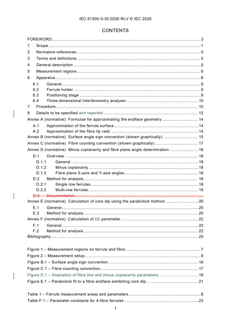
CONTENTS
FOREWORD . 3
1 Scope . 1
2 Normative references . 5
3 Terms and definitions . 5
4 General description . 5
5 Measurement regions . 6
6 Apparatus . 8
6.1 General . 8
6.2 Ferrule holder . 9
6.3 Positioning stage . 9
6.4 Three-dimensional interferometry analyser . 10
7 Procedure . 10
8 Details to be specified and reported . 12
Annex A (normative) Formulae for approximating the endface geometry . 14
A.1 Approximation of the ferrule surface . 14
A.2 Approximation of the fibre tip radii . 14
Annex B (normative) Surface angle sign convention (shown graphically) . 15
Annex C (normative) Fibre counting convention (shown graphically) . 17
Annex D (normative) Minus coplanarity and fibre plane angle determination . 18
D.1 Overview . 18
D.1.1 General . 18
D.1.2 Minus coplanarity . 18
D.1.3 Fibre plane X-axis and Y-axis angles . 18
D.2 Method for analysis . 18
D.2.1 Single row ferrules . 18
D.2.2 Multi-row ferrules . 19
D.3 Documentation .
Annex E (normative) Calculation of core dip using the paraboloid method . 20
E.1 General . 20
E.2 Method for analysis . 20
Annex F (normative) Calculation of GL parameter . 22
F.1 General . 22
F.2 Method for analysis . 22
Bibliography . 25
Figure 1 – Measurement regions on ferrule and fibre . 7
Figure 2 – Measurement setup. 9
Figure B.1 – Surface angle sign convention . 16
Figure C.1 – Fibre counting convention . 17
Figure D.1 – Illustration of fibre line and minus coplanarity parameters . 18
Figure E.1 – Paraboloid fit to a fibre endface exhibiting core dip . 21
Table 1 – Ferrule measurement areas and parameters . 8
Table F.1 – Parameter constants for 4-fibre ferrules . 23
Table F.2 – Parameter constants for 8-fibre ferrules . 24
Table F.3 – Parameter constants for 12-fibre ferrules . 24
INTERNATIONAL ELECTROTECHNICAL COMMISSION
____________
Fibre optic interconnecting devices and passive components -
Basic test and measurement procedures -
Part 3-30: Examinations and measurements -
Endface geometry of rectangular ferrule
FOREWORD
1) The International Electrotechnical Commission (IEC) is a worldwide organization for standardization comprising
all national electrotechnical committees (IEC National Committees). The object of IEC is to promote international
co-operation on all questions concerning standardization in the electrical and electronic fields. To this end and
in addition to other activities, IEC publishes International Standards, Technical Specifications, Technical Reports,
Publicly Available Specifications (PAS) and Guides (hereafter referred to as “IEC Publication(s)”). Their
preparation is entrusted to technical committees; any IEC National Committee interested in the subject dealt with
may participate in this preparatory work. International, governmental and non-governmental organizations liaising
with the IEC also participate in this preparation. IEC collaborates closely with the International Organization for
Standardization (ISO) in accordance with conditions determined by agreement between the two organizations.
2) The formal decisions or agreements of IEC on technical matters express, as nearly as possible, an international
consensus of opinion on the relevant subjects since each technical committee has representation from all
interested IEC National Committees.
3) IEC Publications have the form of recommendations for international use and are accepted by IEC National
Committees in that sense. While all reasonable efforts are made to ensure that the technical content of IEC
Publications is accurate, IEC cannot be held responsible for the way in which they are used or for any
misinterpretation by any end user.
4) In order to promote international uniformity, IEC National Committees undertake to apply IEC Publications
transparently to the maximum extent possible in their national and regional publications. Any divergence between
any IEC Publication and the corresponding national or regional publication shall be clearly indicated in the latter.
5) IEC itself does not provide any attestation of conformity. Independent certification bodies provide conformity
assessment services and, in some areas, access to IEC marks of conformity. IEC is not responsible for any
services carried out by independent certification bodies.
6) All users should ensure that they have the latest edition of this publication.
7) No liability shall attach to IEC or its directors, employees, servants or agents including individual experts and
members of its technical committees and IEC National Committees for any personal injury, property damage or
other damage of any nature whatsoever, whether direct or indirect, or for costs (including legal fees) and
expenses arising out of the publication, use of, or reliance upon, this IEC Publication or any other IEC
Publications.
8) Attention is drawn to the Normative references cited in this publication. Use of the referenced publications is
indispensable for the correct application of this publication.
9) IEC draws attention to the possibility that the implementation of this document may involve the use of (a)
patent(s). IEC takes no position concerning the evidence, validity or applicability of any claimed patent rights in
respect thereof. As of the date of publication of this document, IEC had not received notice of (a) patent(s), which
may be required to implement this document. However, implementers are cautioned that this may not represent
the latest information, which may be obtained from the patent database available at https://patents.iec.ch. IEC
shall not be held responsible for identifying any or all such patent rights.
This redline version of the official IEC Standard allows the user to identify the changes made
to the previous edition IEC 61300-3-30:2020. A vertical bar appears in the margin wherever a
change has been made. Additions are in green text, deletions are in strikethrough red text.
IEC 61300-3-30 has been prepared by subcommittee 86B: Fibre optic interconnecting devices
and passive components, of IEC technical committee 86: Fibre optics. It is an International
Standard.
This third edition cancels and replaces the second edition published in 2020. This edition
constitutes a technical revision.
This edition includes the following significant technical changes with respect to the previous
edition:
a) clarification of region diameter symbols;
b) introduction of x116 and x132 region of interest (ROI) to support MT-16 and MT-32 ferrule
types;
c) preparation of geometry limit (GL) parameter tables for 16-, 24- and 32-fibre ferrules;
d) clarification of the neighbouring fibres definition when computing adjacent height;
e) improvement of figures in Annexes.
The text of this International Standard is based on the following documents:
Draft Report on voting
86B/5224/FDIS 86B/5250/RVD
Full information on the voting for its approval can be found in the report on voting indicated in
the above table.
The language used for the development of this International Standard is English.
A list of all parts in the IEC 61300 series, published under the general title Fibre optic
interconnecting devices and passive components, can be found on the IEC website.
This document was drafted in accordance with ISO/IEC Directives, Part 2, and developed in
accordance with ISO/IEC Directives, Part 1 and ISO/IEC Directives, IEC Supplement, available
at www.iec.ch/members_experts/refdocs. The main document types developed by IEC are
described in greater detail at www.iec.ch/publications.
The committee has decided that the contents of this document will remain unchanged until the
stability date indicated on the IEC website under webstore.iec.ch in the data related to the
specific document. At this date, the document will be
– reconfirmed,
– withdrawn, or
– revised.
1 Scope
This part of IEC 61300 describes a method for measuring the endface geometry of rectangular
multifibre ferrules having an IEC defined optical interface. The primary attributes are fibre
position relative to the endface, either withdrawal or protrusion, endface angle relative to the
guide pin bores holes, fibre tip radii and core dip for multimode fibres.
2 Normative references
There are no normative references in this document.
3 Terms and definitions
No terms and definitions are listed in this document.
ISO and IEC maintain terminology databases for use in standardization at the following
addresses:
– IEC Electropedia: available at https://www.electropedia.org/
– ISO Online browsing platform: available at https://www.iso.org/obp
4 General description
Guide pin based multifibre connector plugs in IEC 61754-5 and all parts of IEC 61754-7 typically
have a rectangular endface with a long axis and a short axis. Ideally a flat polish is desired on
the endface with the fibres protruding slightly and all in the same plane to assure physical
contact of the fibre cores when two connectors are intermated. In practice, the endface typically
has two different curvatures across the surface along the long and short axis. Since mated
ferrules are aligned by pins in the guide holes, the endface of the ferrule shall be properly
oriented (SX and SY angles) with respect to the guide holes to achieve positive contact. The
endface angle SX in the long axis (X-axis) and the endface angle SY in the short axis (Y-axis)
(as defined in Annex B) are measured by finding the best fit plane (P ), based on a percentage
J
of the highest points in a specified region of interest. The highest points typically show the
greatest modulation from an interferometric standpoint. This allows for more robust
measurements and greater repeatability between different interferometers.
The angle of the best fit plane P is calculated by comparing it to the reference plane P which
J
is perpendicular to the averaged axis of each the guide holes. The height H (positive is a
protrusion) of the fibres is a planar height defined as the distance between the fibre endface
and the best fit plane. Core dip is only relevant to multimode fibres because the large core is
softer than the cladding of the fibre and tends to polish away faster. Core dip is calculated using
the paraboloid method described in Annex E.
One method is described for measuring the polish angle and fibre position for a single ferrule
multifibre connector by analysing the endface with a three-dimensional interferometry type
surface analyser.
5 Measurement regions
The following regions shall be defined on the ferrule endface.
a) Region of interest (ROI): the ROI is set on the ferrule surface and defined by a rectangular
region having a long axis (X-axis) of length, L, and a short axis (Y-axis) of height, H. The
region of interest is chosen to cover the intended contact zone of the ferrule endface when
the ferrules are mated. The region of interest shall be centred on the fibre array. See Figure
1. Refer to Table 1 for measurement areas to that shall be used for different connectors.
b) Extracting region: the extracting region, which includes the fibre endface regions and the
associated adhesive regions, is defined by circles having a diameter EØ , centred on each
E
fibre.
c) Averaging region: the averaging region is set on the fibre surfaces used to calculate the
fibre height, and is defined by a circle having a diameter FØ . The averaging region is the
F
same for single-mode (SM) fibres and multimode (MM) fibres.
d) Core dip region: the core dip region is set on the fibre surfaces used to calculate the fibre
core dip using the paraboloid method, and is defined by circles having a diameter CDØ ,
CDIP
centred on each fibre.
Additionally, core dip adjustment constant: the calculated core dip amplitude following the fit of
a paraboloid function to the fibre endface is adjusted by means of constant R .
Figure 1 – Measurement regions on ferrule and fibre
Table 1 – Ferrule measurement areas and parameters
Ferrule Descrip- Region of % top Next % Extracting Averaging Core dip Core dip
type tion interest ROI pixels top region region- fitting region adjustment
(variant excluded pixels (diameter SM+MM (diameter constant
(L × H
number) used (diameter R (see
EØ ) CDØ )
(X × Y)
E CDIP
a
FØ )
Annex E)
F
mm mm mm
mm mm × mm
x104 MT-04 2,900 × 0,675 3 20 0,140 0,05 0,03 0,03
Y
x108 MT-08 2,900 × 0,675 3 20 0,140 0,05 0,03 0,03
Y
x112 MT-12 2,900 × 0,675 3 20 0,140 0,05 0,03 0,03
Y
x124 MT-24 2,900 × 1,160 3 20 0,140 0,05 0,03 0,03
1116 16 3,900 × 0,675
Y
1124 MT-24 2,900 × 1,160 3 20 0,140 0,05 0,03 0,03
Y
1132 MT-32 3,900 × 1,160 3 20 0,140 0,05 0,03 0,03
Y
1002 MiniMT 0,900 × 0,675 3 20 0,140 0,05 0,03 0,03
Y
a
The x first digit defines 1 for polyphenylene sulfide (PPS) resin ferrule materials and 2 for thermoset materials;
the second digit represents 2,45 mm × 4,4 mm with 0 and 2,45 mm × 6,4 mm with 1; the last two digits
designates the number of fibres (see Table 1 of IEC 61755-3-31:2015, Table 1 of IEC 61755-3-32:2015
IEC PAS 63267-3-30:2021 and Table 1 of IEC PAS 63267-3-31:2020); and the subscript Y defines S for single-
mode fibres and M for multimode fibres.
6 Apparatus
6.1 General
The apparatus shown in Figure 2 consists of a positioning stage, a ferrule holder, an
interferometric video microscope, a PC-based fringe interpretation unit and a monitor to view
the ferrule endface interferogram and display the analysis results.
Figure 2 – Measurement setup
6.2 Ferrule holder
The ferrule holder is a suitable device to hold the ferrule in a fixed position, either vertical or
horizontal, or in a tilted position in the case of an angled ferrule type. Methods such as
mechanical alignment or interferometric measurement shall be used to determine the axis of
each guide hole and the average plane perpendicular to the guide hole axes. This plane shall
be considered as the reference plane P for reference to subsequent measurements calculations.
6.3 Positioning stage
The ferrule holder is fixed to the positioning stage, which shall enable the ferrule holder to be
moved to the appropriate position. The stage shall have sufficient rigidity to allow measurement
of the ferrule endface parameters within the required uncertainties detailed in 6.4.
6.4 Three-dimensional interferometry analyser
The three-dimensional interferometry analyser shall have the ability to measure the fibre heights
on the ferrule endface with an uncertainty better than within ±50 nm and the core dips with an
uncertainty better than within ±20 nm. The analyser shall consist of an interferometric video
microscope unit, a PC-based fringe interpretation (surface data processing) unit and a monitor.
The interferometric video microscope unit shall consist of an interference microscope, a phase
shift actuator, an image detector and an image acquisition and processing setup. The
interference microscope equipped with an objective is arranged so as to view the endface of
the ferrule.
The following parameters of the interference microscope shall be calibrated:
– optical magnification of the microscope;
– Z travel of the phase shift actuator;
– ferrule holder tilt angle in the case of an angled ferrule type.
The surface data processing unit shall be able to process the surface height information so as
to measure the following parameters:
a) ferrule surface x-angle SX (refer to Figure B.1 a) for the sign convention);
b) ferrule surface y-angle SY (refer to Figure B.1 b) for the sign convention);
c) fibre array minus coplanarity CF;
d) fibre plane x-angle GX (or fibre line if parts are single row);
e) fibre plane y-angle GY (if parts have more than one row);
f) fibre tip spherical radii RF (some conditions apply. See Clause 7, m). Refer to Figure C.1
for fibre counting convention);
g) core dip CDC (some conditions apply. See Clause 7, i). Refer to Figure C.1 for fibre
DIP
counting convention);
h) geometry limit GL (refer to Annex F for the calculation method);
i) ferrule surface x-radius RX (along the Z-axis with main curvature around X-axis);
j) ferrule surface y-radius RY (along the Z-axis with main curvature around Y-axis);
k) fibre height H (refer to Figure C.1 for fibre counting convention);
l) adjacent fibre height differential HA (refer to Figure C.1 for fibre counting convention).
The monitor shall display the measured and calculated surface profiles along each axis.
7 Procedure
The following procedure shall be used for this measurement.
a) Affix the ferrule in the ferrule holder so that the endface is held sufficiently steady with
respect to the interferometer.
b) Focus either the microscope or the sample, or both until the fringes are in position to
scan the surface.
c) Map the surface of the ferrule.
To create data set "A", use only
the pixels contained within the
ROI.
d) Create data set "B" by removing
the extracting regions around the
fibres.
e) Create surface "C" by fitting a bi-
parabolic curve to data set "B"
(see Annex A for. The curve
fitting routine) shall be performed
as specified in Annex A.
f) Create data set "D" by
subtracting surface "C" from data
set "B"
g) Create data set "E" by removing
the highest 3 % of all pixels in
data set "D". This removes any
small points that are extremely
high compared to the others. It is
assumed these will break off
when the connectors contact.
NOTE Points are selected as a percentage of the total area which includes pixels for which heights could
not cannot be determined.
h) Create data set "F" by identifying
the highest 20 % of all pixels in
data set "E".
NOTE Points are selected as a percentage of the total area which includes pixels for which heights could
not cannot be determined.
i) Create data set "G" by
eliminating all pixels from data
set "A" except for those identified
in data set "F".
j) Fit a least squares plane P to
J
data set "G" and use the plane to
calculate SX and SY angles using
plane P as a reference (see
Annex B for end face. The
endface angle sign conventions)
shall be in accordance with
Annex B. "Add" the extracting
regions back in.
Calculate the fibre heights H as the distance normal to plane P at the corresponding fibre
J
centre locations (see Annex C for. The fibre counting conventions) shall be in accordance
with Annex C. Calculate the adjacent fibre height differential HA for each fibre. For a given
fibre, HA is the largest height difference with the two immediately neighbouring fibres, i.e.
the fibres located on the left and right (single row ferrule case) or four as well as above
and below (multi-row ferrule case neighbour fibres).
k) Fit a bi-parabolic curve to data set "G" (see Annex A for. The curve fitting routine) shall
be performed as specified in Annex A. Calculate the ferrule surface RX and RY radii
values.
l) determine the core dip (for multi-mode and singlemode fibres) CD of each fibre. See
Annex E for a detailed procedure. Skip this step for single-mode fibres. For multimode
fibres, determine the core dip C of each fibre. The calculation method shall be in
DIP
accordance with Annex E.
If CDC of a given fibre is positive and larger than 10 nm, report CDC and skip step
DIP DIP
m) for that given fibre.
If CDC of a given fibre is negative or smaller than or equal to 10 nm, do not report
DIP
CDC for that given fibre and proceed to step m).
DIP
m) Determine radius RF of a given fibre tip. This is accomplished by fitting a sphere to the
surface points of the averaging region of the fibre (see Annex A for the curve fitting
routine) shall be performed as specified in Annex A). The radius of the fitted sphere is
then taken as the fibre tip radius.
n) Determine the minus coplanarity CF. See Annex D for a detailed procedure. The
procedure shall be in accordance with Annex D. Use the fibre plane to calculate GX and
GY angles using the average of the guide pin bore holes axes as a reference (see
Annex B for end face. The endface angle sign conventions) shall be in accordance with
Annex B.
o) If CD is negative or smaller than 10 nm C was reported for more than 50 % or fewer
DIP
of the fibres, determine the geometry limit GL using the median value of the RF values
of the fibres which exhibited a negative CD C . See Annex F. The calculation method
DIP
shall be in accordance with Annex F.
8 Details to be specified and reported
The following items shall be specified for this measurement:
– type of interferometry;
– nominal angle of tilt, for example physical contact (PC)/angled PC (APC);
– any deviation from this method;
– Measurement uncertainty.
The following details, as applicable, shall be specified in the relevant specification and shall be
reported in the test report.
a) DUT characteristics:
1) nominal angle of tilt, for example physical contact (PC)/angled PC (APC);
2) ferrule type (see Table 1).
b) Measurement equipment specification and setup (see Clause 6):
1) type of interferometry.
c) Measurement uncertainty (see 6.4).
d) Final examinations, measurements and calculations, and performance requirements (see
Clause 7):
1) ferrule surface x-angle SX;
2) ferrule surface y-angle SY;
3) fibre array minus coplanarity CF;
4) fibre plane x-angle GX;
5) fibre plane y-angle GY;
6) fibre tip spherical radii RF;
7) core dip C ;
DIP
8) geometry limit GL (see Annex F);
9) ferrule surface x-radius RX;
10) ferrule surface y-radius RY;
11) fibre height H;
12) adjacent fibre height differential HA.
e) Deviations from this test procedure.
Annex A
(normative)
Formulae for approximating the endface geometry
A.1 Approximation of the ferrule surface
The ideal ferrule surface being calculated for multifibre connectors is described by
Formula (A.1):
2 2
XY
(A.1)
Z=− − − S × X+ S ×+YC
X Y
22RR
XY
The coefficients for this formula which result in the best fitting ideal surface are found using a
least squares approximation. R and R are the radii of curvature for a bi-parabolic surface
X Y
along the X and Y axes: S provides the X-axis surface angle value, while S provides the Y-axis
X Y
surface angle value. C is the constant that identifies the relative height. By setting the squared
terms to zero, a planar surface is defined.
A.2 Approximation of the fibre tip radii
The ideal surface being calculated for each fibre tip is a sphere and is described by
Formula (A.2):
22 2
(A.2)
X− X + Y− Y + Z− Z =RF
( ) ( ) ( )
00 0
The coefficients for this formula which result in the best fitting ideal surface are found using a
least squares approximation. 𝑅𝑅𝑅𝑅 is the radius of curvature of the fitted sphere. 𝑋𝑋 , 𝑌𝑌 and 𝑍𝑍 are
0 0 0
the coordinates of the centre of the fitted sphere, which may is not necessarily be centred on
the fibre core (apex offset).
Annex B
(normative)
Surface angle sign convention (shown graphically)
Annex B describes surface angle sign convention graphically. Figure B.1 a) shows the x-axis
view, and Figure B.1 b) shows the y-axis view.
a) X-axis view
b) Y-axis view
NOTE 1 The optical interface coordinate system is established with an X-axis, which passes through the guide
hole centres, a perpendicular Y-axis that passes through the midpoint of the line connecting the guide hole centres,
and an orthogonal Z-axis pointing away from the ferrule.
NOTE 2 The adhesive window is an example of a keying feature.
Figure B.1 – Surface angle sign convention
Annex C
(normative)
Fibre counting convention (shown graphically)
Annex C describes fibre counting convention as shown in Figure C.1.
NOTE 1 Fibre counting convention is applicable for all variants: flat or angled, single or double row, and lower or
higher fibre count (e.g. 4, 8, 16 or 32 fibres).
NOTE 2 The adhesive window is an example of a keying feature.
Figure C.1 – Fibre counting convention
Annex D
(normative)
Minus coplanarity and fibre plane angle determination
D.1 Overview
D.1.1 General
This annex describes three additional parameters to that shall be calculated and reported for
measurements made in accordance with this standard.
D.1.2 Minus coplanarity
Minus coplanarity is the greatest parallel offset between the best fit plane (or line in the case
of single row ferrules as illustrated in Figure D.1) of the fibre ends (the average elevation of the
averaging regions) and a fibre end below that plane (or line).
Figure D.1 – Illustration of fibre line and minus coplanarity parameters
D.1.3 Fibre plane X-axis and Y-axis angles
The relative tilt of the best fit plane of D.1.2 relative to the average of the guide pin bore holes
axes.
D.2 Method for analysis
D.2.1 Single row ferrules
Create an array of X and Z values where X is the fibre location and Z is the fibre height
determined in Clause 7, j). Fit a least squares line z(X) to this data. Calculate the array minus
coplanarity CF using Formula (D.1):
CF max(z X− Z )
( ) (D.1)
ii
where z(X ) − Z represents the deviation of each fibre tip, i, from the fibre line.
i i
Calculate the X-axis GX angle of the least squares fit line (the fibre line) using a line
perpendicular to the guide pin bores holes axes as a reference.
=
D.2.2 Multi-row ferrules
Create an array of X, Y and Z values where 𝑋𝑋 and 𝑌𝑌 are the fibre locations and 𝑍𝑍 is the fibre
height determined in Clause 7, j). Fit a least squares plane 𝑧𝑧(𝑋𝑋,𝑌𝑌) to this data. Calculate the
array minus coplanarity using Formula (D.2):
CF max(z X ,Y− Z )
( )
ii i (D.2)
where z(X ,Y ) − Z represents the deviation of each fibre tip, 𝑖𝑖, from the fibre line.
i i i
Calculate the X-axis GX and Y-axis GY angles of the least squares fit plane (the fibre plane)
using a plane perpendicular to the guide pin bores holes axes as a reference.
D.3 Documentation
In addition to the requirements of Clause 8, report:
– minus coplanarity;
– x-axis angle G of the fibre line (or plane if parts have more than one row);
X
– y-axis angle G of the fibre plane (if parts have more than one row).
Y
=
Annex E
(normative)
Calculation of core dip using the paraboloid method
E.1 General
Annex E describes the core dip parameter to that shall be calculated and reported for
measurements made in accordance with this document. Core dip is a measurement of the fibre
core elevation compared to the cladding elevation at its endface (see Figure E.1).
E.2 Method for analysis
Fit a paraboloid function to each fibre endface surface points located inside zone CD a
paraboloid function of type core dip region using Formula (E.1):
(E.1)
Z AX+ BY++CX DY+ E
The coefficients for this formula which result in the best fitting ideal surface are found using a
least squares approximation. Figure E.1 shows the fitting manner graphically.
For each fibre, the core dip CDC is then calculated using Formula (E.2):
DIP
CD (A+ B)R / 2
(E.2)
C A+ BR / 2
( ) (E.2)
DIP 1
NOTE See Table 1 for the value of R .
=
=
=
Figure E.1 – Paraboloid fit to a fibre endface exhibiting core dip
Annex F
(normative)
Calculation of GL parameter
F.1 General
Annex F describes the GL parameter to that shall be calculated and reported for measurements
made in accordance with this standard. GL is used to quantitatively assess the acceptability of
an endface geometry.
F.2 Method for analysis
For single row ferrules, this term is a calculated merit function, which relates x-slope angle, SX,
minus coplanarity, CF, and fibre tip radii, RF. There are 30 constants that define the relationship
among these parameters. When fully expanded, the function takes the form of is as defined in
Formula (F.1):
A A
01qq
− − n
q
RF RF −
(A − A )⋅e + A − ()A −⋅Ae + A ⋅
01 00 00 11 10 10 RF
− nn−⋅e +n ⋅ S
( )
10 0 X
GL()S ,CF ,RF ⋅−e 1 +
X
A
qq
−
RF
− ()A −⋅A e + A ⋅CF
qq10 q0 A
1q
−
RF
e + (A −⋅A ) e + A
11 10 10
B
qq
−
RF
− ()B −B ⋅e +B ⋅CF
BB qq10 q0 B
01qq 1q
−− −
RF RF RF
(B − B )⋅e + B − ()BB−⋅e + B ⋅e + ( BB−⋅) e + B
01 00 00 11 10 10 11 10 10
⋅+S
X
B
1q
−
RF
e + B
10
p
q
−
RF
− ()p− p ⋅e + p ⋅CF
1 0 0
C D
q q
− −
RF RF
(CC−⋅) e + C ⋅e −+1( D − D )⋅e + D ⋅CF
10 0 10 0
(F.1)
=
A A
01qq
− −
RF RF
( A − A )× e + A − ( AA−×) e + A
01 00 00 11 10 10
GL(SXC,,FRF)=
A
qq
−
RF
− A −×A e + A ×CF
( )
qq10 q0 A
1q
−
RF
×e +−AA × e + A
( )
11 10 10
B
1q
n B −
q 0q
− RF
B − B ×−e + B − BB− × e + B
( ) ( )
RF 01 00 00 11 10 10
− (n−n )×e +n × SK
RF
(F.1)
×−e 1 +×
B
qq
−
RF
− B −×B e +B ⋅CF
( )
qq10 q0
B
1q
−
RF
×e +−BB × e + B
( )
11 10 10
p
q
−
RF
− ( pp−×) e + p ×CF
C 1 0 0 D
q q
− −
RF RF
SX + C −×C e + C × e −+1 D − D × e + D × CF
( ) ( )
10 0 10 0
For incorporation with endface inspection algorithms, this function can also be expressed with
Unicode text:
GL(S_x,CF,RF) = [(((A_01 – A_00) · e^(–A_0q/RF) + A_00) – ((A_11 – A_10) ·
e^(–A_1q/RF) + A_10)) · e^(–((A_q1 – A_q0) · e^(–A_qq/RF) + A_q0) · CF) +
(A_11 – A_10) · e^(–A_1q/RF) + A_10] · (e^(–((n_1 – n_0) · e^(–n_q/RF) + n_0) ·
|S_x|) – 1) + [(((B_01 – B_00) · e^(–B_0q/RF) + B_0) – ((B_11 – B_10) ·
e^(–B_1q/RF) + B_10)) · e^(–((B_q1 – B_q0) · e^(–B_qq/RF) + B_q0) · CF) + (B_11 – B_10) ·
e^(–B_1q/RF) + B_10] · |S_x| + ((C_1 – C_0) · e^(–C_q/RF) + C_0) · (e^(–((p_1 – p_0) ·
e^(–p_q/RF) + p_0) · CF) – 1) + ((D_1 – D_0) · e^(–D_q/RF) + D_0) · CF
𝐺𝐺𝐺𝐺(𝑆𝑆𝑋𝑋,𝐶𝐶𝑅𝑅,𝑅𝑅𝑅𝑅) = [(((𝐴𝐴_01−𝐴𝐴_00 )∙𝑒𝑒^(−𝐴𝐴_0𝑞𝑞/𝑅𝑅𝑅𝑅) +𝐴𝐴_00 )− ((𝐴𝐴_11−𝐴𝐴_10 )∙𝑒𝑒^(−𝐴𝐴_1𝑞𝑞/𝑅𝑅𝑅𝑅)
+𝐴𝐴_10 ) )∙𝑒𝑒^(−((𝐴𝐴_𝑞𝑞1−𝐴𝐴_𝑞𝑞0 )∙𝑒𝑒^(−𝐴𝐴_𝑞𝑞𝑞𝑞/𝑅𝑅𝑅𝑅) +𝐴𝐴_𝑞𝑞0 )∙𝐶𝐶𝑅𝑅) + (𝐴𝐴_11−𝐴𝐴_10 )
∙𝑒𝑒^(−𝐴𝐴_1𝑞𝑞/𝑅𝑅𝑅𝑅) +𝐴𝐴_10 ]∙ (𝑒𝑒^(−((𝑛𝑛_1−𝑛𝑛_0 )∙𝑒𝑒^(−𝑛𝑛_𝑞𝑞/𝑅𝑅𝑅𝑅) +𝑛𝑛_0 )∙ |𝑆𝑆𝑋𝑋| )− 1)
+ [(((𝐵𝐵_01−𝐵𝐵_00 )∙𝑒𝑒^(−𝐵𝐵_0𝑞𝑞/𝑅𝑅𝑅𝑅) +𝐵𝐵_00 )− ((𝐵𝐵_11−𝐵𝐵_10 )∙𝑒𝑒^(−𝐵𝐵_1𝑞𝑞/𝑅𝑅𝑅𝑅)
+𝐵𝐵_10 ) )∙𝑒𝑒^(−((𝐵𝐵_𝑞𝑞1−𝐵𝐵_𝑞𝑞0 )∙𝑒𝑒^(−𝐵𝐵_𝑞𝑞𝑞𝑞/𝑅𝑅𝑅𝑅) +𝐵𝐵_𝑞𝑞0 )∙𝐶𝐶𝑅𝑅) + (𝐵𝐵_11−𝐵𝐵_10 )
∙𝑒𝑒^(−𝐵𝐵_1𝑞𝑞/𝑅𝑅𝑅𝑅) +𝐵𝐵_10 ]∙ |𝑆𝑆𝑋𝑋| + ((𝐶𝐶_1−𝐶𝐶_0 )∙𝑒𝑒^(−𝐶𝐶_𝑞𝑞/𝑅𝑅𝑅𝑅) +𝐶𝐶_0 )∙ (𝑒𝑒^(−((𝑝𝑝_1
−𝑝𝑝_0 )∙𝑒𝑒^(−𝑝𝑝_𝑞𝑞/𝑅𝑅𝑅𝑅) +𝑝𝑝_0 )∙𝐶𝐶𝑅𝑅)− 1) + ((𝐷𝐷_1−𝐷𝐷_0 )∙𝑒𝑒^(−𝐷𝐷_𝑞𝑞/𝑅𝑅𝑅𝑅) +𝐷𝐷_0 )∙𝐶𝐶𝑅𝑅
The parameter constants are dependent on the number of fibres as summarized in Table F.1 to
Table F.3 .
Table F.1 – Parameter constants for 4-fibre ferrules
A A A B B B
C D N p
0 1 q 0 1 q
f
2,334 1,049 0,000 20,930 0,000 0,402 2,470 12,402 0,000 4,296
f
0,000 0,000 4,907 84,717 84,717 139,916 0,000 18,072 19,663 27,813
f
6,676 8,306 0,000 0,393 0,000 12,201 3,575 2,135 0,000 7,108
q
___________
GL and coplanarity parameters are not defined for ferrule type 1002.
Table F.2 – Parameter constants for 8-fibre ferrules
A A A B B B
C D N p
0 1 q 0 1 q
f
3,117 -0,372 0,000 122,558 0,000 -0,439 2,109 15,227 0,000 6,253
f
0,000 0,000 4,779 151,602 151,602 -0,441 0,000 27,043 14,698 15,980
f
5,504 56,276 0,000 1,095 0,000 -4,844 10,334 2,216 0,000 7,994
q
Table F.3 – Parameter constants for 12-fibre ferrules
A A A B B B
C D N p
0 1 q 0 1 q
f
0,563 -0,313 0,000 120,677 0,000 0,000 3,452 20,367 0,000 4,874
f
0,000 0,000 10,082 148,540 148,540 2,481 0,000 36,545 69,299 8,685
f
110,476 78,066 0,000 3,129 0,000 0,000 11,688 1,800 0,000 5,860
q
NOTE OtherGL is not defined for fibre counts that are currently under development.
Bibliography
IEC 61300 (all parts), Fibre optic interconnecting devices and passive components - Basic test
and measurement procedures
IEC 61755-3-31:2015, Fibre optic interconnecting devices and passive components - Connector
optical interfaces - Part 3-31: Connector parameters of non-dispersion shifted single mode
physically contacting fibres - Angled polyphenylene sulphide rectangular ferrules
IEC 61755-3-32:2015, Fibre optic interconnecting devices and passive components - Connector
optical interfaces - Part 3-32: Connector parameters of non-dispersion shifted single mode
physically contacting fibres - Angled thermoset epoxy rectangular ferrules
IEC PAS 63267-3-30:2021, Fibre optic interconnecting devices and passive components - Fibre
optic connector optical interfaces - Part 3-30: End face geometry - Angled PC end face PPS
rectangular ferrule multimode A1b fibres
IEC PAS 63267-3-31:2020, Fibre optic interconnecting devices and passive components - Fibre
optic connector optical interfaces - Part 3-31: End face geometry - Flat PC PPS rectangular
ferrule multimode fibres
IEC 61754-5:2005, Fibre optic connector interfaces - Part 5: Type MT connector family
IEC 61754-7 (all parts), Fibre optic interconnecting devices and passive components - Fibre
optic connector interfaces - Type MPO connector family
___________
IEC 61300-3-30 ®
Edition 3.0 2026-07
INTERNATIONAL
STANDARD
Fibre optic interconnecting devices and passive components - Basic test and
measurement procedures -
Part 3-30: Examinations and measurements - Endface geometry of rectangular
ferrule
ICS 33.180.20 ISBN 978-2-8327-1373-0
CONTENTS
FOREWORD . 3
1 Scope . 5
2 Normative references . 5
3 Terms and definitions . 5
4 General description . 5
5 Measurement regions . 6
6 Apparatus . 7
6.1 General . 7
6.2 Ferrule holder . 8
6.3 Positioning stage . 8
6.4 Three-dimensional interferometry analyser . 8
7 Procedure . 9
8 Details to be specified and reported . 11
Annex A (normative) Formulae for approximating the endface geometry . 12
A.1 Approximation of the ferrule surface . 12
A.2 Approximation of the fibre tip radii . 12
Annex B (normative) Surface angle sign convention (shown graphically) . 13
Annex C (normative) Fibre counting convention (shown graphically) . 14
Annex D (normative) Minus coplanarity and fibre plane angle determination . 15
D.1 Overvie
...
IEC 61300-3-30 ®
Edition 3.0 2026-07
NORME
INTERNATIONALE
Dispositifs d'interconnexion et composants passifs fibroniques - Procédures
fondamentales d'essais et de mesures -
Partie 3-30: Examens et mesures - Géométrie de la surface de terminaison de la
férule rectangulaire
ICS 33.180.20 ISBN 978-2-8327-1373-0
Droits de reproduction réservés. Sauf indication contraire, aucune partie de cette publication ne peut être reproduite ni
utilisée sous quelque forme que ce soit et par aucun procédé, électronique ou mécanique, y compris la photocopie et
les microfilms, sans l'accord écrit de l'IEC ou du Comité national de l'IEC du pays du demandeur. Si vous avez des
questions sur le copyright de l'IEC ou si vous désirez obtenir des droits supplémentaires sur cette publication, utilisez
les coordonnées ci-après ou contactez le Comité national de l'IEC de votre pays de résidence.
IEC Secretariat Tel.: +41 22 919 02 11
3, rue de Varembé info@iec.ch
CH-1211 Geneva 20 www.iec.ch
Switzerland
A propos de l'IEC
La Commission Electrotechnique Internationale (IEC) est la première organisation mondiale qui élabore et publie des
Normes internationales pour tout ce qui a trait à l'électricité, à l'électronique et aux technologies apparentées.
A propos des publications IEC
Le contenu technique des publications IEC est constamment revu. Veuillez vous assurer que vous possédez l’édition la
plus récente, un corrigendum ou amendement peut avoir été publié.
Recherche de publications IEC - IEC Products & Services Portal - products.iec.ch
webstore.iec.ch/advsearchform Découvrez notre puissant moteur de recherche et consultez
La recherche avancée permet de trouver des publications gratuitement tous les aperçus des publications, symboles
IEC en utilisant différents critères (numéro de référence, graphiques et le glossaire. Avec un abonnement, vous aurez
texte, comité d’études, …). Elle donne aussi des toujours accès à un contenu à jour adapté à vos besoins.
informations sur les projets et les publications remplacées
ou retirées. Electropedia - www.electropedia.org
Le premier dictionnaire d'électrotechnologie en ligne au
IEC Just Published - webstore.iec.ch/justpublished monde, avec plus de 22 500 articles terminologiques en
Restez informé sur les nouvelles publications IEC. Just anglais et en français, ainsi que les termes équivalents
dans 25 langues additionnelles. Egalement appelé
Published détaille les nouvelles publications parues.
Disponible en ligne et une fois par mois par email. Vocabulaire Electrotechnique International (IEV) en ligne.
Service Clients - webstore.iec.ch/csc
Si vous désirez nous donner des commentaires sur cette
publication ou si vous avez des questions contactez-
nous: sales@iec.ch.
SOMMAIRE
AVANT-PROPOS . 3
1 Domaine d'application . 5
2 Références normatives . 5
3 Termes et définitions . 5
4 Description générale . 5
5 Régions de mesurage . 6
6 Appareillage . 7
6.1 Généralités . 7
6.2 Support de férule . 8
6.3 Étage de positionnement . 8
6.4 Analyseur d’interférométrie tridimensionnelle . 8
7 Mode opératoire . 9
8 Informations détaillées à spécifier et à faire figurer dans le rapport . 11
Annexe A (normative) Formules d’approximation de la géométrie de la surface de
terminaison . 12
A.1 Approximation de la surface de la férule . 12
A.2 Approximation des rayons des pointes des fibres . 12
Annexe B (normative) Convention de signe des angles de surface (représentation
graphique) . 13
Annexe C (normative) Convention de comptage des fibres (représentation graphique) . 14
Annexe D (normative) Détermination de la coplanarité négative et des angles du plan
de fibre . 15
D.1 Vue d'ensemble . 15
D.1.1 Généralités . 15
D.1.2 Coplanarité négative . 15
D.1.3 Angles du plan de fibre par rapport à l’axe X et à l’axe Y . 15
D.2 Méthode pour l'analyse . 15
D.2.1 Férules à rangée unique . 15
D.2.2 Férules à rangées multiples . 16
Annexe E (normative) Calcul de la dépression du cœur à l’aide de la méthode
paraboloïde . 17
E.1 Généralités . 17
E.2 Méthode pour l'analyse . 17
Annexe F (normative) Calcul du paramètre GL . 19
F.1 Généralités . 19
F.2 Méthode pour l'analyse . 19
Bibliographie . 21
Figure 1 – Régions de mesurage sur la férule et la fibre . 6
Figure 2 – Configuration du mesurage . 7
Figure B.1 – Convention de signe des angles de surface . 13
Figure C.1 – Convention de comptage des fibres . 14
Figure D.1 – Représentation des paramètres de ligne de fibre et de coplanarité
négative . 15
Figure E.1 – Ajustement paraboloïde à une surface de terminaison de fibre présentant
une dépression du cœur . 18
Tableau 1 – Zones et paramètres de mesurage des férules . 7
Tableau F.1 – Constantes de paramètres pour les férules à 4 fibres . 20
Tableau F.2 – Constantes de paramètres pour les férules à 8 fibres . 20
Tableau F.3 – Constantes de paramètres pour les férules à 12 fibres . 20
COMMISSION ÉLECTROTECHNIQUE INTERNATIONALE
____________
Dispositifs d'interconnexion et composants passifs fibroniques -
Procédures fondamentales d'essais et de mesures -
Partie 3-30: Examens et mesures -
Géométrie de la surface de terminaison de la férule rectangulaire
AVANT-PROPOS
1) La Commission Électrotechnique Internationale (IEC) est une organisation mondiale de normalisation composée
de l'ensemble des comités électrotechniques nationaux (Comités nationaux de l’IEC). L’IEC a pour objet de
favoriser la coopération internationale pour toutes les questions de normalisation dans les domaines de
l'électricité et de l'électronique. À cet effet, l’IEC – entre autres activités – publie des Normes internationales,
des Spécifications techniques, des Rapports techniques, des Spécifications accessibles au public (PAS) et des
Guides (ci-après dénommés "Publication(s) de l’IEC"). Leur élaboration est confiée à des comités d'études, aux
travaux desquels tout Comité national intéressé par le sujet traité peut participer. Les organisations
internationales, gouvernementales et non gouvernementales, en liaison avec l’IEC, participent également aux
travaux. L’IEC collabore étroitement avec l'Organisation Internationale de Normalisation (ISO), selon des
conditions fixées par accord entre les deux organisations.
2) Les décisions ou accords officiels de l’IEC concernant les questions techniques représentent, dans la mesure du
possible, un accord international sur les sujets étudiés, étant donné que les Comités nationaux de l’IEC intéressés
sont représentés dans chaque comité d’études.
3) Les Publications de l’IEC se présentent sous la forme de recommandations internationales et sont agréées
comme telles par les Comités nationaux de l’IEC. Tous les efforts raisonnables sont entrepris afin que l’IEC
s'assure de l'exactitude du contenu technique de ses publications; l’IEC ne peut pas être tenue responsable de
l'éventuelle mauvaise utilisation ou interprétation qui en est faite par un quelconque utilisateur final.
4) Dans le but d'encourager l'uniformité internationale, les Comités nationaux de l’IEC s'engagent, dans toute la
mesure possible, à appliquer de façon transparente les Publications de l’IEC dans leurs publications nationales
et régionales. Toutes divergences entre toutes Publications de l’IEC et toutes publications nationales ou
régionales correspondantes doivent être indiquées en termes clairs dans ces dernières.
5) L’IEC elle-même ne fournit aucune attestation de conformité. Des organismes de certification indépendants
fournissent des services d'évaluation de conformité et, dans certains secteurs, accèdent aux marques de
conformité de l’IEC. L’IEC n'est responsable d'aucun des services effectués par les organismes de certification
indépendants.
6) Tous les utilisateurs doivent s'assurer qu'ils sont en possession de la dernière édition de cette publication.
7) Aucune responsabilité ne doit être imputée à l’IEC, à ses administrateurs, employés, auxiliaires ou mandataires,
y compris ses experts particuliers et les membres de ses comités d'études et des Comités nationaux de l’IEC,
pour tout préjudice causé en cas de dommages corporels et matériels, ou de tout autre dommage de quelque
nature que ce soit, directe ou indirecte, ou pour supporter les coûts (y compris les frais de justice) et les dépenses
découlant de la publication ou de l'utilisation de cette Publication de l’IEC ou de toute autre Publication de l’IEC,
ou au crédit qui lui est accordé.
8) L'attention est attirée sur les références normatives citées dans cette publication. L'utilisation de publications
référencées est obligatoire pour une application correcte de la présente publication.
9) L'IEC attire l'attention sur le fait que la mise en application du présent document peut entraîner l'utilisation d'un
ou de plusieurs brevets. L'IEC ne prend pas position quant à la preuve, à la validité et à l'applicabilité de tout
droit de brevet revendiqué à cet égard. À la date de publication du présent document, l'IEC n'a pas reçu
notification qu'un ou plusieurs brevets pouvaient être nécessaires à sa mise en application. Toutefois, il y a lieu
d'avertir les responsables de la mise en application du présent document que des informations plus récentes
sont susceptibles de figurer dans la base de données de brevets, disponible à l'adresse https://patents.iec.ch.
L'IEC ne saurait être tenue pour responsable de ne pas avoir identifié de tels droits de brevets.
L'IEC 61300-3-30 a été établie par le sous-comité 86B: Dispositifs d'interconnexion et
composants passifs fibroniques, du comité d'études 86 de l'IEC: Fibronique. Il s'agit d'une
Norme internationale.
Cette troisième édition annule et remplace la deuxième édition parue en 2020. Cette édition
constitue une révision technique.
Cette édition inclut les modifications techniques significatives suivantes par rapport à l'édition
précédente:
a) clarification des symboles pour le diamètre des différentes régions;
b) introduction de la région d'intérêt (ROI, region of interest) x116 et x132 pour prendre en
charge les types de férules MT-16 et MT-32;
c) préparation de tableaux de paramètres de limite de géométrie (GL, geometry limit) pour les
férules à 16, 24 et 32 fibres;
d) clarification de la définition des fibres adjacentes pour le calcul du différentiel de hauteur
entre fibres adjacentes;
e) amélioration des figures des Annexes.
Le texte de cette Norme internationale est issu des documents suivants:
Projet Rapport de vote
86B/5224/FDIS 86B/5250/RVD
Le rapport de vote indiqué dans le tableau ci-dessus donne toute information sur le vote ayant
abouti à son approbation.
La langue employée pour l'élaboration de cette Norme internationale est l'anglais.
Une liste de toutes les parties de la série IEC 61300, publiées sous le titre général Dispositifs
d’interconnexion et composants passifs fibroniques, se trouve sur le site web de l’IEC.
Ce document a été rédigé selon les Directives ISO/IEC, Partie 2, il a été développé selon les
Directives ISO/IEC, Partie 1 et les Directives ISO/IEC, Supplément IEC, disponibles sous
www.iec.ch/members_experts/refdocs. Les principaux types de documents développés par
l'IEC sont décrits plus en détail sous www.iec.ch/publications.
Le comité a décidé que le contenu de ce document ne sera pas modifié avant la date de stabilité
indiquée sur le site web de l'IEC sous webstore.iec.ch dans les données relatives au document
recherché. À cette date, le document sera
– reconduit,
– supprimé, ou
– révisé.
1 Domaine d'application
La présente partie de l’IEC 61300 décrit une méthode de mesurage applicable à la géométrie
de la surface de terminaison des férules rectangulaires multifibres dont l’interface optique est
définie par l’IEC. Les attributs primaires sont la position de la fibre par rapport à la surface de
terminaison, l’angle de la surface de terminaison par rapport aux trous de guidage, les rayons
des pointes des fibres et la dépression du cœur pour les fibres multimodales.
2 Références normatives
Le présent document ne contient aucune référence normative.
3 Termes et définitions
Aucun terme n’est défini dans le présent document.
L'ISO et l'IEC tiennent à jour des bases de données terminologiques destinées à être utilisées
en normalisation, consultables aux adresses suivantes:
– IEC Electropedia: disponible à l'adresse https://www.electropedia.org/
– ISO Online browsing platform: disponible à l’adresse https://www.iso.org/obp
4 Description générale
Les fiches de connecteurs multifibres à broche de guidage de l'IEC 61754-5 et de toutes les
parties de l'IEC 61754-7 comportent généralement une surface de terminaison rectangulaire
avec un axe long et un axe court. Dans l’idéal, un polissage plat est souhaité sur la surface de
terminaison, avec une légère excroissance des fibres, toutes dans le même plan, pour assurer
un contact physique des cœurs des fibres lorsque deux connecteurs sont accouplés.
En pratique, la surface de terminaison présente généralement deux courbures différentes sur
sa surface, le long de l’axe long et de l’axe court. Étant donné que les férules accouplées sont
alignées par des broches dans les trous de guidage, la surface de terminaison de la férule doit
être orientée de façon appropriée (angles SX et SY) par rapport aux trous de guidage pour
permettre un contact positif. L'angle SX de la surface de terminaison sur l'axe long (axe X) et
l'angle SY de la surface de terminaison sur l'axe court (axe Y) (tels qu'ils sont définis en
Annexe B) sont mesurés en déterminant le plan du meilleur ajustement (P ), à partir d’un
J
pourcentage des points les plus élevés dans une région d’intérêt spécifiée. Les points les plus
élevés présentent généralement la modulation la plus grande en matière d’interférométrie. Cela
permet des mesurages plus robustes et une répétabilité plus importante entre différents
interféromètres.
L’angle du plan du meilleur ajustement P est calculé en le comparant avec le plan de
J
référence P perpendiculaire à l’axe moyenné des trous de guidage. La hauteur H des fibres (si
elle est positive, elle désigne une excroissance) est une hauteur plane définie comme la
distance entre la surface de terminaison de la fibre et le plan du meilleur ajustement. La
dépression du cœur est seulement pertinente pour les fibres multimodales, car un cœur de plus
grand diamètre est plus tendre que la gaine de la fibre et a tendance à s’user plus vite. La
dépression du cœur est calculée à l’aide de la méthode paraboloïde décrite à l'Annexe E.
Une méthode est décrite pour mesurer l’angle de la face polie et la position de la fibre d’un
connecteur multifibres à férule unique. Elle consiste à analyser la surface de terminaison avec
un analyseur de surface de type interférométrie tridimensionnelle.
5 Régions de mesurage
Les régions suivantes doivent être définies sur la surface de terminaison de la férule.
a) Région d’intérêt (ROI): la ROI est positionnée sur la surface de la férule et est définie par
une région rectangulaire qui comporte un axe long (axe X) et un axe court (axe Y). La région
d'intérêt est choisie de façon à couvrir la zone de contact prévue de la surface de
terminaison de la férule lorsque les férules sont accouplées. La région d'intérêt doit être
centrée sur le groupe de fibres. Voir la Figure 1. Se reporter au Tableau 1 pour les zones
de mesurage qui doivent être utilisées pour différents connecteurs.
b) Région d’extraction: la région d’extraction, qui inclut les régions des surfaces de terminaison
des fibres et les régions adhésives associées, est définie par des cercles de diamètre Ø ,
E
centrés sur chaque fibre.
c) Région moyenne: la région moyenne est positionnée sur les surfaces des fibres utilisées
pour le calcul de la hauteur de la fibre et est définie par un cercle de diamètre Ø . La région
F
moyenne est la même pour les fibres unimodales et les fibres multimodales.
d) Région de la dépression du cœur: la région de la dépression du cœur est positionnée sur
les surfaces des fibres utilisées pour le calcul de la dépression du cœur de la fibre à l’aide
de la méthode paraboloïde, et est définie par des cercles de diamètre Ø , centrés sur
CDIP
chaque fibre.
La constante d’ajustement de la dépression du cœur est également définie: l’amplitude calculée
de la dépression du cœur suivant l’ajustement d’une fonction paraboloïde par rapport à la
surface de terminaison de la fibre est ajustée à l’aide de la constante R .
Figure 1 – Régions de mesurage sur la férule et la fibre
Tableau 1 – Zones et paramètres de mesurage des férules
Type de Descri- Région Pourcen- Pour- Région Région Région Constante
férule ption d'intérêt ROI tage de cen-tage d'extrac- moyenne - d’ajustement d’ajustement
(numéro pixels suivant tion fibres de la de la
(X × Y)
de les plus de pixels (diamètre unimodales+m dépression dépression
variante) élevés les plus Ø ) ultimodales du cœur du cœur
E
a
exclus élevés (diamètre Ø ) (diamètre R (voir
F 1
utilisés Ø )
CDIP l'Annexe E)
mm × mm mm mm mm
1104 MT-04 2,900 × 0,675 3 20 0,140 0,05 0,03 0,03
Y
1108 MT-08 2,900 × 0,675 3 20 0,140 0,05 0,03 0,03
Y
1112 MT-12 2,900 × 0,675 3 20 0,140 0,05 0,03 0,03
Y
1116 MT-16 3,900 × 0,675 3 20 0,140 0,05 0,03 0,03
Y
1124 MT-24 2,900 × 1,160 3 20 0,140 0,05 0,03 0,03
Y
1132 MT-32 3,900 × 1,160 3 20 0,140 0,05 0,03 0,03
Y
1002 MiniMT 0,900 × 0,675 3 20 0,140 0,05 0,03 0,03
Y
a
Le premier chiffre définit 1 pour les férules constituées de PPS (résine de polysulfure de phénylène). Le
deuxième chiffre représente la dimension (2,45 mm × 4,4 mm s’il est égal à 0 et 2,45 mm × 6,4 mm s
...