


ISO/TS 17931:2013
(Main)Intelligent transport systems — Extension of map database specifications for Local Dynamic Map for applications of Cooperative ITS
Intelligent transport systems — Extension of map database specifications for Local Dynamic Map for applications of Cooperative ITS
ISO/TS 17931:2013 provides the map-related functional requirements, data model (logical data model/logical data organization), and data elements for Local Dynamic Map for those applications of Cooperative ITS that require information derived from map databases. It is focused on data elements of a static nature.
Systèmes intelligents de transport — Extension des spécifications de base de données cartographiques pour cartes dynamiques locales aux applications collaboratives des SIT
General Information
- Status
- Withdrawn
- Publication Date
- 18-Jun-2013
- Withdrawal Date
- 18-Jun-2013
- Technical Committee
- ISO/TC 204 - Intelligent transport systems
- Drafting Committee
- ISO/TC 204 - Intelligent transport systems
- Current Stage
- 9599 - Withdrawal of International Standard
- Start Date
- 30-Jan-2017
- Completion Date
- 12-Feb-2026


Get Certified
Connect with accredited certification bodies for this standard

BSI Group
BSI (British Standards Institution) is the business standards company that helps organizations make excellence a habit.

Great Wall Tianjin Quality Assurance Center
Established 1993, first batch to receive national accreditation with IAF recognition.
Hong Kong Quality Assurance Agency (HKQAA)
Hong Kong's leading certification body.
Sponsored listings
Frequently Asked Questions
ISO/TS 17931:2013 is a technical specification published by the International Organization for Standardization (ISO). Its full title is "Intelligent transport systems — Extension of map database specifications for Local Dynamic Map for applications of Cooperative ITS". This standard covers: ISO/TS 17931:2013 provides the map-related functional requirements, data model (logical data model/logical data organization), and data elements for Local Dynamic Map for those applications of Cooperative ITS that require information derived from map databases. It is focused on data elements of a static nature.
ISO/TS 17931:2013 provides the map-related functional requirements, data model (logical data model/logical data organization), and data elements for Local Dynamic Map for those applications of Cooperative ITS that require information derived from map databases. It is focused on data elements of a static nature.
ISO/TS 17931:2013 is classified under the following ICS (International Classification for Standards) categories: 03.220.01 - Transport in general; 35.240.60 - IT applications in transport. The ICS classification helps identify the subject area and facilitates finding related standards.
ISO/TS 17931:2013 is available in PDF format for immediate download after purchase. The document can be added to your cart and obtained through the secure checkout process. Digital delivery ensures instant access to the complete standard document.
Standards Content (Sample)
TECHNICAL ISO/TS
SPECIFICATION 17931
First edition
2013-06-15
Corrected version
2013-10-15
Intelligent transport systems —
Extension of map database
specifications for Local Dynamic Map
for applications of Cooperative ITS
Systèmes intelligents de transport — Extension des spécifications de
base de données cartographiques pour cartes dynamiques locales aux
applications collaboratives des SIT
Reference number
©
ISO 2013
© ISO 2013
All rights reserved. Unless otherwise specified, no part of this publication may be reproduced or utilized otherwise in any form
or by any means, electronic or mechanical, including photocopying, or posting on the internet or an intranet, without prior
written permission. Permission can be requested from either ISO at the address below or ISO’s member body in the country of
the requester.
ISO copyright office
Case postale 56 • CH-1211 Geneva 20
Tel. + 41 22 749 01 11
Fax + 41 22 749 09 47
E-mail copyright@iso.org
Web www.iso.org
Published in Switzerland
ii © ISO 2013 – All rights reserved
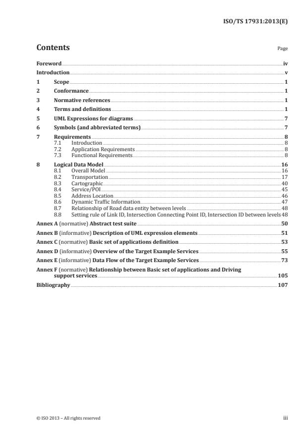
Contents Page
Foreword .iv
Introduction .v
1 Scope . 1
2 Conformance . 1
3 Normative references . 1
4 Terms and definitions . 1
5 UML Expressions for diagrams . 7
6 Symbols (and abbreviated terms) . 7
7 Requirements . 8
7.1 Introduction . 8
7.2 Application Requirements . 8
7.3 Functional Requirements . 8
8 Logical Data Model .16
8.1 Overall Model .16
8.2 Transportation .17
8.3 Cartographic .40
8.4 Service/POI .45
8.5 Address Location .46
8.6 Dynamic Traffic Information.47
8.7 Relationship of Road data entity between levels .48
8.8 Setting rule of Link ID, Intersection Connecting Point ID, Intersection ID between levels 48
Annex A (normative) Abstract test suite .50
Annex B (informative) Description of UML expression elements .51
Annex C (normative) Basic set of applications definition .53
Annex D (informative) Overview of the Target Example Services .55
Annex E (informative) Data Flow of the Target Example Services .73
Annex F (normative) Relationship between Basic set of applications and Driving
support services .105
Bibliography .107
Foreword
ISO (the International Organization for Standardization) is a worldwide federation of national standards
bodies (ISO member bodies). The work of preparing International Standards is normally carried out
through ISO technical committees. Each member body interested in a subject for which a technical
committee has been established has the right to be represented on that committee. International
organizations, governmental and non-governmental, in liaison with ISO, also take part in the work.
ISO collaborates closely with the International Electrotechnical Commission (IEC) on all matters of
electrotechnical standardization.
International Standards are drafted in accordance with the rules given in the ISO/IEC Directives, Part 2.
The main task of technical committees is to prepare International Standards. Draft International
Standards adopted by the technical committees are circulated to the member bodies for voting.
Publication as an International Standard requires approval by at least 75 % of the member bodies
casting a vote.
In other circumstances, particularly when there is an urgent market requirement for such documents, a
technical committee may decide to publish other types of normative document:
— an ISO Publicly Available Specification (ISO/PAS) represents an agreement between technical
experts in an ISO working group and is accepted for publication if it is approved by more than 50 %
of the members of the parent committee casting a vote;
— an ISO Technical Specification (ISO/TS) represents an agreement between the members of a
technical committee and is accepted for publication if it is approved by 2/3 of the members of the
committee casting a vote.
An ISO/PAS or ISO/TS is reviewed after three years in order to decide whether it will be confirmed for
a further three years, revised to become an International Standard, or withdrawn. If the ISO/PAS or
ISO/TS is confirmed, it is reviewed again after a further three years, at which time it must either be
transformed into an International Standard or be withdrawn.
ISO/TS 17931 was prepared by Technical Committee ISO/TC 204, Intelligent transport systems.
This corrected version of ISO/TS 17931 contains higher quality figures in Annex D, which improve legibility.
iv © ISO 2013 – All rights reserved
Introduction
The purpose of this proposal is to extend the existing specifications for map databases in order to
provide greater support for applications and/or application developments of Cooperative ITS that may
use Local Dynamic Map.
The functional requirements and data model for in-vehicle navigation are already defined in
ISO/TS 20452. However, the map-related functional requirements, data model, and data elements
needed for Local Dynamic Map for Cooperative ITS have not yet been defined.
This proposal can help developers of applications for Cooperative ITS by broadening its applicability.
Such applications will benefit by the availability of a standardized data model and data elements. The
resulting work will shorten developers’ time-to-market for new products and services.
1)
The scope of this proposal is within the scope of ISO 14296 which was approved in April, 2011. However,
in order to meet the schedule requirement of Mandate M/453 issued by European Commission, the scope
of this proposal is limited to publishing a Technical Specification for the Local Dynamic Map component
of ISO 14296.
1) Under preparation.
TECHNICAL SPECIFICATION ISO/TS 17931:2013(E)
Intelligent transport systems — Extension of map database
specifications for Local Dynamic Map for applications of
Cooperative ITS
1 Scope
This Technical Specification provides the map-related functional requirements, data model (logical data
model/logical data organization), and data elements for Local Dynamic Map for those applications of
Cooperative ITS that require information derived from map databases.
It is focused on data elements of a static nature.
2 Conformance
Data structures shall be provided as specified in Clauses 8.
Any data structure claiming conformance with this Technical Specification shall pass the requirements
presented in the abstract test suite in Annex A.
UML Expressions for diagrams in this Technical Specification shall be compliant with ISO/IEC 19501:2005.
3 Normative references
The following referenced documents are indispensable for the application of this document. For dated
references, only the edition cited applies. For undated references, the latest edition of the referenced
document (including any amendments) applies.
ISO 14825:2011, Intelligent transport systems — Geographic Data Files (GDF) — GDF5.0
ISO/TS 20452:2007, Requirements and Logical Data Model for a Physical Storage Format (PSF) and an
Application Program Interface (API) and Logical Data Organization for PSF used in Intelligent Transport
Systems (ITS) Database Technology
ETSI TC ITS TR 102638, Basic set of applications definitions
ETSI TC ITS TR 102863, Intelligent Transport Systems (ITS); Vehicular Communications; Basic set of
applications; Local Dynamic Map (LDM); Rationale for and guidance on standardization
4 Terms and definitions
For the purposes of this document, the following terms and definitions apply.
4.1
Address Location
application category that deals with the task of expressing a real-world position in terms of the PSF data
representation
Note 1 to entry: Address Location is one of the six application categories.
4.2
Advisory Point
data model entity that provides information about an approaching condition on a road that may require
some action by the driver of a vehicle
4.3
Application category
basic sub-function within the set of functionality for vehicle navigation and traveler information
system applications
Note 1 to entry: This Technical Specification identifies six application categories: Positioning, Route Planning,
Route Guidance, Map Display, Address Location, Services and POI Information Access.
4.4
Background
data model package that is composed of Background Imagery, Map Data Background, Cartographic
Feature Type, Figure Element and Picture file entity for displaying Map
4.5
Background Imagery
data model entity that provides background images upon which the road network of an area may be displayed
4.6
Building & Facility
data model entity that provides the location and shape of road side features such as a toll gate, or a fixed
Road Side ITS station
4.7
Cartographic
data model package represents geometric information for display purposes, having non-explicit topology
and 0-, 1- and 2-dimensional types and images
4.8
Cartographic Feature Type
data model entity that provides cartographic feature by their type (Symbol, Point, Polyline and Polygon)
4.9
Caution Point
data model entity that provides warning information about an approaching potential hazard on the
Road Elements that may require some action by the driver of a vehicle
4.10
Detailed Special Route
data model entity that provides the detailed information of Special Route such as the ordered sequence
of Link and Intersection lists, length of route and fee of toll road
4.11
Direction Guide
data model entity that provides the guidance information for a path which is composed of the entrance
Link and the exit Link connected to an Intersection
4.12
Display point
0-dimensional type of cartographic feature
4.13
District Name
data model entity that provides the name of a geographic area feature for each Link connected to
an intersection
4.14
Figure Element
data model entity that provides the shape data of a cartographic feature for displaying a map
2 © ISO 2013 – All rights reserved
4.15
Geo cording
determination of a link or node based on address information describing and/or naming a location
4.16
Graphic Text
data model entity that stores name text that is associated with all or part of a cartographic feature
Note 1 to entry: It is language-dependent and can contain a suggested display location, orientation, language
code, priority (or importance), suggested scale range, and bounding box.
4.17
Intersection
GDF level 2 representation of a crossing which bounds a road or a ferry as a complex feature composed
of one or more GDF level 1 junctions, Road Elements and enclosed traffic areas
4.18
Intersection Connecting Point
data model entity for a topological junction of two or more links or end bounding a link
Note 1 to entry: A link stores the coordinate value of the corresponding GDF junction.
4.19
Intersection Cost
data model entity that provides the time or monetary cost between the entrance Link and exit Link of
Intersection for calculating route
4.20
Intersection Link
data model entity that provides the Links in the Intersection used for determining the path through
an intersection
4.21
Intersection Link Shape
data model entity that provides the shape of the Intersection Link for displaying a path
4.22
Intersection Name
data model entity that provides the name of an Intersection. An Intersection may have one or more
names corresponding to the direction of entering into the intersection
4.23
Junction
it represents a navigable feature which is either a named GDF junction or named GDF intersection, and
that relates a named navigable feature to a set of links and nodes and a place
4.24
Landmark
point, line or area feature that can be used to clarify the directions generated to describe a route
Note 1 to entry: It can be associated to a node or a link.
Note 2 to entry: A Landmark cannot be in the Services, Administrative Areas, or Public Transportation Feature
themes of the GDF; however a facility in which a service is located can be a landmark.
4.25
Lane
data model entity that provides the lane information such as lane direction or lane width of Road Element
4.26
Lane Shape
data model entity that provides the shape geometry of the lane
4.27
Layer
sub-set of map data resulting from a subdivision of data of the same coverage area based on contents
(similar to ISO-GDF layer) and which is typically related to one or only a few of the application categories
EXAMPLE Route guidance data can be considered as one layer.
4.28
Level
sub-set of map data resulting from classification of data of the same semantically contents based on the
level of details/density, related to the concept of different map scales
Note 1 to entry: Level 0 is considered the lowest level (greatest detail); higher levels are numbered level 1, level 2, etc.
EXAMPLE Map display data can be organized into 6 levels representing different zoom scales.
4.29
Link
directed topological connection between two nodes, composed of an ordered sequence of one or more
segments and represented by an ordered sequence of zero or more shape points
4.30
Link Cost
data model entity that provides the time or monetary cost of the Link for calculating route
4.31
Local Dynamic Map
a conceptual data store which is embedded in an ITS station and which contains topographical, positional
and status information
4.32
Location Image
data model entity that provides a background image of the Road Element and the intersection upon
which guidance information is displayed
4.33
Map Data Background
data model entity that provides map database features for background display
4.34
Map Display
application category that deals with graphical information presentation
Note 1 to entry: Map Display is one of the six application categories.
4.35
Multilink
ordered aggregation of links which are at the same level, connected in sequence, share the same
functional classification, form of way, direction of travel, and perhaps additional PSF-builder-specified
characteristics, such that each link is contained in exactly one multilink
4.36
Parcel
database partitioning unit, corresponding to a certain coverage area and associated with one level and
containing data of one or more layers
Note 1 to entry: A parcel contains (at least) all nodes with positions enclosed by or located on the outline of its
coverage area plus (parts of) all links attached to these nodes.
Note 2 to entry: It can be partitioned such that the amount of data of one parcel is nearly the same as that of another.
4 © ISO 2013 – All rights reserved
4.37
Picture File
this entity is the file of picture object
4.38
Place
named area which can be used as part of address location
4.39
Place Reference Point
data model entity that provides a representative point within a Place
4.40
Point of Interest
destination and/or site of interest to travelers, usually non-commercial by nature
4.41
Polygon
2-dimensional type of cartographic feature
4.42
Polyline
1-dimensional type of cartographic feature
4.43
Positioning
application category that deals with the determination of vehicle location and map-matching
Note 1 to entry: Positioning is one of the six application categories.
4.44
Rectangle
unit of geographic space, defined by two parallels of min/max latitude and by two meridians of min/max
longitude, that represents the coverage area of the map data enclosed by or located on the outline of
the rectangle
4.45
Regular parcel
parcel shaped like a rectangle
Note 1 to entry: Regular parcels on the same generalization level are not intended to overlap.
4.46
Reverse geo cording
determination of the address description of a link or node (i.e. determination of an upwards path across
the place tree)
4.47
Road
GDF level 2 feature composed of one, many or no Road Elements and joining two intersections, serving
as the smallest independent unit of a road network at GDF level 2
4.48
Road Bridge and Tunnel
data model entity that provides information such as the length, height and slope of bridges and tunnels
4.49
Road Element
data model entity that is a primitive road feature. Road Element is the same as the Link except for
connecting to the Intersection
Note 1 to entry: Road Element is the same as Link.
4.50
Road Element Shape
data model entity that provides the shape geometry of the Road Element for displaying Road and Positioning
4.51
Route Guidance
application category that deals with the generation of graphical, textual, and/or audio instructions for
following a planned route
4.52
Road Marking
data model entity that provides the shape of painted markings on roads such as lane markings these
may be used for display purposes
4.53
Road Section
data model entity that is represented by an ordered sequence of one or more Road Element
4.54
Road Signage
data model entity that provides the detailed text of the road signage on the Road Element
Note 1 to entry: Route Guidance is one of the six application categories elements and joining two intersections,
serving as the smallest independent unit of a road network at GDF level 2.
4.55
Route Planning
application category that deals with the determination of routes between specified points
Note 1 to entry: Route Planning is one of the six application categories.
4.56
Segment
straight section of a link connecting either two successive shape points, or a shape point and a node, or
two nodes in case the link does not contain shape points
4.57
Service
data model entity for a commercial activity of interest to travelers as a destination and/or orientation
that is associated with Road Element(s), by which it can be accessed, and place(s)
Note 1 to entry: Service is further described by attributes including (at least) name and type; it can be associated
with other services by parent/child relationships (many to many).
Note 2 to entry: Service is used synonymously with POI within the logical data model.
4.58
Service and POI Information Access
application category that deals with the provision of POI information to the navigation application
Note 1 to entry: Services and POI Information Access is one of the six application categories.
4.59
Service and POI Reference Point
data model entity that provides a representative point of a Service and POI
4.60
Shape point
position along a link used to more accurately represent its geometric course, bounded by exactly two
segments
6 © ISO 2013 – All rights reserved
4.61
Special Route
data model entity that provides the pre-determined route such as scenic route or highway route
4.62
Street Address
data model entity that provides the geocoded Street Address of the Road Element
4.63
Symbol
it represents an icon associated with a cartographic feature
4.64
Topological Road Network
data model package that is composed of Road Element, Intersection, Link Cost, Intersection Cost, Traffic
Restriction, Special Route and Detailed Special Route
4.65
Traffic Location
data model entity that contains an external reference (e.g. VICS or RDS-TMC) and is linked to either place
or Road entities
4.66
Traffic Restriction
data model entity that provides the traffic restrictions such as one way or turn restrictions for route
calculation purposes
4.67
Transportation element
any feature from the Roads and Ferries feature theme of the GDF
5 UML Expressions for diagrams
This Technical Specification uses UML to express specific circumstances; the graphical elements are
used to express specific constraints and structural relationships. A full definition can be found in
ISO/IEC 19501:2005. However, a short introduction of elements is given in Annex B.
6 Symbols (and abbreviated terms)
ADAS Advanced Driver Assistance System
BSA Basic set of applications
DB Database
GDF Geographic Data File
ITS Intelligent Transport System
LDM Local Dynamic Map
LDO Logical Data Organization
POI Point of Interest
PSF Physical Storage Format
7 Requirements
7.1 Introduction
This Technical Specification defines application requirements and functional requirements.
7.2 Application Requirements
This Technical Specification supports Basic set of applications of Cooperative systems, Driving support
services, and navigation services.
Basic set of applications of Cooperative systems are defined in Annex C. Driving support services are
defined in Annex D. Relationship between Basic set of applications of Cooperative systems and Driving
support services are defined in Annex F.
7.3 Functional Requirements
7.3.1 Overview
Six functions (Map Display, Positioning, Route Planning, Route Guidance, Service/POI Information Access
and Address Location) are the same as ISO/TS 20452:2007. The other functions are newly defined by
this technical specification.
7.3.2 Map Display
7.3.2.1 General Description
The Map Display function is used to display a map of a specified geographic area. An application may
display maps to the end-user. The application may also accept end-user input that references the map
display (such as from a point and click device).
7.3.2.2 Functional Description
An application may display Points Features, Lines Features, Areas Features, Cartographic Text and Symbols
for a specified geographic area. This may include roads, physical features, administrative boundaries, and
names for all of these. Text and symbols can be positioned on a display to annotate this map.
The Map Display function provides cartographic data that can be used to display a map of any application
specified arbitrarily-oriented rectangle in the database. The data consist of the following database entities
to support a variety of map drawing styles: Cartographic Features, Cartographic Text and Symbols.
The application may allow the map to be zoomed in or out. The application may display different levels
of detail on a map display based on the zoom level. The application may allow the map to be rotated and
scrolled. When scrolling, if detailed data are not available, the application may automatically zoom the
map out to a level where data are available. The application may allow the end-user to access additional
information by selecting objects on the display. The application may display multiple windows.
Generating map images and managing displays are beyond the scope of this function.
To facilitate data access speed, this application groups cartographic data into levels. The higher levels contain
only the more significant cartographic features. The set of cartographic data is also selectable by level.
7.3.2.3 Requirements for Data model
Map Display provides the following methods of accessing data:
— R-1. via the Cartographic Features, Cartographic Text and Symbols for an application-specified
rectangle, level and Feature type;
8 © ISO 2013 – All rights reserved
— R-2. via the coordinates for application-specified Cartographic Features;
— R-3. via attributes for Cartographic Features, such as: feature type, name, and functional
classification;
— R-4. via the complete or partial Cartographic Features associated with application-specified
Transportation Elements;
— R-5. via the area (size) of an application-specified Area Feature;
— R-6. via the ability to retrieve additional information for Point, Line and Area Features which are
associated with Cartographic Features which may have been selected from the displayed map;
— R-7. via the Cartographic Text associated with a Cartographic Feature;
— R-8. via the Symbol associated with a Cartographic Feature;
— R-9. via returning the Cartographic Features and Cartographic Text in “draw-order”. For example, if
water is drawn before bridges, water features should be returned before bridge features.
— R-10. When no map data are available for an area requested by a function, the function may
distinguish between the case of “off the map” and the case of “no data at this location at this level”.
— R-11. The API shall allow a pre-fetch area of interest to be specified by a rectangle and application
specified level for retrieving Map Display data.
— R-12. display a map at the current location of the navigation system;
— R-13. display a marker on the map indicating the navigation system’s current location;
— R-14. scroll the displayed map as the navigation system moves, maintaining the position of the
marker indicating the navigation system’s current location;
— R-15. display a map at any location selected by the end-user. The end-user may specify the location
as an address, an intersection, a service, or by cursor position on the display;
— R-16. provide latitude and longitude, street address, and other information for a point indicated by
the cursor on the display;
— R-17. highlight a route on the display;
— R-18. highlight the point on a displayed map of a particular routing maneuver.
— R-19. Several levels of data are required for cartographic data, corresponding to different map scale
ranges. At the higher levels, the drawing detail for line features and area features is generalized.
— R-20. Access is required for data from all GDF Feature Themes, as well as attributes and conditions.
— R-21. Map display data shall be organized into Parcels.
— R-22. In order to allow easy identification of Parcels, Parcels shall be rectangular.
— R-23. Links crossing Parcel boundaries shall be cut at the Parcel boundary.
— R-24. In order to minimize the number of Parcels accessed, any link crossing into a parcel, with or
without a node or intermediate point in that Parcel, shall be represented in that parcel.
7.3.3 Positioning
7.3.3.1 General Description
The Positioning function is used to determine vehicle location, for example latitude and longitude of a road
network entity and for Map Matching. Map Matching is the method of determining where the navigation
system has moved in the road network based on the navigation system’s previous location and data about
the navigation system’s motion from external inputs. It corrects the geo-localization on the routes.
7.3.3.2 Functional Description
“Positioning” seeks a position and orientation of a navigation system relative to the transportation
network with respect to the map data representing the real world. An application may dynamically
determine the navigation system’s current position while the navigation system is in motion. Map
Matching can continue “in the background” even while other functions are being performed so the
navigation system always “knows where it is”, with an accuracy depending on the map-matching. Map
Matching algorithms are beyond the scope of this Technical Specification.
7.3.3.3 Requirements for Data model
For the purpose of positioning, the following functions shall be provided:
— R-25. a single set of coordinates for an application-specified Point Feature in the Roads and Ferries theme;
— R-26. the set of Edges, Nodes and/or Intermediate Points for an application-specified Feature or set of
connected Features in the Roads and Ferries theme;
— R-27. the set of topologically connected Features in the Roads and Ferries Theme connected to an
application specified Feature in the Roads and Ferries theme;
— R-28. a single set of coordinates for an application-specified Line Feature in the Roads and Ferries
theme and application-specified percentage of the distance along the Feature;
— R-29. the set of Features, Edges, Nodes and/or Intermediate Points in the Roads and Ferries theme
within an application-specified rectangle;
— R-30. positioning related Attributes, Conditions and Relationships (i.e. Prohibited Manoeuvres,
Direction of Traffic Flow) for an application-specified Feature in the Roads and Ferries theme;
— R-31. the entry and exit angles for the set of Transportation Elements connected to an application-
specified Intersection or Junction;
— R-32. The specification shall support a single, world-wide, latitude/longitude-based coordinate
reference system. The International Terrestrial Reference Frame (ITRF) is chosen because it is
maintained by an international body. It is considered equivalent to WGS84 because the two systems
currently have less than 1 m difference;
— R-33. only one coordinate system can be used in a single piece of storage media;
— R-34. when an application tracks progress along the route and provides maneuver instructions at
appropriate points to the end-user;
— R-35. when an application determines whether the navigation system has left the planned route;
— R-36. when an application calculates a route to the requested destination from the navigation
system’s current position;
— R-37. when an application scrolls the displayed map;
— R-38. when an application selects services by geographic proximity;
— R-39. when an application is displaying the navigation system’s position on a map;
— R-40. when an application displays a map around a location relative to the navigation system’s
current position;
— R-41. Positioning may receive planned route information from the Route Planning application for
use in Map Matching.
10 © ISO 2013 – All rights reserved
— R-42. Only access to the lowest level of data is required.
— R-43. Only access to the data represented in the Roads and Ferries theme is required.
— R-44. Positioning data shall be organized into parcels.
— R-45. In order to minimize the number of parcels accessed, any link crossing into a parcel, with or
without a node or intermediate point in that parcel, shall be represented in that parcel.
— R-46. In order to allow fast spatial access to parcels, parcels shall be accessed by their bounding
rectangles. The shapes of parcels on the lowest level shall not overlap.
7.3.4 Route Planning
7.3.4.1 General Description
The Route Planning function is used to determine routes from one user-specified location to another.
7.3.4.2 Functional Description
Navigation applications may calculate routes based on attributes of the transportation network. Applications
may allow end-users to specify criteria for the route such as “shortest distance”, “no highways”, etc. As
a basic operation, a user indicates a departure position, which could be the navigation system’s current
position, and selects a destination (place to go) and possibly one or more waypoints. A suitable route is
then calculated. Routing is not limited to automobile transportation only. This function supports routing
via any mode represented in the database. This may include rail and water ferries, taxis, and routes only
accessible by bicycle or foot. Other forms of public transportation may be considered in the future.
The route calculation algorithms are outside the scope of this functional description.
To improve data access speed, the Logical Data Organization groups transportation features into levels.
The higher levels contain only the more significant features (e.g. highways and main roads). These may
be aggregated. Correspondences between features at different levels shall be made available to the
application. The functions specified in the requirements below allow selection by level.
7.3.4.3 Requirements for Data model
The Route Planning application provides the following methods of accessing data that can be used for routing:
— R-47. via the set of topologically connected Links for an application-specified Link at an application-
specified level;
— R-48. via routing-related Attributes for an application-specified Transportation Element or set of
connected Transportation Elements, such as: Node Coordinates (of the bounding Nodes of a Link),
Measured Length, Functional Road Class, Number Of Lanes, Average Speed, Divided Road Element,
Form Of Way, as well as access characteristics, Conditions, and other Relationships;
— R-49. via navigation attributes for Roads and Intersections;
— R-50. via corresponding Link for an application-specified Link at an application-specified different level;
— R-51. via a set of topologically connected GDF Roads for an application specified GDF Road at an
application specified level at certain levels to be determined;
— R-52. via a set of GDF Road Elements and GDF Junctions, which comprise a GDF Road or GDF
Intersection;
— R-53. via the GDF Road or GDF Intersection for an application-specified GDF Road Element or
GDF Junction;
— R-54. via the corresponding entity representing a GDF Junction or Intersection for an application-
specified entity representing a GDF Junction or Intersection at an application-specified different level;
— R-55. via effective time or date periods for turn, travel, or other Conditions;
— R-56. via location references which are stored in the database for an application-specified set of
Transportation Elements;
— R-57. via a set of Transportation Elements for an application-specified location reference, which is
stored in the database;
— R-58. via the entry and exit angles for the set of Links connected to an application-specified
Intersection or Junction;
— R-59. via historic and forecast traffic conditions, incidents, and events information for a specified
Transportation Element or set of Transportation Elements;
— R-60. via a DAL capable of providing transparent access to static and dynamic traffic information. It
shall not preclude or require the integration of dynamic traffic information from external systems;
— R-61. via an API allowing a pre-fetch area of interest specified by feature ID or rectangle for
retrieving Route Planning data at an application-specified level.
— R-62. The Route Planning application accepts other information from the Positioning application
when calculating a route to the requested destination from the navigation system’s current position.
— R-63. The Route Planning application provides information about the planned route to the Positioning
application when determining whether the navigation system has left the planned route.
— R-64. The Route Planning application provides information about the planned route to the Route
Guidance application for generating driving instructions.
— R-65. The Route Planning application provides information about the planned route to the Services
and POI Information Access application for geographic selection of services with proximity to the
planned route.
— R-66. The Route Planning application accepts input from the Services and POI Information Access
and Address Location application when determining end-points or way-points for a route.
— R-67. The Route Planning application provides information about the planned route to the Map
Display Application when indicating the course of the planned route on the graphical map display.
— R-68. Only access to the data represented in the Roads and Ferries theme is required. Enclosed traffic
areas shall be represented by links and nodes.
— R-69. The shape of a parcel on a given level shall be contained in the shape of exactly one parcel at a
higher level. The shapes of parcels on the same level shall not overlap.
— R-70. For route planning data, references to parcels on the same level and on the level(s) above and
below are required.
— R-71. In order to have optimally filled parcels, parcels may have different coverage sizes.
— R-72. For route planning data, no intermediate points are required for the representation of links. A
representation of turn angles, link length and the link cost are required.
— R-73. There is no requirement to create an additional node where a link crosses a parcel boundary.
— R-74. For route planning data, links crossing a parcel boundary should be stored as a whole in those
parcels where they are connected to other links in the same parcel.
— R-75. In order to have fast access to parcels, parcels shall be accessed by their bounding rectangles.
12 © ISO 2013 – All rights reserved
— R-76. A separate computation is required to find nodes or links in the network data corresponding
to origin, intermediate and destination points. The manner in which the nodes or links are found is
outside the scope of this Technical Specification.
7.3.5 Route Guidance
7.3.5.1 General Description
The Route Guidance function is used to generate instructions for following a route.
7.3.5.2 Functional Description
The Route Guidance function generates step-by-step instructions for following a route. These
instructions may include compass heading, distance, road names, sign text, landmarks, and still or
motion images. These instructions may also include maneuver details such as turn angle, merges, and
road name changes. Route Guidance may be given using text, voice or graphics.
7.3.5.3 Requirements for Data model
Route Guidance provides the following methods of accessing data used for guidance of a route:
— R-77. via guidance-relevant features and relationships related to an application-specified
Transportation Element, or set of Transportation Elements, such as: intersecting Road Elements,
Signpost Information, Conditions and Landmarks along the Transportation Element;
— R-78. via guidance attributes for an application-specified Transportation Element, or set of
Transportation Elements, such as: Road Names, Length, Direction Of Traffic Flow, and Form Of Way;
— R-79. via indicating whether an application-specified Junction is a part or all of an Intersection;
— R-80. via indicating whether an application-specified link is a regular link, a super link or part of
a super link;
— R-81. via connected Transportation Elements for an application-specified Junction;
— R-82. via connected Transportation Elements for an application-specified Intersection which are
not part of that Intersection, such as the set of Road Elements connected to a Roundabout;
— R-83. via component Transportation Elements of an application-specified Intersection, such as the
set of Road Elements and Junctions which make up a roundabout;
— R-84. via data about the transition from an application-specified Link to an application-specified
series of connected Links, such as: the existence of a tollbooth or gate;
— R-85. via node and Intermediate Point positions for Line Features to support displaying maneuver
“arrows” for route guidance;
— R-86. via cartographic data for the Line Features comprising an intersection for the derivation of
intersection schematics;
— R-87. via entry and exit angles for the set of Transportation Elements connected to an application-
specified Intersection or Junction;
— R-88. via phonetic strings in an application-specified language for pronunciation of any named
entity in the database;
— R-89. via phonetic strings in an application-specified language for commonly used guidance words;
— R-90. via digitized pronunciation data in an application-specified language for commonly used
guidance words;
— R-91. via API allowing a prefect area of interest specified by a rectangle for retrieving Route
Guidance data;
— R-92. via image data for optional picture guidance.
— R-93. provide guidance while the navigation system is in motion, based on a calculated route and
map matching;
— R-94. track progress along the route and provid
...
Questions, Comments and Discussion
Ask us and Technical Secretary will try to provide an answer. You can facilitate discussion about the standard in here.
Loading comments...