

ISO/FDIS 10121-2
(Main)Test methods for assessing the performance of gas-phase air cleaning media and devices for general ventilation — Part 2: Gas-phase air cleaning devices (GPACD)
- Abstract
ISO 10121-2:2013 aims to provide an objective test method to estimate the performance of any full size gas filtration device (GPACD) for general filtration regardless of media or technique used in the device. In fact, the goal of this part of ISO 10121 is to avoid relating the test data to internal parameters altogether. The benefit with this approach is that customers of GPACDs will be able to concentrate on price/performance and suppliers will have access to a normative and objective test standard that will not require the release of proprietary information or reverse engineering of the product. To ensure objectivity for test equipment suppliers, no specific design of the test apparatus is specified. Instead requirements of apparatus properties and validation tests are specified. However, different design examples in present use are outlined. ISO 10121-2:2013 can also be used with technologies such as scrubbers, absorbers, non-sorptive devices or packed columns as long as they fit into the test apparatus, can be meaningfully judged by the test method and are intended for general ventilation applications, both residential and non residential. Nuclear and military applications are specifically excluded.
- Status
- Not Published
- Technical Committee
- ISO/TC 142 - Cleaning equipment for air and other gases
- Drafting Committee
- ISO/TC 142/WG 8 - Gas-phase air cleaning devices
- Current Stage
- 5020 - FDIS ballot initiated: 2 months. Proof sent to secretariat
- Start Date
- 22-Sep-2026
- Completion Date
- 22-Sep-2026
Buy Documents
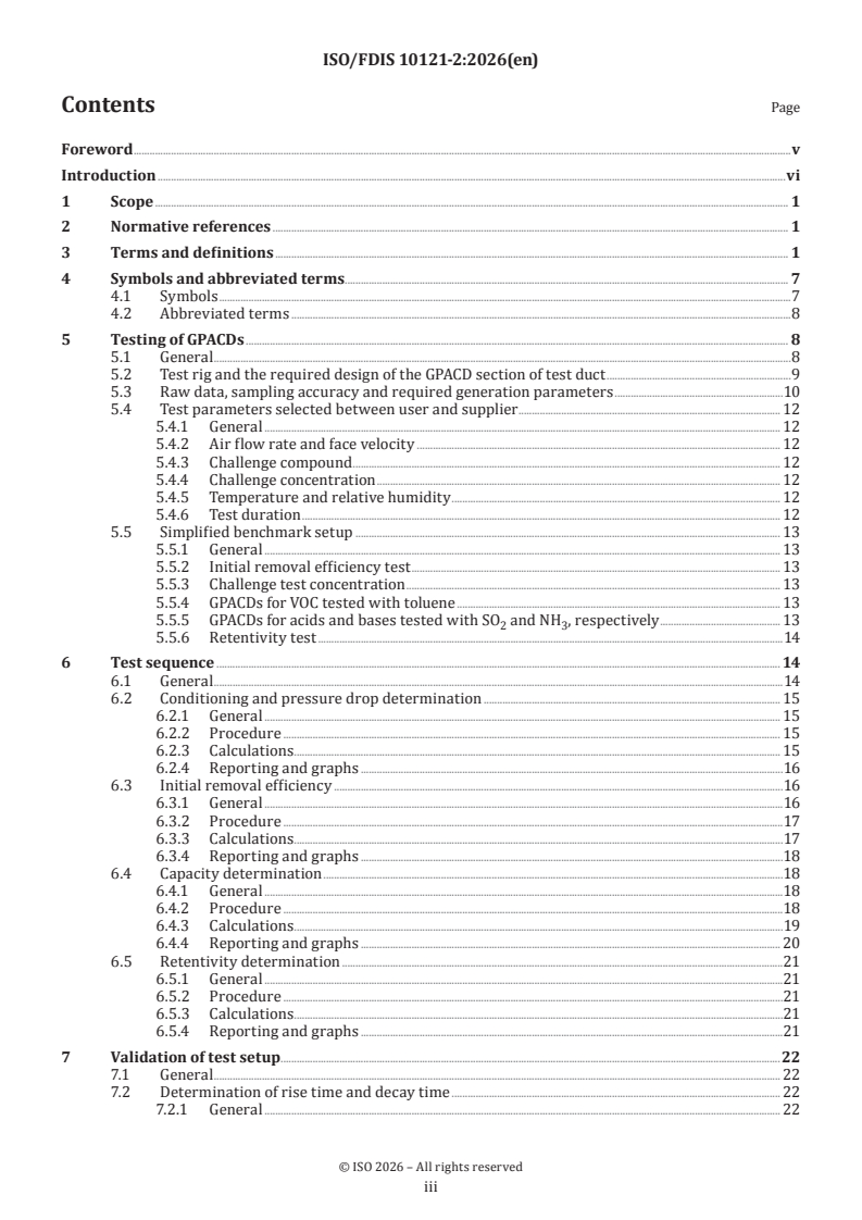
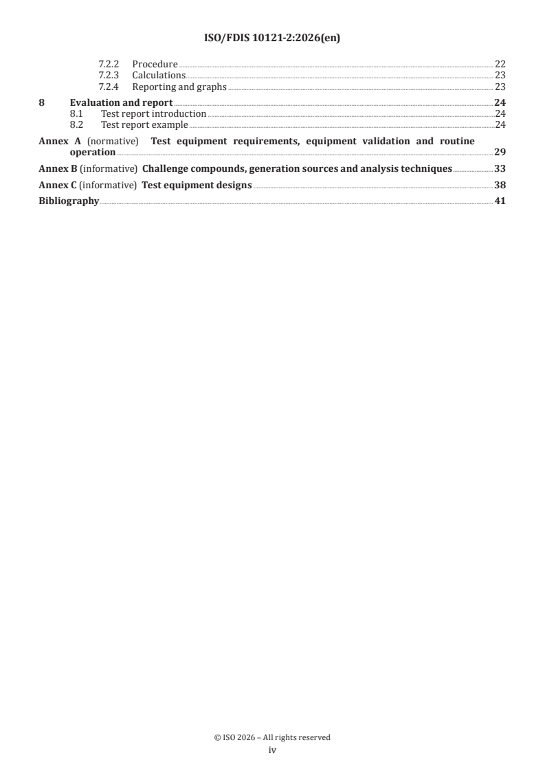
ISO/FDIS 10121-2 - Test methods for assessing the performance of gas-phase air cleaning media and devices for general ventilation — Part 2: Gas-phase air cleaning devices (GPACD)
REDLINE ISO/FDIS 10121-2 - Test methods for assessing the performance of gas-phase air cleaning media and devices for general ventilation — Part 2: Gas-phase air cleaning devices (GPACD)
ISO/FDIS 10121-2 is an ISO document that specifies an objective test method for gas-phase air cleaning devices (GPACD) used in general ventilation. It is written for people who need to compare device performance in practice - suppliers, test laboratories, quality teams and buyers - and it focuses on pressure drop, removal efficiency, capacity and retentivity without requiring disclosure of proprietary internal design details.
What does ISO/FDIS 10121-2 specify?
ISO/FDIS 10121-2 specifies how to test full, half or quarter size GPACD for general filtration, regardless of the media or technique used inside the device. It also states what the test rig must achieve, how the test sequence is run, how results are validated and how the report is prepared.
The document applies to GPACD intended for residential and non-residential general ventilation applications, including technologies such as scrubbers, absorbers, non-sorptive devices and packed columns when they fit the apparatus and can be judged by the method. Nuclear and military applications are excluded.
| Annex | What it covers |
|---|---|
| Annex A | Normative requirements for test equipment, validation and routine operation |
| Annex B | Informative challenge compounds, generation sources and analysis techniques |
| Annex C | Informative example test equipment designs |
The document is organized into clauses on scope, references, terms, symbols, testing, the test sequence, validation, and evaluation and report. In practice, that means the standard tells the user both what to measure and how to prove that the test setup is trustworthy.
What are the key requirements of ISO/FDIS 10121-2?
ISO/FDIS 10121-2 requires a performance-based test setup, not a prescribed machine design. The practical result is that different laboratories can use different rigs, but they must demonstrate the same measurement quality and validation performance.
1. The test rig must control the air stream properly
Clause 5 requires the GPACD to be installed without leakage or bypass, with the test air stream uniformly mixed and with equal velocity and concentration across the cross-section. The duct section, sampling points and flow measurement point are defined so that readings represent the whole device, not just one local spot.
This matters because a poorly mixed stream or a leak can make a good device look bad, or the reverse.
2. The device size and duct geometry are constrained
Clause 5 requires the GPACD section of the test duct to have fixed internal dimensions for the standardized test arrangement, and it allows adaptor plates for smaller devices. The document also states that actual size and configuration should be tested.
This matters because face area and duct geometry affect face velocity, residence time and pressure drop, so the reported results must match the device configuration being sold or evaluated.
3. Measurements must be recorded continuously and with defined accuracy
Clause 5 and Annex A require continuous logging of concentrations, pressure, temperature, relative humidity and air flow rate, with defined accuracy and sampling frequency. Annex A also sets requirements for sensor calibration, detector response, leak testing, background contamination and challenge compound distribution.
This matters because the method depends on time-resolved data, especially for breakthrough, rise time, decay time and capacity calculations.
4. The test sequence is staged
Clause 6 sets the sequence as conditioning and pressure drop determination, initial removal efficiency, capacity determination and retentivity determination. At least the capacity part is expected to be performed, and any part that is run must comply with the standard.
This matters because the device must first be stabilized under clean air before performance data are taken, and because later parts of the test build on earlier ones.
5. Initial removal efficiency is measured at low challenge concentration
Clause 6.3 measures initial removal efficiency at a low challenge concentration, using either an application-specific compound or the simplified benchmark setup. The result shows how the GPACD performs before meaningful loading begins.
This matters for buyers because it shows early-life performance at conditions close to the intended use, not just at severe laboratory exposure.
6. Capacity is measured at higher challenge concentration
Clause 6.4 uses a higher challenge concentration to determine capacity and the removal efficiency-versus-time and removal efficiency-versus-capacity behavior. The document also explains that one analyzer may require interpolation between upstream and downstream measurements.
This matters because capacity shows how long the GPACD can continue to work before performance falls to a chosen end point.
7. Retentivity checks desorption after challenge stops
Clause 6.5 measures retentivity directly after the capacity test by switching off the challenge compound and observing the downstream concentration decay. This identifies how much sorbed contaminant the device gives back to the air stream.
This matters for applications where stored contaminant could later re-enter the ventilation system.
8. Validation and lag times are mandatory parts of the method
Clause 7 requires validation of the test setup before testing starts, including rise time and decay time determination for each challenge compound, concentration and air flow rate used. These lag times are then used to discard transition data correctly.
This matters because without lag-time correction, the reported concentration data can be distorted by tubing, walls and analyzer response.
What terms does ISO/FDIS 10121-2 define?
- Absorption - transport and dissolution of one substance into another so they form a solution-like mixture.
- Adsorption - attachment of gas or vapour molecules to the exposed surface of a solid.
- Breakthrough - the amount of gaseous contaminant leaving the GPACD in the effluent.
- Challenge concentration - the concentration of test contaminant in the air stream before filtration.
- Gas-phase air cleaning device (GPACD) - a fixed-size assembly that removes specific gas- or vapour-phase contaminants from air.
- Capacity - the amount of selected sorbate a GPACD can hold at the stated test conditions and end point.
- Retentivity - the ability of an adsorbent or GPACD to resist desorption after challenge breakthrough.
- Penetration - the ratio of downstream to upstream contaminant concentration.
Who uses ISO/FDIS 10121-2?
ISO/FDIS 10121-2 is used by GPACD suppliers, test laboratories, and customers who need comparable performance data for general ventilation products. It is also relevant to quality managers and buyers who have to specify, verify or compare pressure drop, efficiency, capacity and retentivity.
The standard is especially useful where the media and device design are proprietary, because it provides a neutral test interface without requiring the release of internal design details. It also helps test equipment builders and validation teams because Annex A and Annex C describe how a compliant setup can be built and checked.
What changed in ISO/FDIS 10121-2 from the previous edition?
ISO/FDIS 10121-2:2026 cancels and replaces ISO 10121-2:2013. The document states these main changes:
- terms and definitions were updated to conform with ISO 29464:2024;
- the toluene concentration was adjusted in the simplified benchmark test for initial efficiency;
- the other challenge concentrations now conform with ISO 10121-1 and ISO 10121-3;
- Annex B was reviewed and concentration recommendations were removed for compounds requiring special attention;
- several subclauses were reworded and clarified;
- the naming of challenge gas, challenge species and challenge compound was harmonized;
- formulae in 6.3.2 were corrected.
Which standards are used with ISO/FDIS 10121-2?
ISO/FDIS 10121-2 cites ISO 16890-2:2022 as a normative reference. That standard contributes the measurement of fractional efficiency and air flow resistance, and Annex A also points to its method for checking concentration homogeneity across the duct cross-section.
The introduction also identifies companion parts of the ISO 10121 series: ISO 10121-1 for gas-phase air cleaning media and ISO 10121-3 for classification of GPACD for outdoor air pollution applications. ISO 29464:2024 is used as the source for many of the terms and definitions.
What does the ISO/FDIS 10121-2 document contain?
Clause 5 explains the test rig, measurement positions, raw data requirements, test parameters and the simplified benchmark setup. Clause 6 gives the step-by-step procedures for conditioning, pressure drop, initial removal efficiency, capacity and retentivity, including formulas and example graphs.
Clause 7 covers validation of the setup and determination of rise and decay times. Clause 8 provides the reporting structure and an example test report, including what graphs and summary values to present.
Annex A contains tabulated requirements for sensor accuracy, validation checks and routine operation. Annex B lists challenge compounds, generation sources and preferred analysis techniques, while Annex C shows example test rig designs and how the ductwork can be arranged in practice.
Relations
- Effective Date
- 12-Feb-2026
- Effective Date
- 30-Sep-2023
Buy Documents
ISO/FDIS 10121-2 - Test methods for assessing the performance of gas-phase air cleaning media and devices for general ventilation — Part 2: Gas-phase air cleaning devices (GPACD)
REDLINE ISO/FDIS 10121-2 - Test methods for assessing the performance of gas-phase air cleaning media and devices for general ventilation — Part 2: Gas-phase air cleaning devices (GPACD)
Get Certified
Connect with accredited certification bodies for this standard

DIBt (Deutsches Institut für Bautechnik)
German Institute for Building Technology.
DIN CERTCO
DIN Group product certification.

Aboma Certification B.V.
Specialized in construction, metal, and transport sectors.
Sponsored listings
Frequently Asked Questions
ISO/FDIS 10121-2 is a draft published by the International Organization for Standardization (ISO). Its full title is "Test methods for assessing the performance of gas-phase air cleaning media and devices for general ventilation — Part 2: Gas-phase air cleaning devices (GPACD)". This standard covers: ISO 10121-2:2013 aims to provide an objective test method to estimate the performance of any full size gas filtration device (GPACD) for general filtration regardless of media or technique used in the device. In fact, the goal of this part of ISO 10121 is to avoid relating the test data to internal parameters altogether. The benefit with this approach is that customers of GPACDs will be able to concentrate on price/performance and suppliers will have access to a normative and objective test standard that will not require the release of proprietary information or reverse engineering of the product. To ensure objectivity for test equipment suppliers, no specific design of the test apparatus is specified. Instead requirements of apparatus properties and validation tests are specified. However, different design examples in present use are outlined. ISO 10121-2:2013 can also be used with technologies such as scrubbers, absorbers, non-sorptive devices or packed columns as long as they fit into the test apparatus, can be meaningfully judged by the test method and are intended for general ventilation applications, both residential and non residential. Nuclear and military applications are specifically excluded.
ISO 10121-2:2013 aims to provide an objective test method to estimate the performance of any full size gas filtration device (GPACD) for general filtration regardless of media or technique used in the device. In fact, the goal of this part of ISO 10121 is to avoid relating the test data to internal parameters altogether. The benefit with this approach is that customers of GPACDs will be able to concentrate on price/performance and suppliers will have access to a normative and objective test standard that will not require the release of proprietary information or reverse engineering of the product. To ensure objectivity for test equipment suppliers, no specific design of the test apparatus is specified. Instead requirements of apparatus properties and validation tests are specified. However, different design examples in present use are outlined. ISO 10121-2:2013 can also be used with technologies such as scrubbers, absorbers, non-sorptive devices or packed columns as long as they fit into the test apparatus, can be meaningfully judged by the test method and are intended for general ventilation applications, both residential and non residential. Nuclear and military applications are specifically excluded.
ISO/FDIS 10121-2 is classified under the following ICS (International Classification for Standards) categories: 91.140.30 - Ventilation and air-conditioning systems. The ICS classification helps identify the subject area and facilitates finding related standards.
ISO/FDIS 10121-2 has the following relationships with other standards: It is inter standard links to FprEN ISO 10121-2, ISO 10121-2:2013. Understanding these relationships helps ensure you are using the most current and applicable version of the standard.
ISO/FDIS 10121-2 is available in PDF format for immediate download after purchase. The document can be added to your cart and obtained through the secure checkout process. Digital delivery ensures instant access to the complete standard document.
Standards Content (Sample)
FINAL DRAFT
International
Standard
ISO/TC 142
Test methods for assessing the
Secretariat: UNI
performance of gas-phase air
Voting begins on:
cleaning media and devices for
2026-09-22
general ventilation —
Voting terminates on:
2026-11-17
Part 2:
Gas-phase air cleaning devices
(GPACD)
Méthodes d'essai pour l'évaluation de la performance des médias
et des dispositifs de filtration moléculaire pour la ventilation
générale —
Partie 2: Dispositifs de filtration moléculaire (GPACD)
RECIPIENTS OF THIS DRAFT ARE INVITED TO SUBMIT,
WITH THEIR COMMENTS, NOTIFICATION OF ANY
RELEVANT PATENT RIGHTS OF WHICH THEY ARE AWARE
AND TO PROVIDE SUPPOR TING DOCUMENTATION.
IN ADDITION TO THEIR EVALUATION AS
BEING ACCEPTABLE FOR INDUSTRIAL, TECHNO-
ISO/CEN PARALLEL PROCESSING LOGICAL, COMMERCIAL AND USER PURPOSES, DRAFT
INTERNATIONAL STANDARDS MAY ON OCCASION HAVE
TO BE CONSIDERED IN THE LIGHT OF THEIR POTENTIAL
TO BECOME STAN DARDS TO WHICH REFERENCE MAY BE
MADE IN NATIONAL REGULATIONS.
Reference number
FINAL DRAFT
International
Standard
ISO/TC 142
Test methods for assessing the
Secretariat: UNI
performance of gas-phase air
Voting begins on:
cleaning media and devices for
general ventilation —
Voting terminates on:
Part 2:
Gas-phase air cleaning devices
(GPACD)
Méthodes d'essai pour l'évaluation de la performance des médias
et des dispositifs de filtration moléculaire pour la ventilation
générale —
Partie 2: Dispositifs de filtration moléculaire (GPACD)
RECIPIENTS OF THIS DRAFT ARE INVITED TO SUBMIT,
WITH THEIR COMMENTS, NOTIFICATION OF ANY
RELEVANT PATENT RIGHTS OF WHICH THEY ARE AWARE
AND TO PROVIDE SUPPOR TING DOCUMENTATION.
© ISO 2026
IN ADDITION TO THEIR EVALUATION AS
All rights reserved. Unless otherwise specified, or required in the context of its implementation, no part of this publication may
BEING ACCEPTABLE FOR INDUSTRIAL, TECHNO-
ISO/CEN PARALLEL PROCESSING
LOGICAL, COMMERCIAL AND USER PURPOSES, DRAFT
be reproduced or utilized otherwise in any form or by any means, electronic or mechanical, including photocopying, or posting on
INTERNATIONAL STANDARDS MAY ON OCCASION HAVE
the internet or an intranet, without prior written permission. Permission can be requested from either ISO at the address below
TO BE CONSIDERED IN THE LIGHT OF THEIR POTENTIAL
or ISO’s member body in the country of the requester.
TO BECOME STAN DARDS TO WHICH REFERENCE MAY BE
MADE IN NATIONAL REGULATIONS.
ISO copyright office
CP 401 • Ch. de Blandonnet 8
CH-1214 Vernier, Geneva
Phone: +41 22 749 01 11
Email: copyright@iso.org
Website: www.iso.org
Published in Switzerland Reference number
ii
Contents Page
Foreword .v
Introduction .vi
1 Scope . 1
2 Normative references . 1
3 Terms and definitions . 1
4 Symbols and abbreviated terms. 7
4.1 Symbols .7
4.2 Abbreviated terms .8
5 Testing of GPACDs . 8
5.1 General .8
5.2 Test rig and the required design of the GPACD section of test duct .9
5.3 Raw data, sampling accuracy and required generation parameters .10
5.4 Test parameters selected between user and supplier . 12
5.4.1 General . 12
5.4.2 Air flow rate and face velocity . 12
5.4.3 Challenge compound . . 12
5.4.4 Challenge concentration . 12
5.4.5 Temperature and relative humidity . 12
5.4.6 Test duration . 12
5.5 Simplified benchmark setup . 13
5.5.1 General . 13
5.5.2 Initial removal efficiency test . 13
5.5.3 Challenge test concentration . 13
5.5.4 GPACDs for VOC tested with toluene . 13
5.5.5 GPACDs for acids and bases tested with SO and NH , respectively . 13
2 3
5.5.6 Retentivity test .14
6 Test sequence . 14
6.1 General .14
6.2 Conditioning and pressure drop determination . 15
6.2.1 General . 15
6.2.2 Procedure . 15
6.2.3 Calculations . . 15
6.2.4 Reporting and graphs .16
6.3 Initial removal efficiency .16
6.3.1 General .16
6.3.2 Procedure .17
6.3.3 Calculations . .17
6.3.4 Reporting and graphs .18
6.4 Capacity determination .18
6.4.1 General .18
6.4.2 Procedure .18
6.4.3 Calculations . .19
6.4.4 Reporting and graphs . 20
6.5 Retentivity determination .21
6.5.1 General .21
6.5.2 Procedure .21
6.5.3 Calculations . .21
6.5.4 Reporting and graphs .21
7 Validation of test setup.22
7.1 General . 22
7.2 Determination of rise time and decay time . 22
7.2.1 General . 22
iii
7.2.2 Procedure . 22
7.2.3 Calculations . . 23
7.2.4 Reporting and graphs . 23
8 Evaluation and report .24
8.1 Test report introduction .24
8.2 Test report example .24
Annex A (normative) Test equipment requirements, equipment validation and routine
operation .29
Annex B (informative) Challenge compounds, generation sources and analysis techniques .33
Annex C (informative) Test equipment designs .38
Bibliography . 41
iv
Foreword
ISO (the International Organization for Standardization) is a worldwide federation of national standards
bodies (ISO member bodies). The work of preparing International Standards is normally carried out through
ISO technical committees. Each member body interested in a subject for which a technical committee
has been established has the right to be represented on that committee. International organizations,
governmental and non-governmental, in liaison with ISO, also take part in the work. ISO collaborates closely
with the International Electrotechnical Commission (IEC) on all matters of electrotechnical standardization.
The procedures used to develop this document and those intended for its further maintenance are described
in the ISO/IEC Directives, Part 1. In particular, the different approval criteria needed for the different types
of ISO document should be noted. This document was drafted in accordance with the editorial rules of the
ISO/IEC Directives, Part 2 (see www.iso.org/directives).
ISO draws attention to the possibility that the implementation of this document may involve the use of (a)
patent(s). ISO takes no position concerning the evidence, validity or applicability of any claimed patent
rights in respect thereof. As of the date of publication of this document, ISO had not received notice of (a)
patent(s) which may be required to implement this document. However, implementers are cautioned that
this may not represent the latest information, which may be obtained from the patent database available at
www.iso.org/patents. ISO shall not be held responsible for identifying any or all such patent rights.
Any trade name used in this document is information given for the convenience of users and does not
constitute an endorsement.
For an explanation of the voluntary nature of standards, the meaning of ISO specific terms and expressions
related to conformity assessment, as well as information about ISO's adherence to the World Trade
Organization (WTO) principles in the Technical Barriers to Trade (TBT), see www.iso.org/iso/foreword.html.
This document was prepared by Technical Committee ISO/TC 142, Cleaning equipment for air and other gases,
in collaboration with the European Committee for Standardization (CEN) Technical Committee CEN/TC
195, Cleaning equipment for air and other gases, in accordance with the Agreement on technical cooperation
between ISO and CEN (Vienna Agreement).
This second edition cancels and replaces the first edition (ISO 10121-2:2013), which has been technically
revised.
The main changes are as follows:
— terms and definitions have been updated to conform with ISO 29464:2024;
— the toluene concentration has been adjusted in the simplified benchmark test for initial efficiency and all
other challenge concentrations now conform with ISO 10121-1 and ISO 10121-3;
— test compounds have been reviewed in Annex B and concentration recommendations have been removed
for compounds requiring special attention;
— subclauses 5.5.1, 6.2.1, 6.3.1, 6.4, 6.4.1, 6.4.3, 6.5, 6.5.17.2.2 and 7.2.3 have been reworded and clarified;
— the designations challenge gas, challenge species or challenge compound have been changed to challenge
compound unless a specific gas e.g SO is discussed;
— formulae in 6.3.2 have been corrected.
A list of all parts in the ISO 10121 series can be found on the ISO website.
Any feedback or questions on this document should be directed to the user’s national standards body. A
complete listing of these bodies can be found at www.iso.org/members.html.
v
Introduction
There is an increasing use and need for gas-phase filtration in general filtration applications. This demand
can be expected to increase rapidly due to the increasing pollution problems in the world together with an
increasing awareness that solutions to the problems are available in the form of filtration devices or, phrased
more technically, gas-phase air cleaning devices (GPACD). The performance of devices relies to a large extent
on the performance of a gas-phase air cleaning media (GPACM) incorporated in the device. Still, applications
and device performance are often poorly understood by the users and suppliers of such media and devices.
Media tests can also be adequate to offer data for real applications if actual low concentrations (<100 ppb)
and longer exposure times (>weeks) can be used in the test, provided that the geometrical configuration,
packing density and air flow conditions of the small-scale test specimen are equal to those used in the real
applications. This document attempts to increase understanding and communication by supplying a more
standardized interface between media suppliers, device suppliers and end users. Other standards exist for
[1] [2]
general ventilation (JIS B 9901), automotive filters by ISO 11155-2, in-duct sorptive media gas-phase
[2] [3] [5]
air-cleaning devices (ASHRAE 145.2) and for adsorptive media (ASHRAE 145.1) and ASTM E 300-3.
The first edition of the ISO 10121 series was the first International Standard for general gas phase filtration.
This document prescribes methods, test equipment, data interpretation and reporting for gas-phase
air cleaning devices (GPACDs) intended for the removal of gas-phase contamination from air in general
ventilation applications. The test method enables customers of GPACDs to compare price versus performance
and provide suppliers with access to an equitable standard without requiring the release of proprietary
information or reverse engineering of the product.
In addition, information is given in the following annexes:
— Annex A describes the validation procedure in detail in a tabulated form.
— Annex B gives a list of possible test compounds, generation sources and suggests suitable analysis
equipment for common test compounds in addition to reference techniques given for the simplified
benchmark setup in 5.5.
— Annex C discusses different test rig designs.
The ISO 10121 series consists of three parts:
— ISO 10121-1 covers three different media configurations and aims to provide a standardized interface
between media suppliers and producers of air cleaning devices. It can also be used between media
suppliers and end customers with regards to loose fill media properties.
— ISO 10121-2 (this document) provides a standardized interface between suppliers of air cleaning devices
and end customers seeking the most cost-efficient way to employ gas-phase filtration.
— ISO 10121-3 provides a classification system for the specific application of GPACDs in general, ventilation
systems for cleaning of outdoor air polluted by either local urban sources or long-range transboundary
air pollution, or both.
vi
FINAL DRAFT International Standard ISO/FDIS 10121-2:2026(en)
Test methods for assessing the performance of gas-phase air
cleaning media and devices for general ventilation —
Part 2:
Gas-phase air cleaning devices (GPACD)
1 Scope
This document establishes an objective test method to estimate the performance of any full, half or quarter
size gas-phase air cleaning device (GPACD) for general filtration regardless of media or technique used in the
device.
Design of the test equipment is not specified. Instead, requirements for GPACD section of test duct, apparatus
properties and validation tests are specified.
This document applies to testing of any GPACD, as long as they fit into the test apparatus, can be meaningfully
judged by the test method and are intended for general ventilation applications, both residential and non-
residential.
Nuclear and military applications are specifically excluded.
2 Normative references
The following documents are referred to in the text in such a way that some or all of their content constitutes
requirements of this document. For dated references, only the edition cited applies. For undated references,
the latest edition of the referenced document (including any amendments) applies.
ISO 16890-2:2022, Air filters for general ventilation — Part 2: Measurement of fractional efficiency and air flow
resistance
3 Terms and definitions
For the purposes of this document, the following terms and definitions apply.
ISO and IEC maintain terminology databases for use in standardization at the following addresses:
— ISO Online browsing platform: available at https:// www .iso .org/ obp
— IEC Electropedia: available at https:// www .electropedia .org/
3.1
absorption
transport and dissolution of one substance into another to form a mixture having the characteristics of a
solution
[SOURCE: ISO 29464:2024, 3.5.1]
3.2
adsorbate
molecular compound in gaseous or vapour phase that can be retained by the adsorbent medium
[SOURCE: ISO 29464:2024, 3.5.3]
3.3
adsorbent
solid material having the ability to retain gases or vapour on its surface through physical or chemical
processes
[SOURCE: ISO 29464:2024, 3.5.4]
3.4
adsorption isotherm
relationship between the amount of a gas physically adsorbed on a surface and the partial pressure of the
gas at constant temperature
3.5
adsorption
process in which the molecules of a gas or vapour adhere by physical or chemical processes to the exposed
surfaces of solid substances, both the outer surface and inner pore surface, with which they come into
contact
[SOURCE: ISO 29464:2024, 3.5.7]
3.6
breakthrough
amount of gaseous contaminant in the effluent of a gas-phase air cleaning medium
Note 1 to entry: See penetration (3.31).
3.7
bypass
proportion of the challenge air stream that passes around the gas-phase air cleaning device without
contacting the media
[SOURCE: ISO 29464:2024, 3.1.5, modified — “air cleaner” replaced with gas-phase air cleaning device” and
“air cleaner” replaced with “media”.]
3.8
capacity
m
s
amount (mass or moles) of a selected sorbate that can be contained in the filter media of a gas-phase air
cleaning device at given test conditions, and a specific end point
Note 1 to entry: Capacity can also be negative during desorption.
3.9
challenge concentration
concentration of the test contaminant(s) of interest in the challenge air stream prior to filtration
[SOURCE: ISO 29464:2024, 3.5.16]
3.10
challenge compound
chemical compound that is being used as the contaminant of interest for any given test
[SOURCE: ISO 29464:2024, 3.5.15]
3.11
challenge air stream
test contaminant(s) of interest diluted to the specified concentration(s) of the test prior to filtration
[SOURCE: ISO 29464:2024, 3.5.14]
3.12
chemisorption
trapping of gaseous or vapour contaminants on an adsorbent involving chemical reaction on the adsorbent
surface
[SOURCE: ISO 29464:2024, 3.5.19]
3.13
concentration
C
n
quantity of one substance dispersed in a defined amount of another
Note 1 to entry: Indices “n” denote location.
[SOURCE: ISO 29464:2024, 3.1.11 modified — symbol added as admitted term; note 1 to entry has been
added.]
3.14
contaminant
substance (solid, liquid, or gas) that negatively affects the intended use of a fluid
[SOURCE: ISO 29464:2024, 3.1.12]
3.15
decay time
t
Dn
time required for the gas contaminant monitoring instrument to record a reduction from an initial
value greater than 95 % of the challenge concentration to a final value of less than 5 % of the challenge
concentration (t – t ) at the downstream sampling point for a specific test (n), challenge gas and gas
END VC
flow rate after stopping the injection of the contaminant with no gas-phase air cleaning media or device
present
[SOURCE: ISO 29464:2024, 3.5.21, modified — symbols have been added to the definition.]
3.16
desorption
process in which adsorbate molecules leave the surface of the adsorbent and re-enter the air stream
Note 1 to entry: Desorption is the opposite of adsorption.
[SOURCE: ISO 29464:2024, 3.5.22]
3.17
diffusor
device that forces the air stream to achieve an even face velocity over the entire cross-sectional area of a test
duct
Note 1 to entry: The device can be a perforated plate.
3.18
downstream
area or region into which air flows on leaving an air cleaner
[SOURCE: ISO 29464:2024, 3.1.16]
3.19
removal efficiency versus time curve
plot of the gas-phase air cleaning device medium or device removal efficiency against time over the duration
of a challenge test for a particular challenge concentration and air flow rate
[SOURCE: ISO 29464:2024, 3.5.58, modified — the word "rate" has been added.]
3.20
removal efficiency versus capacity curve
plot of the gas-phase air cleaning device removal efficiency against the integrated capacity over the duration
of a challenge test for a particular challenge concentration and air flow rate
[SOURCE: ISO 29464:2024, 3.5.56, modified — the word "rate" has been added.]
3.21
face velocity
volumetric air flow rate divided by the nominal air cleaner face area
Note 1 to entry: air cleaner face velocity is expressed in m/s (fpm).
[SOURCE: ISO 29464:2024, 3.1.20]
3.22
gas
substance whose vapour pressure is greater than the ambient pressure at ambient temperature
[SOURCE: ISO 29464:2024, 3.1.34]
3.23
gas-phase air cleaning device
GPACD
assembly of a fixed size enabling the removal of specific gas- or vapour-phase contaminants
Note 1 to entry: It is normally box shaped or fits into a box of dimensions between 290 mm × 290 mm × 290 mm up to
approximately 610 mm × 610 mm × 610 mm or 2 feet × 2 feet × 2 feet.
[SOURCE: ISO 29464:2024, 3.5.34]
3.24
gas-phase air cleaning device face area
GPACD face area
cross-sectional area of the gas-phase air cleaning (GPAC) device also including a header frame or other
support structure, if so equipped when viewed from the direction of air flow using exact dimensions
[SOURCE: ISO 29464:2024, 3.5.36]
3.25
gas-phase air cleaning medium
GPACM
solid medium or medium configuration used for filtering a contaminant
EXAMPLE A porous film or fibrous layer; a bead shaped, granular or pelletized adsorbent (or chemisorbent); a
support structure of fabric, foam or monoliths containing adsorbent in the form of small sized particles, granules,
spheres or powder; a woven or nonwoven fabric completely made from an adsorbent material.
[SOURCE: ISO 29464:2024, 3.5.37]
3.26
initial removal efficiency
efficiency of an unexposed filter or gas-phase air cleaning device calculated as soon after the start of a test
as is possible
Note 1 to entry: For gas-phase, this should be calculated as soon as a steady reading can be obtained.
[SOURCE: ISO 29464:2024, 3.5.60]
3.27
molecular contamination
contamination present in gas or vapour phase in an air stream and excluding compounds in particulate
(solid) phase regardless of their chemical nature
[SOURCE: ISO 29464:2024, 3.5.43]
3.28
ppb(v)
parts per billion by volume concentration measure normally used to record ambient levels of outdoor
pollution
3 3
Note 1 to entry: Units are mm /m .
[SOURCE: ISO 29464:2024, 3.5.46]
3.29
ppm(v)
parts per million by volume concentration measure normally used to record pollution levels in, for example,
work place safety
3 3 3
Note 1 to entry: Units are cm /m and ml/m .
[SOURCE: ISO 29464:2024, 3.5.47]
3.30
penetration
P
ratio of contaminant concentration downstream of an air cleaner to the upstream (challenge) concentration
Note 1 to entry: Sometimes expressed as a percentage.
Note 2 to entry: Penetration (P) related to efficiency (E) by the expression: E = (1 – P) × 100 %.
Note 3 to entry: Penetration is related to the decontamination factor (DF) by the expression, DF = 1/penetration.
[SOURCE: ISO 29464:2024, 3.1.41]
3.31
physisorption
physical adsorption
attraction of an adsorbate to the surface, both outer surface and inner pore surface, of an adsorbent by
physical forces (Van der Waals forces)
[SOURCE: ISO 29464:2024, 3.5.48]
3.32
pore
minute passageway through which fluid can pass or that exposes to the gas stream the internal surfaces of
an adsorbent media
[SOURCE: ISO 29464:2024, 3.5.49]
3.33
pressure drop
Δp
difference in pressure between two points in an air flow system at specified conditions, especially when
measured across a gas-phase air cleaning device
3.34
removal efficiency
E
fraction or percentage of a challenge contaminant that is removed by an air cleaner
[SOURCE: ISO 29464:2024, 3.1.17]
3.35
retentivity
m
r
measure of the ability of an adsorbent or gas-phase air cleaning device to resist desorption of an adsorbate
Note 1 to entry: Computed as the residual capacity (fraction remaining) after purging the adsorbent with clean,
conditioned air only, following challenge breakthrough.
[SOURCE: ISO 29464:2024, 3.5.63]
3.36
residence time
t
r
relative time that an increment of fluid (or contaminant) is within the boundaries of the medium volume
Note 1 to entry: An example of the medium volume is a bed of granules or a non-woven sheet.
Note 2 to entry: In typical use and in this document, this value neglects the fact that the media and possible support
structures occupy a significant portion of the volume of the bed (residence time is calculated as total bed volume/air
flow rate).
[SOURCE: ISO 29464:2024, 3.5.63]
3.37
rise time
t
Rn
time between initial injection of contaminant and reaching 95 % of the challenge concentration for an empty
duct (t – t ) measured at the downstream sampling
0 VO
Note 1 to entry: Rise time is specific to a particular test, challenge gas and gas flow rate.
[SOURCE: ISO 29464:2024, 3.5.42]
3.38
sorbate
molecular compounds that are retained in the adsorbent of the device
Note 1 to entry: The sorbate can refer to both intended compounds like the selected challenge gas in a test or pollution
in real service but also any other compound present in the air stream e.g. gases and vapours.
[SOURCE: ISO 29464:2024, 3.5.65]
3.39
vapour
substance whose vapour pressure is less than the ambient pressure at ambient temperature, but is present
in the gas phase through evaporation or sublimation
[SOURCE: ISO 29464:2024, 3.5.71]
4 Symbols and abbreviated terms
4.1 Symbols
C downstream concentration [ppb, ppm] measured at a position Y mm after the device
D
C upstream concentration [ppb, ppm] measured at a position X mm before the device
U
Δp pressure drop measured over the tested device [Pa]
E initial removal efficiency [%] for the device measured at a low (<1 ppm) challenge concentration during
I
the initial efficiency test in 6.3
E removal efficiency [%] for the device measured at the challenge concentration selected during the
C
capacity test in 6.4
E removal efficiency recorded at stop test time or value agreed between user and supplier [%]
END
m retentivity [g], [mol]; the amount withheld by the device after ventilating with clean air at the same air
r
flow rate selected during the capacity test until C reaches a specified value close to zero
D
m integrated amount in moles or grams of challenge compound accumulated during the initial efficiency
sEI
test in Formula (2)
m integrated amount in moles or gram of challenge compound accumulated during measurement at the
sU
upstream position in Formula (3)
m integrated amount in moles or grams of challenge compound accumulated during measurement at the
sD
downstream position in Formula (3)
m total integrated amount [g], [mol] of challenge compound accumulated during the whole challenge test
s
p upstream pressure [Pa] measured at a position X mm before the device
U
p downstream pressure [Pa] measured at a position Y mm after the device
D
Q air flow rate used in test (normally the rated air flow for the tested device) [m /h] measured at a posi-
tion Z mm after the device
φ upstream relative humidity [%] measured at a position X mm before the device
U
φ downstream relative humidity [%] measured at a position Y mm after the device
D
t start time. The time when C (contamination concentration upstream) equals the selected challenge
0 U
concentration for an empty duct
t time when a test is stopped. The time when a desired concentration or other termination criteria have
END
been met in any of the prescribed test procedures (The termination criteria are agreed between user
and supplier)
t decay time for challenge concentration
DC
t decay time for initial efficiency concentration
DE
t rise time for challenge concentration
RC
t rise time for initial efficiency concentration
RE
t time noted at challenge gas valve closure
VC
t time noted at challenge gas valve opening
VO
T upstream temperature [°C] measured at a position X mm before the device
U
T downstream temperature [°C] measured at a position Y mm after the device
D
v face velocity [m/s] calculated from air flow rate and cross-sectional area of device
f
X a position X positioned sufficiently far ahead of the device to allow undisturbed measurements, deter-
mined in the validation, Annex A. At the distance X, the challenge compound is sufficiently mixed and
uniform over the cross-sectional area of the duct while not being so close to the device that the device
itself obscures the air flow, pressure drop or concentration.
Y a position Y positioned sufficiently far after the device to allow undisturbed measurements, determined
in the validation section, Annex A. At the distance Y the penetrating challenge compound is sufficiently
mixed and uniform to represent the average concentration after the device and not being so close to the
device that the device itself obscures the flow, pressure drop or concentration.
Z a position Z positioned sufficiently far after the device to permit a reliable air flow rate measurement
using an orifice device, verified in the Annex A
4.2 Abbreviated terms
ASHRAE American Society of Heating Refrigerating and Air-conditioning Engineers
ASTM ASTM International, formerly known as the American Society for Testing and Materials (ASTM)
GPAC gas-phase air cleaning
GPACD gas-phase air cleaning device
GPACM gas-phase air cleaning medium/media
HEPA high efficiency particulate air (filter)
JIS Japanese Industrial Standards
JSA Japanese Standards Association
MFC mass flow controller
MSDS material safety data sheet
NMP N-Methyl-2-pyrrolidone
VOC volatile organic compound
5 Testing of GPACDs
5.1 General
This document shows how to measure four key parameters that reflect the performance of a GPACD. The
four parameters are:
— pressure drop, Δp;
— capacity, m ;
s
— removal efficiency, E;
— retentivity, m .
r
These parameters are:
— linked to each other;
— different for different challenge compounds (exception: Δp is not affected);
— different for different concentrations of the same challenge compound (exception: Δp is not affected);
— affected by other gases present, by temperature, by humidity and by the air flow rate.
The ideal case would be to test at the exact parameter values and concentration present in the intended
application, but then the test time would be as long as the real service life, e.g. years. One way to accelerate
the test is to increase the concentration. In this document, an increased concentration should be agreed
between the user and supplier. Alternatively, for general benchmark purposes three concentrations
are used, one mildly increased for determination of the removal efficiency and two strongly increased
for determination of capacity. The key performance parameters other important factors should also be
considered. Particles can be emitted downstream, at least during initial start-up, for GPACDs employing
loose fill granular and pelletized adsorbents or adsorbent fibres and possibly for other media types as well.
This can pose a problem depending on the sensitivity of the specific application and on available particle
filtration after the GPACD. Other factors that can be considered are gaseous emissions, corrosion resistance,
weight and depth requirements.
This clause describes the required components of the test rig, the required parameters for generation
of the challenge air stream and suggest test compounds for benchmark purposes and for the case when
the pollution in the real application is not yet defined. Clause 6 describes in detail the test sequence for
conditioning and for determination of pressure drop, initial removal efficiency, capacity and retentivity in
this order.
WARNING — This document does not purport to address all of the safety concerns, if any, associated
with its use. The user of this document is recommended to investigate any possible hazard and to
take the necessary precautions.
5.2 Test rig and the required design of the GPACD section of test duct
The test rig can be designed in various ways and it is not the purpose of this document to enforce a
particular engineering solution or analysis technique. Several designs and analysis techniques are described
in Annexes B and C. The user of this document that should select the solution best fitted to equipment
availability and other concerns. There are some key parameters that can severely skew the data or make
benchmark testing impossible unless they are controlled within specified limits. These parameters are
displayed in the required design of the test duct section in Figure 1 and in Table 1. The adherence to these
levels shall be demonstrated by the tests provided in Clause 7.
The GPACD shall be installed without leakages or bypass. The air stream should be uniformly mixed and with
equal velocity and upstream concentration over the cross-section. Recorded parameters are concentration,
C, pressure, p, temperature, T, and relative humidity, φ, in two positions. The air flow rate is recorded at a
third position that can be upstream or downstream of the GPACD.
The inner dimension (ID) of the duct, width and height as indicated in Figure 1, shall be 610 mm × 610 mm
along the whole GPACD section. Devices in their actual size and configuration shall always be tested. Flat
adaptor plates are used for GPACD < 610 mm × 610 mm. In addition, a duct with internal dimension (ID)
300 mm × 300 mm is permitted for testing of an actual size 300 mm × 300 mm GPACD. Acceptable sizes of
GPACD for testing are specified in Table 1. The length of the GPACD section shall be greater that the inner
dimension (ID) of the duct, ideally 1 × ID to 3 × ID. Any changes in duct diameter before and after the GPACD
section should be designed so that the air flow is uniform over the entire GPACD cross-section.
Key
1 diffusor and Δp device
2 sampling points – be of “fork” type or similar with multiple inlet points to make a compounded sample over
the whole cross-section
3 GPACD under test
4 GPACD section of test duct, starting at 1 and ending at 7
5 upstream sampling point for T , φ , p and C at X mm before the GPACD
U U U U
6 downstream sampling point for T , ΦΦ , p and C at Y mm after the GPACD
D D D D
7 example of air flow rate measurement device location at Z mm after the GPACD
W internal width of the test duct along the GPACD section
h internal height of the test duct along the GPACD section
Figure 1 — Test rig and the required design showing ducting, measurement parameters and
sampling points
5.3 Raw data, sampling accuracy and required generation parameters
All measurement parameters in Figure 1 should be measured continuously with a computerized logging
system. The sampling frequency should be fast enough to produce smoothly changing data and not overlook
any events. Required generation parameters and prescribed accuracy are given in Table 1.
Table 1 — Required generation parameters, measurement frequency and demands on accuracy
during test
Permissi- Permissible
c
Required ble Mean oscillation
Measurement
Parameter generation Unit Range Accuracy value mean value
frequency
parameters during short-term
test (10 min)
C ±10 ppb
U
(0 – 500 ppb)
selected in 5.4 100 to 5 min, 1 h, 4 h,
ppb(v) ±3 % ±3 %
±2,0 %
a
or 5.5 100 000 12 h
(500 ppb –
100 ppm)
b
C 1 min (or
D
±10 ppb
longer if at
(0 – 500 ppb)
least 100 data
1–2 % of C
U
n.a. pp
...
ISO/TC142TC 142
Secretariat: UNI
Date: 2026-05-1109-08
Test methods for assessing the performance of gas-phase air cleaning
media and devices for general ventilation — Part 2: Gas phase air
cleaning devices (GPACD)
Part 2:
Gas-phase air cleaning devices (GPACD)
Méthodes d'essai pour l'évaluation de la performance des médias et des dispositifs de filtration moléculaire
pour la ventilation générale — Partie 2: Dispositifs de filtration moléculaire (GPACD)
Partie 2: Dispositifs de filtration moléculaire (GPACD)
FDIS stage
TTTTTThhhhhhiiiiiissssss d d d d d drrrrrraftaftaftaftaftaft i i i i i issssss s s s s s suuuuuubbbbbbmmmmmmiiiiiittttttttttttedededededed t t t t t toooooo a pa pa pa pa pa pararararararallel vallel vallel vallel vallel vallel vooooootttttte e e e e e iiiiiinnnnnn I I I I I ISSSSSSOOOOOO,,,,,, C C C C C CEEEEEENNNNNN.
All rights reserved. Unless otherwise specified, or required in the context of its implementation, no part of this publication
may be reproduced or utilized otherwise in any form or by any means, electronic or mechanical, including photocopying,
or posting on the internet or an intranet, without prior written permission. Permission can be requested from either ISO
at the address below or ISO’s member body in the country of the requester.
ISO copyright office
CP 401 • Ch. de Blandonnet 8
CH-1214 Vernier, Geneva
Phone: + 41 22 749 01 11
EmailE-mail: copyright@iso.org
Website: www.iso.org
Published in Switzerland
© ISO #### 2026 – All rights reserved
ii
Contents
Foreword . iv
Introduction . vi
1 Scope . 1
2 Normative references . 1
3 Terms and definitions . 1
4 Symbols and abbreviated terms . 7
4.1 Symbols . 7
4.2 Abbreviated terms . 9
5 Testing of GPACDs . 9
5.1 General. 9
5.2 Test rig and the required design of the GPACD section of test duct . 10
5.3 Raw data, sampling accuracy and required generation parameters . 12
5.4 Test parameters selected between user and supplier . 13
5.5 Simplified benchmark setup . 14
6 Test sequence . 16
6.1 General. 16
6.2 Conditioning and pressure drop determination . 16
6.3 Initial removal efficiency . 19
6.4 Capacity determination . 20
6.5 Retentivity determination . 25
7 Validation of test setup . 25
7.1 General. 25
7.2 Determination of rise time and decay time . 26
8 Evaluation and report . 29
8.1 Test report introduction . 29
8.2 Test report example . 29
Annex A (normative) Test equipment requirements, equipment validation and routine
operation . 36
Annex B (informative) Challenge compounds, generation sources and analysis techniques . 41
Annex C (informative) Test equipment designs . 47
Bibliography . 53
iii
Foreword
ISO (the International Organization for Standardization) is a worldwide federation of national standards
bodies (ISO member bodies). The work of preparing International Standards is normally carried out through
ISO technical committees. Each member body interested in a subject for which a technical committee has been
established has the right to be represented on that committee. International organizations, governmental and
non-governmental, in liaison with ISO, also take part in the work. ISO collaborates closely with the
International Electrotechnical Commission (IEC) on all matters of electrotechnical standardization.
The procedures used to develop this document and those intended for its further maintenance are described
in the ISO/IEC Directives, Part 1. In particular, the different approval criteria needed for the different types of
ISO document should be noted. This document was drafted in accordance with the editorial rules of the
ISO/IEC Directives, Part 2 (see www.iso.org/directives).
ISO draws attention to the possibility that the implementation of this document may involve the use of (a)
patent(s). ISO takes no position concerning the evidence, validity or applicability of any claimed patent rights
in respect thereof. As of the date of publication of this document, ISO had not received notice of (a) patent(s)
which may be required to implement this document. However, implementers are cautioned that this may not
represent the latest information, which may be obtained from the patent database available at
www.iso.org/patents. ISO shall not be held responsible for identifying any or all such patent rights.
Any trade name used in this document is information given for the convenience of users and does not
constitute an endorsement.
For an explanation of the voluntary nature of standards, the meaning of ISO specific terms and expressions
related to conformity assessment, as well as information about ISO's adherence to the World Trade
Organization (WTO) principles in the Technical Barriers to Trade (TBT), see www.iso.org/iso/foreword.html.
This document was prepared by Technical Committee ISO/TC 142, Cleaning equipment for air and other gases,
in collaboration with the European Committee for Standardization (CEN) Technical Committee CEN/TC 195,
Cleaning equipment for air and other gases, in accordance with the Agreement on technical cooperation
between ISO and CEN (Vienna Agreement).
This second edition cancels and replaces the first edition (ISO 10121-2:2013), which has been technically
revised.
The main changes are as follows:
— terms and definitions have been updated to conform with ISO 29464:2024;
— the toluene concentration has been adjusted in the simplified benchmark test for initial efficiency and all
other challenge concentrations now conform with ISO 10121-1 and ISO 10121-3;
— test compounds have been reviewed in Annex BAnnex B and concentration recommendations have been
removed for compounds requiring special attention;
— subclauses 5.5.1, 6.2.1, 6.3.1, 6.4, 6.4.1, 6.4.3, 6.5, 6.5.17.2.2subclauses 5.5.1, 6.2.1, 6.3.1, 6.4, 6.4.1, 6.4.3,
6.5, 6.5.1 7.2.2 and 7.2.3 and 7.2.3 have been reworded and clarified;
— the designations challenge gas, challenge species or challenge compound have been changed to challenge
compound unless a specific gas e.g SO is discussed;
— formulae in 6.3.26.3.2 have been corrected.
A list of all parts in the ISO 10121 series can be found on the ISO website.
© ISO #### 2026 – All rights reserved
iv
Any feedback or questions on this document should be directed to the user’s national standards body. A
complete listing of these bodies can be found at www.iso.org/members.html.
v
Introduction
There is an increasing use and need for gas-phase filtration in general filtration applications. This demand can
be expected to increase rapidly due to the increasing pollution problems in the world together with an
increasing awareness that solutions to the problems are available in the form of filtration devices or, phrased
more technically, gas-phase air cleaning devices (GPACD). The performance of devices relies to a large extent
on the performance of a gas-phase air cleaning media (GPACM) incorporated in the device. Still, applications
and device performance are often poorly understood by the users and suppliers of such media and devices.
Media tests can also be adequate to offer data for real applications if actual low concentrations (<100 ppb)
and longer exposure times (>weeks) can be used in the test, provided that the geometrical configuration,
packing density and air flow conditions of the small-scale test specimen are equal to those used in the real
applications. This document attempts to increase understanding and communication by supplying a more
standardized interface between media suppliers, device suppliers and end users. Other standards exist for
[1] [1] [3] [2]
general ventilation in Japan by (JIS, B 9901), automotive filters by ISO, 11155-2, in-duct sorptive
[6] [2] [6]
media gas-phase air-cleaning devices by (ASHRAE 145.2) and for adsorptive media by (ASHRAE
[3] [7] [5]
145.1) and ASTM . E 300-3. The first edition of the ISO 10121 series was the first international
standardInternational Standard for general gas phase filtration.
This document prescribes methods, test equipment, data interpretation and reporting for gas-phase air
cleaning devices (GPACDs) intended for the removal of gas-phase contamination from air in general
ventilation applications. The test method enables customers of GPACDs to compare price versus performance
and provide suppliers with access to an equitable standard without requiring the release of proprietary
information or reverse engineering of the product.
In addition, information is given in the following annexes:
— Annex A— Annex A describes the validation procedure in detail in a tabulated form.
— Annex B— Annex B gives a list of possible test compounds, generation sources and suggests suitable
analysis equipment for common test compounds in addition to reference techniques given for the
simplified benchmark setup in 5.55.5.
— Annex C— Annex C discusses different test rig designs.
A general introduction to molecular filtration and molecular filtration testing can be found in the scientific
literature.
The ISO 10121 series consists of three parts:
— — ISO 10121-1 covers three different media configurations and aims to provide a standardized interface
between media suppliers and producers of air cleaning devices. It can also be used between media
suppliers and end customers with regards to loose fill media properties.
— — ISO 10121-2 (this document) provides a standardized interface between suppliers of air cleaning
devices and end customers seeking the most cost-efficient way to employ gas-phase filtration.
— — ISO 10121-3 provides a classification system for the specific application of GPACDs in general,
ventilation systems for cleaning of outdoor air polluted by either local urban sources or long-range
transboundary air pollution, or both.
© ISO #### 2026 – All rights reserved
vi
FINAL DRAFT International Standard ISO/FDIS 10121-2:2026 (Ed.2)
Test methods for assessing the performance of gas-phase air cleaning
media and devices for general ventilation —
Part 2:
Gas-phase air cleaning devices (GPACD)
1 Scope
This document establishes an objective test method to estimate the performance of any full, half or quarter
size gas-phase air filtrationcleaning device (GPACD) for general filtration regardless of media or technique
used in the device.
Design of the test equipment is not specified. Instead, requirements for GPACD section of test duct, apparatus
properties and validation tests are specified.
This document applies to testing of any GPACD, as long as they fit into the test apparatus, can be meaningfully
judged by the test method and are intended for general ventilation applications, both residential and non-
residential.
Nuclear and military applications are specifically excluded.
2 Normative references
The following documents are referred to in the text in such a way that some or all of their content constitutes
requirements of this document. For dated references, only the edition cited applies. For undated references,
the latest edition of the referenced document (including any amendments) applies.
ISO 16890--2:2022, Air filters for general ventilation — Part 2: Measurement of fractional efficiency and air flow
resistance
3 Terms and definitions
For the purposes of this document, the following terms and definitions apply.
ISO and IEC maintain terminology databases for use in standardization at the following addresses:
— — ISO Online browsing platform: available at https://www.iso.org/obp
— — IEC Electropedia: available at https://www.electropedia.org/
3.1 3.1
absorption
transport and dissolution of one substance into another to form a mixture having the characteristics of a
solution
[SOURCE: ISO 29464:2024;, 3.5.1]
3.2 3.2
adsorbate
molecular compound in gaseous or vapour phase that can be retained by the adsorbent medium
[SOURCE: ISO 29464:2024;, 3.5.3]
3.3 3.3
adsorbent
solid material having the ability to retain gases or vapour on its surface through physical or chemical processes
[SOURCE: ISO 29464:2024;, 3.5.4]
3.4 3.4
adsorption isotherm
relationship between the amount of a gas physically adsorbed on a surface and the partial pressure of the gas
at constant temperature
3.5 3.5
adsorption
process in which the molecules of a gas or vapour adhere by physical or chemical processes to the exposed
surfaces of solid substances, both the outer surface and inner pore surface, with which they come into contact
[SOURCE: ISO 29464:2024;, 3.5.7]
3.6 3.6
breakthrough
amount of gaseous contaminant in the effluent of a GPACDgas-phase air cleaning medium
Note 1 to entry: See "penetration (3.31".).
3.7
breakthrough versus time curve
plot of contaminant penetration versus time for a particular challenge concentration and air flow rate
[SOURCE: ISO 29464:2024; 3.5.12]
3.7 3.8
bypass
proportion of the challenge air stream that passes around the GPACDgas-phase air cleaning device without
contacting the media
[SOURCE: ISO 29464:2024;, 3.1.5], modified — “air cleaner” replaced with gas-phase air cleaning device” and
“air cleaner” replaced with “media”.]
3.8 3.9
capacity
ms
amount (mass or moles) of a selected sorbate that can be contained in the filter media of a GPACDgas-phase
air cleaning device at given test conditions, and a specific end point
Note 1 to entry: Capacity can also be negative during desorption.
3.9 3.10
challenge concentration
concentration of the test contaminant(s) of interest in the challenge air stream prior to filtration
© ISO #### 2026 – All rights reserved
[SOURCE: ISO 29464:2024;, 3.5.16]
3.10 3.11
challenge compound
chemical compound that is being used as the contaminant of interest for any given test
[SOURCE: ISO 29464:2024;, 3.5.15]
3.11 3.12
challenge air stream
test contaminant(s) of interest diluted to the specified concentration(s) of the test prior to filtration
[SOURCE: ISO 29464:2024;, 3.5.14]
3.12 3.13
chemisorption
trapping of gaseous or vapour contaminants on an adsorbent involving chemical reaction on the adsorbent
surface
[SOURCE: ISO 29464:2024;, 3.5.19]
3.13 3.14
concentration
C
n
quantity of one substance dispersed in a defined amount of another
Note 1 to entry: Indices "“n"” denote location.
[SOURCE: ISO 29464:2024;, 3.1.11] modified — symbol added as admitted term; note 1 to entry has been
added.]
3.14 3.15
contaminant
substance (solid, liquid, or gas) that negatively affects the intended use of a fluid
[SOURCE: ISO 29464:2024;, 3.1.12]
3.15 3.16
decay time
t
Dn
time required for the gas contaminant monitoring instrument to record a reduction from an initial value
greater than 95 % of the challenge concentration to a final value of less than 5 % of the challenge concentration
(t – t ) at the downstream sampling point for a specific test (n), challenge gas and gas flow rate after
END VC
stopping the injection of the contaminant with no GPACgas-phase air cleaning media or device present
[SOURCE: ISO 29464:2024;, 3.5.21], modified — symbols have been added to the definition.]
3.16 3.17
desorption
process in which adsorbate molecules leave the surface of the adsorbent and re-enter the air stream
Note 1 to entry: Desorption is the opposite of adsorption.
[SOURCE: ISO 29464:2024;, 3.5.22]
3.17 3.18
diffusor
device that forces the air stream to achieve an even face velocity over the entire cross-sectional area of a test
duct
Note 1 to entry: The device can be a perforated plate.
3.18 3.19
downstream
area or region into which air flows on leaving an air cleaner
[SOURCE: ISO 29464:2024;, 3.1.16]
3.19 3.20
removal efficiency versus time curve
plot of the GPACgas-phase air cleaning device medium or device removal efficiency against time over the
duration of a challenge test for a particular challenge concentration and air flow rate
[SOURCE: ISO 29464:2024;, 3.5.58], modified — the word "rate" has been added.]
3.20 3.21
removal efficiency versus capacity curve
plot of the GPACDgas-phase air cleaning device removal efficiency against the integrated capacity over the
duration of a challenge test for a particular challenge concentration and air flow rate
[SOURCE: ISO 29464:2024;, 3.5.56], modified — the word "rate" has been added.]
3.21 3.22
face velocity
volumetric air flow rate divided by the nominal air cleaner face area
Note 1 to entry: air cleaner face velocity is expressed in m/s (fpm).
[SOURCE: ISO 29464:2024;, 3.1.20]
3.22 3.23
gas
substance whose vapour pressure is greater than the ambient pressure at ambient temperature
[SOURCE: ISO 29464:2024;, 3.1.34]
3.23 3.24
gas-phase air cleaning device
GPACD
assembly of a fixed size enabling the removal of specific gas- or vapour-phase contaminants
Note 1 to entry: It is normally box shaped or fits into a box of dimensions between 290 mm × 290 mm × 290 mm up to
approximately 610 mm × 610 mm × 610 mm or 2 feet × 2 feet × 2 feet.
[SOURCE: ISO 29464:2024;, 3.5.34]
© ISO #### 2026 – All rights reserved
3.25
3.24 GPAC media or
gas-phase air cleaning device face area
GPACD face area
cross-sectional area of the gas-phase air cleaning (GPAC media or) device also including a header frame or
other support structure, if so equipped when viewed from the direction of air flow using exact dimensions
[SOURCE: ISO 29464:2024;, 3.5.36]
3.243.25 3.26
gas-phase air cleaning medium
GPACM
mediasolid medium or mediamedium configuration used for filtering a contaminant
EXAMPLES aEXAMPLE A porous film or fibrous layer; a bead shaped, granular or pelletized adsorbent (or
chemisorbent); a support structure of fabric, foam or monoliths containing adsorbent in the form of small sized particles,
granules, spheres or powder; a woven or nonwoven fabric completely made from an adsorbent material.
[SOURCE: ISO 29464:2024;, 3.5.37]
3.253.26 3.27
initial removal efficiency
efficiency of an unexposed filter or GPACDgas-phase air cleaning device calculated as soon after the start of a
test as is possible
Note 1 to entry: For gas-phase, this should be calculated as soon as a steady reading can be obtained.
[SOURCE: ISO 29464:2024;, 3.5.60]
3.263.27 3.28
molecular contamination
contamination present in gas or vapour phase in an air stream and excluding compounds in particulate (solid)
phase regardless of their chemical nature
[SOURCE: ISO 29464:2024;, 3.5.43]
3.273.28 3.29
ppb(v)
parts per billion by volume concentration measure normally used to record ambient levels of outdoor
pollution
3 3
Note 1 to entry: Units are mm /m .
[SOURCE: ISO 29464:2024;, 3.5.46]
3.283.29 3.30
ppm(v)
parts per million by volume concentration measure normally used to record ambient levels of outdoor
pollution levels in, for example, work place safety
3 3 3
Note 1 to entry: Units are cm /m and ml/m .
[SOURCE: ISO 29464:2024;, 3.5.47]
3.293.30 3.31
penetration
P
ratio of contaminant concentration downstream of an air cleaner to the upstream (challenge) concentration
Note 1 to entry: Sometimes expressed as a percentage.
Note 2 to entry: Penetration (P) related to efficiency (E) by the expression: E = = (1 – P) × 100 %.
Note 3 to entry: Penetration is related to the decontamination factor (DF) by the expression, DF = = 1/penetration.
[SOURCE: ISO 29464:2024;, 3.1.41]
3.303.31 3.32
physisorption
physical adsorption
attraction of an adsorbate to the surface, both outer surface and inner pore surface, of an adsorbent by physical
forces (Van der Waals forces)
[SOURCE: ISO 29464:2024;, 3.5.48]
3.313.32 3.33
pore
minute passagewayspassageway through which fluid can pass or that exposeexposes to the fluidgas stream
the internal surfaces of an adsorbent media
[SOURCE: ISO 29464:2024;, 3.5.49]
3.323.33 3.34
pressure drop
Δp
difference in pressure between two points in an air flow system at specified conditions, especially when
measured across a GPACDgas-phase air cleaning device
3.333.34 3.35
removal efficiency
E
fraction or percentage of a challenge contaminant that is removed by an air cleaner
[SOURCE: ISO 29464:2024;, 3.1.17]
3.343.35 3.36
retentivity
m
r
measure of the ability of an adsorbent or GPACDgas-phase air cleaning device to resist desorption of an
adsorbate
Note 1 to entry: Computed as the residual capacity (fraction remaining) after purging the adsorbent with clean,
conditioned air only, following challenge breakthrough.
[SOURCE: ISO 29464:2024;, 3.5.63]
3.353.36 3.37
residence time
t
r
relative time that an increment of fluid (or contaminant) is within the boundaries of the medium volume
© ISO #### 2026 – All rights reserved
Note 1 to entry: An example of the medium volume is a bed of granules or a non-woven sheet.
Note 2 to entry: In typical use and in this document, this value neglects the fact that the media and possible support
structures occupy a significant portion of the volume of the bed (residence time is calculated as total bed volume/air flow
rate).
[SOURCE: ISO 29464:2024;, 3.5.6263]
3.363.37 3.38
rise time
t
Rn
time between initial injection of contaminant and reaching 95 % of the challenge concentration for an empty
duct (t – t ) measured at the downstream sampling
0 VO
Note 1 to entry: Rise time is specific to a particular test, challenge gas and gas flow rate.
[SOURCE: ISO 29464:2024;, 3.5.42]
3.373.38 3.39
sorbate
molecular compounds that are retained in the adsorbent of the device
Note 1 to entry: The sorbate can refer to both intended compounds like the selected challenge gas in a test or pollution
in real service but also any other compound present in the air stream e.g. gases and vapours.
[SOURCE: ISO 29464:2024;, 3.5.65]
3.40
sorption
process in which gas or liquid molecules are removed by a GPACD media by absorption or adsorption
[SOURCE: ISO 29464:2024; 3.5.67]
3.383.39 3.41
vapour
substance whose vapour pressure is less than the ambient pressure at ambient temperature, but is present in
the gas phase through evaporation or sublimation
[SOURCE: ISO 29464:2024;, 3.5.71]
4 Symbols and abbreviated terms
4.1 Symbols
C downstream concentration [ppb, ppm] measured at a position Y mm after the device
D
C upstream concentration [ppb, ppm] measured at a position X mm before the device
U
Δp pressure drop measured over the tested device [Pa]
E initial removal efficiency [%] for the device measured at a low (<1 ppm) challenge concentration
I
during the initial efficiency test in 6.36.3
E removal efficiency [%] for the device measured at the challenge concentration selected during the
C
capacity test in 6.46.4
E removal efficiency recorded at stop test time or value agreed between user and supplier [%]
END
m retentivity [g], [mol]; the amount withheld by the device after ventilating with clean air at the same air
r
flow rate selected during the capacity test until C reaches a specified value close to zero
D
m integrated amount in moles or grams of challenge compound accumulated during the initial efficiency
sEI
test in Formula (2) (2)
m integrated amount in moles or gram of challenge compound accumulated during measurement at the
sU
upstream position in Formula
(3) (3)
m integrated amount in moles or grams of challenge compound accumulated during measurement at the
sD
downstream position in Formula
(3) (3)
m total integrated amount [g], [mol] of challenge compound accumulated during the whole challenge test
s
p upstream pressure [Pa] measured at a position X mm before the device
U
p downstream pressure [Pa] measured at a position Y mm after the device
D
Q air flow rate used in test (normally the rated air flow for the tested device) [m /h] measured at a
position Z mm after the device
φ upstream relative humidity [%] measured at a position X mm before the device
U
φ downstream relative humidity [%] measured at a position Y mm after the device
D
t start time. The time when C (contamination concentration upstream) equals the selected challenge
0 U
concentration for an empty duct
t time when a test is stopped. The time when a desired concentration or other termination criteria have
END
been met in any of the prescribed test procedures (The termination criteria are agreed between user
and supplier)
t decay time for challenge concentration
DC
t decay time for initial efficiency concentration
DE
t rise time for challenge concentration
RC
t rise time for initial efficiency concentration
RE
t time noted at challenge gas valve closure
VC
t time noted at challenge gas valve opening
VO
T upstream temperature [°C] measured at a position X mm before the device
U
T downstream temperature [°C] measured at a position Y mm after the device
D
v face velocity [m/s] calculated from air flow rate and cross-sectional area of device
f
X a position X positioned sufficiently far ahead of the device to allow undisturbed measurements,
determined in the validation, Annex AAnnex A. At the distance X, the challenge compound is
sufficiently mixed and uniform over the cross-sectional area of the duct while not being so close to the
device that the device itself obscures the air flow, pressure drop or concentration.
Y a position Y positioned sufficiently far after the device to allow undisturbed measurements,
determined in the validation section, Annex AAnnex A. At the distance Y the penetrating challenge
compound is sufficiently mixed and uniform to represent the average concentration after the device
and not being so close to the device that the device itself obscures the flow, pressure drop or
concentration.
Z a position Z positioned sufficiently far after the device to permit a reliable air flow rate measurement
using an orifice device, verified in the Annex Anormative Annex A
© ISO #### 2026 – All rights reserved
4.2 Abbreviated terms
ASHRAE American Society of Heating Refrigerating and Air-conditioning Engineers
ASTM ASTM International, formerly known as the American Society for Testing and Materials (ASTM)
GPAC gas-phase air cleaning
GPACD gas-phase air cleaning device
GPACM gas-phase air cleaning medium/media
HEPA High Efficiency Particulate Airhigh efficiency particulate air (filter)
JIS Japanese Industrial Standards
JSA Japanese Standards Association
MFC Mass Flowmass flow controller
MSDS Material Safety Data Sheetmaterial safety data sheet
NMP nN-Methyl −-2-pyrrolidone
VOC Volatile Organic Compoundvolatile organic compound
5 Testing of GPACDs
5.1 General
This document shows how to measure four key parameters that reflect the performance of a GPACD. The four
parameters are:
— — pressure drop, Δp;
— — capacity, m ;
s
— — removal efficiency, E;
— — retentivity, m .
r
These parameters are:
— — linked to each other;
— — different for different challenge compounds (exception: Δp is not affected);
— — different for different concentrations of the same challenge compound (exception: Δp is not affected);
— — affected by other gases present, by temperature, by humidity and by the air flow rate.
The ideal case would be to test at the exact parameter values and concentration present in the intended
application, but then the test time would be as long as the real service life, e.g. years. One way to accelerate the
test is to increase the concentration. In this document, an increased concentration should be agreed between
the user and supplier. Alternatively, for general benchmark purposes three concentrations are used, one
mildly increased for determination of the removal efficiency and two strongly increased for determination of
capacity. Besides theThe key performance parameters other important factors should also be considered.
Particles can be emitted downstream, at least during initial start-up, for GPACDs employing loose fill granular
and pelletized adsorbents or adsorbent fibres and possibly for other media types as well. This can pose a
problem depending on the sensitivity of the specific application and on available particle filtration after the
GPACD. Other factors that can be considered are gaseous emissions, corrosion resistance, weight and depth
requirements.
This clause describes the required components of the test rig, the required parameters for generation of the
challenge air stream and suggest test compounds for benchmark purposes and for the case when the pollution
in the real application is not yet defined. Clause 6Clause 6 describes in detail the test sequence for conditioning
and for determination of pressure drop, initial removal efficiency, capacity and retentivity in this order.
Warning:WARNING — This document does not purport to address all of the safety concerns, if any,
associated with its use. The user of this document is recommended to investigate any possible hazard
and to take the necessary precautions.
5.2 Test rig and the required design of the GPACD section of test duct
The test rig can be designed in various ways and it is not the purpose of this document to enforce a particular
engineering solution or analysis technique. Several designs and analysis techniques are described in
Annexes B and Cthe informative annexes. It is the. The user of this document that should select the solution
best fitted with regard to equipment availability and other concerns. There are some key parameters that can
severely skew the data or make benchmark testing impossible unless they are controlled within specified
limits. These parameters are displayed in the normative required design of the test duct section in
Figure 1Figure 1 and in Table 1Table 1. The adherence to these levels shall be demonstrated by the tests
provided in Clause 7the validation section.
The GPACD shall be installed without leakages or bypass. The air stream should be uniformly mixed and with
equal velocity and upstream concentration over the cross-section. Recorded parameters are concentration, C,
pressure, p, temperature, T, and relative humidity, φ, in two positions. The air flow rate is recorded at a third
position that can be upstream or downstream of the GPACD.
The inner dimension (ID) of the duct, width and height as indicated in Figure 1Figure 1,, shall be
610 mm × 610 mm along the whole GPACD section. Devices in their actual size and configuration shall always
be tested. Flat adaptor plates are used for GPACD < 610 mm × 610 mm. In addition, a duct with internal
dimension (ID) 300 mm × 300 mm is permitted for testing of an actual size 300 mm × 300 mm GPACD.
Acceptable sizes of GPACD for testing are specified in Table 1Table 1. The length of the GPACD section shall
be greater that the inner dimension (ID) of the duct, ideally 1 to3 x× ID to 3 × ID. Any changes in duct diameter
before and after the GPACD section should be designed so that the air flow is uniform over the entire GPACD
cross-section.
© ISO #### 2026 – All rights reserved
Key
1 diffusor and Δp device
2 sampling points – be of “fork” type or similar with multiple inlet points to make a compounded sample over the whole cross-
section
3 GPACD under test
4 GPACD section of test duct, starting at 1 and ending at 7
5 upstream sampling point for T , φ , p and C at X mm before the GPACD
U U U U
6 downstream sampling point for T , ΦΦ , p and C at Y mm after the GPACD
D D D D
7 example of air flow rate measurement device location at Z mm after the GPACD
W internal width of the test duct along the GPACD section
h internal height of the test duct along the GPACD section
Figure 1 — Test rig and the required design showing ducting, measurement parameters and
sampling points
5.3 Raw data, sampling accuracy and required generation parameters
All measurement parameters in Figure 1Figure 1 should be measured continuously with a computerized
logging system. The sampling frequency should be fast enough to produce smoothly changing data and not
overlook any events. Required generation parameters and prescribed accuracy are given in Table 1Table 1.
Table 1 — Required generation parameters, measurement frequency and demands on accuracy
during test
Permis
Permissible
Required sible
c
oscillation Measureme
generation Mean
Parameter Unit Range Accuracy mean value nt
parameter value
short-term frequency
s during
(10 min)
test
CU ±10 ppb
(0 – 500 ppb)
selected in
100 to 5 min, 1 h,
5.45.4 or ppb(v) ±3 % ±3 %
±2,0 %
a
100 000 4 h, 12 h
5.55.5
(500 ppb –
100 ppm)
b
C 1 min (or
D
±10 ppb
longer if at
(0 – 500 ppb)
1–2 % of least 100 data
n.a. ppb(v) C to n.a n.a points can be
U
±2,0 %
100 000 generated
(500 ppb –
down to 50 %
100 ppm)
efficiency)
TU selected in
5.45.4 or ±0,5 °C ±1 °C
°C n.a. ±0,5 ℃ °C same as CD
5.55.5
TD n.a. n.a. n.a.
φ selected in
U
d d
5.45.4 or ±1,5 % ±3 %
d
% n.a. ±2,0 % same as C
D
5.55.5
φ n.a. n.a. n.a.
D
pU, pD – Pa – ±2 Pa n.a. n.a. same as CD
Δp (p – p ) ±2 Pa
U D
(0 – 100 Pa)
device
Pa – ± ± 2 % n.a. n.a. same as CD
specific
(100 – 10000
10 000 Pa)
Q, air flow
rated air
/h n.a. ±2 % ±1,5 % ±3 % same as C
m D
rate
flow
© ISO #### 2026 – All rights reserved
Permis
Permissible
Required sible
c
oscillation Measureme
generation Mean
Parameter Unit Range Accuracy mean value nt
parameter value
short-term frequency
s during
(10 min)
test
(5.4(5.4)) or
vf, face m/s n.a.
face velocity
velocity
2,5 m/s
(5.5(5.5))
GPACD face n.a. mm 610 n.a. n.a. n.a. n.a.
area for full, × × 610
half and quar-
terquarter
× × 305
e
size
× × 305
a Upstream concentration shall, at a minimum, to be measured before and after an individual test sequence.
b Measurement duration may need to be longer for concentration to permit low level detection using ex situ equipment, e.g.
Tenaxsample adsorption tubes, resulting in less frequent measurements than every 5 min.
c Oscillation refers here to a deviation upstream or downstream of a distinct mean value that returns to the mean value. A ramp-
like steady increase or decrease is not permitted. Mean value during test is calculated during the entire test. A short-term mean
value is calculated during an event being maximum 10 min long. More than one short-term event can be permitted
d The ±% ± % value here refers to percentage points of relative humidity and not to a calculated percentage of a value.
e GPACD face area defines a nominal size but actual minimum size of GPACD to be tested can be down to 590 mm × × 590 mm,
590 mm × × 285 mm and 285 mm × × 285 mm.
Temperature and relative humidity are normatively specified for benchmark tests (see 5.55.5)) but can also
be changed to fit a specific GPACD or application (see 5.45.4).).
5.4 Test parameters selected between user and supplier
5.4.1 General
The normativerequired setup specifies all variables except rated air flow, challenge compound, challenge
concentration, temperature, relative humidity and test duration. These parameters can depend on the
specification and purpose of the device under test and should be agreed upon between supplier and user.
5.4.2 Air flow rate and face velocity
The rated air flow for a GPACD is a construction parameter and the device will not perform as expected if the
air flow rate is different. since this will change the residence time for contact between the medium and the
challenge compound. A device can exhibit improved performance at a lower than rated air flow and reduced
performance at a higher than rated air flow.
5.4.3 Challenge compound
The challenge compound selection shall conform to the intended functionality of the GPACD, i.e. it shall be
established if the device is designed to remove the selected challenge compound. If possible, the best choice is
to use the same compound should be used as in the intended real application. Several known pollutant
compounds are suggestedrecommended in Annex BAnnex B.
5.4.4 Challenge concentration
The challenge concentration willis always be a compromise and poseposes a risk for under- or over-estimating
the real life performance of a GPACD. For a GPACD designed to remove organic compounds by physisorption,
the measured performance is a direct function of the selected challenge concentration as described by an
adsorption versus concentration isotherm. In addition, a device that performs best in a high concentration test
cannot be assumed to also be the best in the low concentrations of a real installation. Therefore, the lowest
practical possible challenge concentration should be used for both the initial efficiency and capacity portions
of the test. For a GPACD designed to remove acid or alkaline compounds by chemisorption, a concentration
dependence of capacity is not normally seen for challenge concentrations in the normative range if only a
chemisorptive mechanism is available. However, organic acids and bases can also be removed by
physisorption and also catalytic reactions are known, both phenomena adding to the capacity given by pure
chemisorption. The effects of the selected challenge concentration need toshall be assessed in each individual
case.
5.4.5 Temperature and relative humidity
The air temperature can affect the rate of chemical reactions in chemisorption and the ease of physisorption
of VOCs. The relative humidity needs toshall be over a certain minimum value for chemical reactions involving
water to proceed. In the case of adsorbents for VOC removal through physisorption, the relative humidity can
have quite a strong influence due to competition for adsorption sites between the water in the air and the
contaminants. For applications where either the expected temperature, or relative humidity, or both, is far
from the required values given in 5.55.5,, actual application parameters should be used for the test.
5.4.6 Test duration
The test duration is a function of the challenge compound, challenge concentration, adsorbent and selected
end point of the test. It is possible to define tests with duration from one hour to several months.
Selection of the four parameters in the previous sentence shall be agreed upon in each specific case. However,
for a first screening of suitable devices for general filtration a simplified benchmark setup is
suggestedrecommended in 5.55.5.
5.5 Simplified benchmark setup
5.5.1 General
For benchmark purposes, set values for face velocity, temperature, and relative humidity, along with three
concentration levels and three challenge compounds are suggestedrecommended as a best compromise
between measurement errors, the resolution of available measurement techniques and acceptable testing
times. These are given in Table 2Table 2. The intention of this setup is to aid in an initial screening of different
GPACDs and to establish a performance baseline. The setup is best suited for adsorbent type GPACDs. For
GPACDs using different technologies, it can needbe necessary to use different challenge test concentrations
and; these should be tested according to 5.45.4. It shall be stated that this simplified test cannot be sufficient
enough to determine the best device in a specific application.
5.5.2 Initial removal efficiency test
A low concentration shall be used in the determination of the initial efficiency. Ideally one would use the actual
concentration of the applicatio
...