

ISO 23375
(Main)Intelligent transport systems — Collision evasive lateral manoeuvre systems (CELM) — Requirements and test procedures
- Abstract
This document specifies basic control strategies, minimum functional requirements, basic driver interface elements, and test procedures for verifying the system requirements for collision evasive lateral manoeuvre systems (CELM). A CELM is a safety system aimed at supporting the driver’s vehicle operation by avoiding collisions with objects in the forward path of the vehicle. When a collision is predicted, the CELM controls lateral movement of the vehicle by generating yaw moment. The lateral control manoeuvres can be performed automatically by CELM or can be initiated by the driver and supported by CELM. Specific methods for object detection and other environmental perception technologies are not described in this document. This document applies to light vehicles and heavy trucks. Vehicles equipped with trailers are not within the scope of this document.
- Status
- Not Published
- Technical Committee
- ISO/TC 204 - Intelligent transport systems
- Drafting Committee
- ISO/TC 204/WG 14 - Vehicle/roadway warning and control systems
- Current Stage
- 6000 - International Standard under publication
- Start Date
- 18-Aug-2026
- Completion Date
- 10-Oct-2026
Buy Documents

ISO/PRF 23375 - Intelligent transport systems — Collision evasive lateral manoeuvre systems (CELM) — Requirements and test procedures

REDLINE ISO/PRF 23375 - Intelligent transport systems — Collision evasive lateral manoeuvre systems (CELM) — Requirements and test procedures
ISO 23375 is an International Organization for Standardization (ISO) standard for collision evasive lateral manoeuvre systems (CELM). It specifies basic control strategies, minimum functional requirements, driver interface elements, and test procedures for systems that help a driver avoid a collision by generating yaw moment and controlled lateral vehicle movement. The document is written for light vehicles and heavy trucks, and it covers both automatic CELM functions and driver-initiated CELM support.
What does ISO 23375 specify?
ISO 23375 defines the scope, functional behavior, operating conditions, and test methods for CELM. It focuses on how the system should react when a collision with an object in the forward path is predicted, and it leaves object detection and other environmental perception technologies outside the document.
The document is organized into clauses on scope, references, terms, symbols, system overview, general functional requirements, operating conditions for Type 1 and Type 2 systems, and performance evaluation test methods. It also includes two informative annexes.
| Annex | What it covers |
|---|---|
| Annex A | Examples of use cases for Type 1 systems |
| Annex B | Additional information for Type 2 testing |
The scope applies to light vehicles and heavy trucks. Vehicles equipped with trailers are outside the scope.
What are the key requirements of ISO 23375?
System concept and type classification
ISO 23375 describes CELM as a safety system that supports the driver by avoiding collisions with objects in the vehicle’s forward path. When a collision is predicted, the system generates yaw moment to control lateral movement, either automatically or with driver initiation and system support.
Clause 5 classifies CELM into two types:
- Type 1 - automatic evasive manoeuvre
- Type 2 - driver-triggered evasive manoeuvre with system support
This distinction matters in practice because it changes who starts the manoeuvre, what motion limits apply, and how the system is tested.
Core functional behavior
Clause 6 sets the general behavior expected from both types. ISO 23375 requires a defined state structure with off, stand-by, and active states, and it links state changes to propulsion run cycle status, system failure, driver override, and collision prediction.
The standard also requires the driver to be informed of the active state and of system failure. If the vehicle has a CELM on/off switch, the driver must be able to tell whether the switch is on or off. In practice, this means the human-machine interface must be clear enough that the driver knows when the function is available and when it is operating.
Clause 6 also requires the driver to be able to override CELM at any time by steering input. The document allows user-adjustable intervention thresholds, and it requires the user manual to explain system functionality and limitations. That matters because CELM is not a black-box feature - the driver has to understand when it may intervene, how to cancel it, and what it can and cannot do.
Type 1 operating limits
Clause 7 applies to Type 1 systems. ISO 23375 requires Type 1 CELM to respond at minimum to a stationary pedestrian or stationary vehicle, and the manufacturer defines the exact object set. The maneuver is intended to stay within the subject vehicle’s lane unless the system meets the additional Type 1-B lane-crossing requirements.
Type 1 systems are also organized around road conditions and activation speed categories defined by the manufacturer. For road use, the minimum expectation is operation on roads with visible lane markings. Where no lane markings are present, the permissible lateral movement is limited.
Type 1-B is the special case for lane crossing. ISO 23375 allows crossing a lane marking only if the vehicle remains controllable, sufficient drivable space exists, adjacent-lane traffic is considered, the maneuver is minimized, and the road is not left. The system must also indicate the lane-crossing intent to other road users and monitor the adjacent lane, including blind spot and closing range, using the LCDAS Type III C concept referenced from ISO 17387. In practice, Type 1-B turns lane crossing into a controlled, safety-justified exception rather than a normal behavior.
Type 2 operating limits and heading-angle recovery
Clause 8 applies to Type 2 systems. ISO 23375 requires Type 2 CELM to support the driver when the driver initiates an evasive manoeuvre in a critical approach situation. The driver keeps steering responsibility, and the system adds yaw moment support if needed.
Type 2 systems must at minimum respond to a stationary vehicle. The manufacturer defines the speed limits within the document’s specified envelope. Clause 8 also adds an adjustment to the original heading angle function, which limits excessive lateral movement after collision avoidance. Two forms are defined:
- Type A - works without driver counter-steer input
- Type B - works with driver counter-steer input
This matters because it addresses what happens after the obstacle is avoided, when the vehicle still needs to settle back toward its path without creating a new lane intrusion or driver burden.
Verification and test methods
Clause 9 defines how conformity is checked. ISO 23375 requires testing under controlled conditions on a flat, dry, clean road surface, with a straight course and properly configured test vehicle and test target. The document uses pedestrian and passenger vehicle targets from ISO 19206-2 and ISO 19206-3, and it specifies that vehicle speed must be recorded. For Type 1 testing, lateral acceleration or yaw-rate must also be recorded.
Type 1 testing is split into several cases based on the relative positions of the subject vehicle, object, and lane markings. Type 1-B adds robustness tests for situations where another road user occupies the maneuver area. Type 2 testing uses a steering robot with trajectory-based, torque-based, and free modes so that the driver-initiated maneuver can be reproduced consistently. In practice, the test section tells laboratories what to set up, what to measure, and how to judge whether the CELM response stayed within the intended operating concept.
What terms does ISO 23375 define?
- Subject vehicle (SV) - the vehicle equipped with a collision evasive lateral manoeuvre system (CELM).
- Object - an obstacle that could represent a hazard if the subject vehicle hits it.
- Time to collision (TTC) - the time until the subject vehicle would collide with an object if relative velocity stays constant.
- Critical approach - a driving situation that would lead to an imminent collision if neither the driver nor the system reacts.
- System failure - an inability of the system or one of its components to perform a required function within specified limits because of mechanical or electronic malfunction.
- Lane marking - a delineator, marking, or Botts’ dot intentionally placed on the borderline of the lane.
- Ego lane - the lane in which the subject vehicle is currently travelling.
Who uses ISO 23375?
ISO 23375 is used by vehicle manufacturers, ADAS developers, validation engineers, and test laboratories working on collision avoidance functions. Quality managers and buyers use it to define what a CELM system should do, how it should behave in the vehicle, and how it should be verified before release or acceptance.
It is relevant in the light-vehicle and heavy-truck sectors, especially for teams designing steering, braking, driver interface, and test equipment integration. Certification and supplier teams also use it to align requirements, test plans, and technical documentation.
What changed in ISO 23375 from the previous edition?
ISO 23375:2025 is the second edition and cancels and replaces ISO 23375:2023. The document states that it has been technically revised.
The stated changes are:
- expansion with performance requirements and test procedures for a Type 1 system that permits lane crossing under specified conditions
- addition of performance requirements and a test procedure for the original heading angle adjustment function for a driver-initiated CELM system
Which standards are used with ISO 23375?
ISO 23375 cites the following normative references:
- FMVSS 105:2026 - used for brake-system warm-up conditions during testing
- ISO 19206-2 - defines pedestrian test targets
- ISO 19206-3 - defines passenger vehicle 3D test targets
- ISO 17387:2008 - provides the referenced LCDAS Type III C concept for blind spot and closing-range monitoring in Type 1-B lane-crossing tests
Other standards named in the document provide context or related methods:
- ISO 2575 - symbols for controls, indicators and tell-tales
- ISO 11270:2014 - lane-marking reference for test locations
- ISO 1176 - vehicle mass vocabulary used in test vehicle conditions
- ISO 22839, ISO 19237, ISO 22078, ISO 17361, ISO 19638, ISO 19206-4 - related collision mitigation, lane, and target standards mentioned for context and related testing
What does the ISO 23375 document contain?
ISO 23375 contains a system overview, a type classification table, a state transition diagram, and a set of symbols and abbreviated terms. It also includes detailed functional requirements for states, transitions, driver override, status indication, and lateral movement control.
The test section provides environmental and vehicle setup conditions, target selection rules, positioning diagrams, and pass criteria for Type 1, Type 1-B, and Type 2 testing. It also defines a steering-robot-based method for Type 2 verification.
Annex A gives example use cases for Type 1 systems, including in-lane avoidance, object avoidance with lane markings, and cases without lane markings. Annex B explains why a steering robot is used for Type 2 testing and how its control modes support repeatable results.
Relations
- Effective Date
- 04-Nov-2023
Buy Documents
ISO/PRF 23375 - Intelligent transport systems — Collision evasive lateral manoeuvre systems (CELM) — Requirements and test procedures
REDLINE ISO/PRF 23375 - Intelligent transport systems — Collision evasive lateral manoeuvre systems (CELM) — Requirements and test procedures
Get Certified
Connect with accredited certification bodies for this standard

BSI Group
BSI (British Standards Institution) is the business standards company that helps organizations make excellence a habit.

Great Wall Tianjin Quality Assurance Center
Established 1993, first batch to receive national accreditation with IAF recognition.
Hong Kong Quality Assurance Agency (HKQAA)
Hong Kong's leading certification body.
Sponsored listings
Frequently Asked Questions
ISO 23375 is a draft published by the International Organization for Standardization (ISO). Its full title is "Intelligent transport systems — Collision evasive lateral manoeuvre systems (CELM) — Requirements and test procedures". This standard covers: This document specifies basic control strategies, minimum functional requirements, basic driver interface elements, and test procedures for verifying the system requirements for collision evasive lateral manoeuvre systems (CELM). A CELM is a safety system aimed at supporting the driver’s vehicle operation by avoiding collisions with objects in the forward path of the vehicle. When a collision is predicted, the CELM controls lateral movement of the vehicle by generating yaw moment. The lateral control manoeuvres can be performed automatically by CELM or can be initiated by the driver and supported by CELM. Specific methods for object detection and other environmental perception technologies are not described in this document. This document applies to light vehicles and heavy trucks. Vehicles equipped with trailers are not within the scope of this document.
This document specifies basic control strategies, minimum functional requirements, basic driver interface elements, and test procedures for verifying the system requirements for collision evasive lateral manoeuvre systems (CELM). A CELM is a safety system aimed at supporting the driver’s vehicle operation by avoiding collisions with objects in the forward path of the vehicle. When a collision is predicted, the CELM controls lateral movement of the vehicle by generating yaw moment. The lateral control manoeuvres can be performed automatically by CELM or can be initiated by the driver and supported by CELM. Specific methods for object detection and other environmental perception technologies are not described in this document. This document applies to light vehicles and heavy trucks. Vehicles equipped with trailers are not within the scope of this document.
ISO 23375 is classified under the following ICS (International Classification for Standards) categories: 03.220.20 - Road transport; 35.240.60 - IT applications in transport. The ICS classification helps identify the subject area and facilitates finding related standards.
ISO 23375 has the following relationships with other standards: It is inter standard links to ISO 23375:2023. Understanding these relationships helps ensure you are using the most current and applicable version of the standard.
ISO 23375 is available in PDF format for immediate download after purchase. The document can be added to your cart and obtained through the secure checkout process. Digital delivery ensures instant access to the complete standard document.
Standards Content (Sample)
International
Standard
Second edition
Intelligent transport systems —
Collision evasive lateral manoeuvre
systems (CELM) — Requirements
and test procedures
Systèmes de transport intelligents — Systèmes de manœuvre
latérale d'évitement de collision (CELM) — Exigences et
procédures d'essai
PROOF/ÉPREUVE
Reference number
© ISO 2026
All rights reserved. Unless otherwise specified, or required in the context of its implementation, no part of this publication may
be reproduced or utilized otherwise in any form or by any means, electronic or mechanical, including photocopying, or posting on
the internet or an intranet, without prior written permission. Permission can be requested from either ISO at the address below
or ISO’s member body in the country of the requester.
ISO copyright office
CP 401 • Ch. de Blandonnet 8
CH-1214 Vernier, Geneva
Phone: +41 22 749 01 11
Email: copyright@iso.org
Website: www.iso.org
Published in Switzerland
PROOF/ÉPREUVE
ii
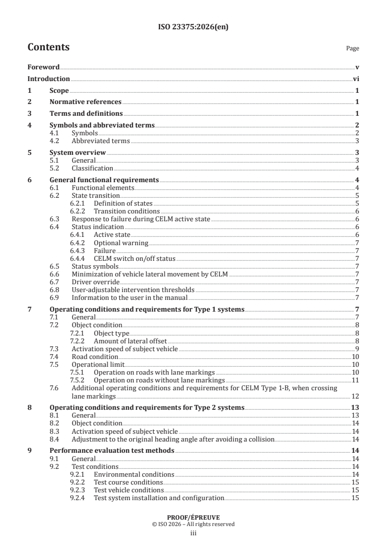
Contents Page
Foreword .v
Introduction .vi
1 Scope . 1
2 Normative references . 1
3 Terms and definitions . 1
4 Symbols and abbreviated terms. 2
4.1 Symbols .2
4.2 Abbreviated terms .3
5 System overview . 3
5.1 General .3
5.2 Classification .4
6 General functional requirements . 4
6.1 Functional elements.4
6.2 State transition .5
6.2.1 Definition of states .5
6.2.2 Transition conditions .6
6.3 Response to failure during CELM active state .6
6.4 Status indication .6
6.4.1 Active state .6
6.4.2 Optional warning .7
6.4.3 Failure .7
6.4.4 CELM switch on/off status .7
6.5 Status symbols .7
6.6 Minimization of vehicle lateral movement by CELM .7
6.7 Driver override .7
6.8 User-adjustable intervention thresholds .7
6.9 Information to the user in the manual .7
7 Operating conditions and requirements for Type 1 systems . 7
7.1 General .7
7.2 Object condition . .8
7.2.1 Object type .8
7.2.2 Amount of lateral offset .8
7.3 Activation speed of subject vehicle .9
7.4 Road condition .10
7.5 Operational limit .10
7.5.1 Operation on roads with lane markings .10
7.5.2 Operation on roads without lane markings .11
7.6 Additional operating conditions and requirements for CELM Type 1-B, when crossing
lane markings . 12
8 Operating conditions and requirements for Type 2 systems .13
8.1 General . 13
8.2 Object condition . .14
8.3 Activation speed of subject vehicle .14
8.4 Adjustment to the original heading angle after avoiding a collision .14
9 Performance evaluation test methods . 14
9.1 General .14
9.2 Test conditions .14
9.2.1 Environmental conditions .14
9.2.2 Test course conditions . 15
9.2.3 Test vehicle conditions . 15
9.2.4 Test system installation and configuration. 15
PROOF/ÉPREUVE
iii
9.2.5 Data recording . 15
9.2.6 Test target. 15
9.3 Type 1 test procedures .16
9.3.1 Test case selection .16
9.3.2 Test parameters .16
9.3.3 Test target selection and positioning .18
9.3.4 Test procedures .21
9.3.5 Pass criteria . 22
9.4 Additional Type 1-B Test procedures . 22
9.4.1 Test case selection . 22
9.4.2 Test parameters and target positioning . 23
9.4.3 Test target selection .24
9.4.4 Test procedures .24
9.4.5 Pass criteria . 25
9.5 Type 2 test procedures . 25
9.5.1 Test equipment . 25
9.5.2 Trajectory and torque data . 26
9.5.3 Test procedure for collision avoidance performance . 28
9.5.4 Pass criteria for collision avoidance performance . 29
9.5.5 Test procedure for adjustment to the original heading angle performance (Type
2-A) . 29
9.5.6 Pass criteria for adjustment to the original heading angle performance (Type
2-A) . 30
9.5.7 Test procedure for adjustment to the original heading angle performance (Type
2-B) .31
9.5.8 Pass criteria for adjustment to the original heading angle performance (Type
2-B) .31
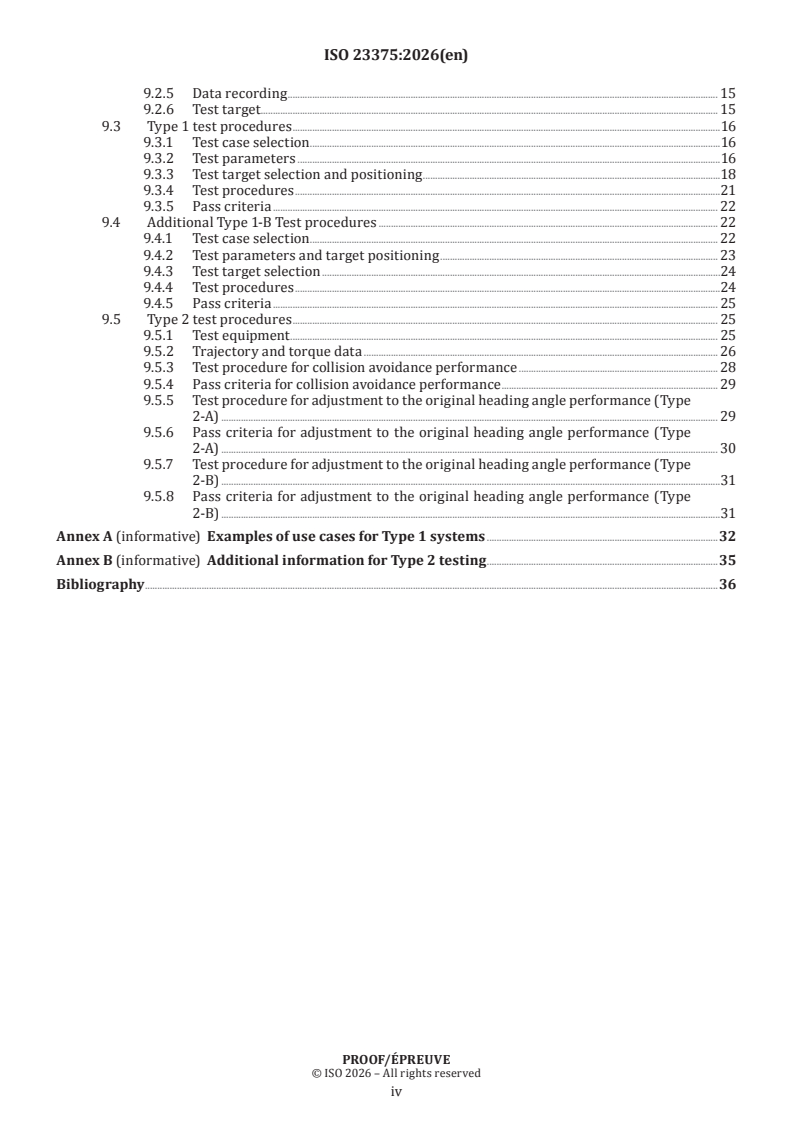
Annex A (informative) Examples of use cases for Type 1 systems .32
Annex B (informative) Additional information for Type 2 testing .35
Bibliography .36
PROOF/ÉPREUVE
iv
Foreword
ISO (the International Organization for Standardization) is a worldwide federation of national standards
bodies (ISO member bodies). The work of preparing International Standards is normally carried out through
ISO technical committees. Each member body interested in a subject for which a technical committee
has been established has the right to be represented on that committee. International organizations,
governmental and non-governmental, in liaison with ISO, also take part in the work. ISO collaborates closely
with the International Electrotechnical Commission (IEC) on all matters of electrotechnical standardization.
The procedures used to develop this document and those intended for its further maintenance are described
in the ISO/IEC Directives, Part 1. In particular, the different approval criteria needed for the different types
of ISO document should be noted. This document was drafted in accordance with the editorial rules of the
ISO/IEC Directives, Part 2 (see www.iso.org/directives).
ISO draws attention to the possibility that the implementation of this document may involve the use of (a)
patent(s). ISO takes no position concerning the evidence, validity or applicability of any claimed patent
rights in respect thereof. As of the date of publication of this document, ISO had not received notice of (a)
patent(s) which may be required to implement this document. However, implementers are cautioned that
this may not represent the latest information, which may be obtained from the patent database available at
www.iso.org/patents. ISO shall not be held responsible for identifying any or all such patent rights.
Any trade name used in this document is information given for the convenience of users and does not
constitute an endorsement.
For an explanation of the voluntary nature of standards, the meaning of ISO specific terms and expressions
related to conformity assessment, as well as information about ISO's adherence to the World Trade
Organization (WTO) principles in the Technical Barriers to Trade (TBT), see www.iso.org/iso/foreword.html.
This document was prepared by Technical Committee ISO/TC 204, Intelligent transport systems.
This second edition cancels and replaces the first edition (ISO 23375:2023), which has been technically
revised.
The main changes are as follows:
— extended with performance requirements and test procedures for a type of Automatic Collision Evasive
Lateral Manoeuvre (CELM) system that permits lane crossing under specified conditions;
— included performance requirements and a test procedure for the original heading angle adjustment
function for a type of driver-initiated Collision Evasive Lateral Manoeuvre (CELM) system.
Any feedback or questions on this document should be directed to the user’s national standards body. A
complete listing of these bodies can be found at www.iso.org/members.html.
PROOF/ÉPREUVE
v
Introduction
Reducing traffic fatalities, injuries and property damage caused by driver carelessness or unexpected
events is a global challenge. To address this situation, automatic emergency braking (AEB) systems were
introduced to mitigate crash consequences through automatic deceleration by braking of the vehicle.
NOTE ISO 22839 and ISO 19237 are examples of related International Standards defining the minimum
performance requirements of such systems. The ISO 22733 series defines test procedures to evaluate the performance
level of such systems.
These AEB systems work effectively when there is a high probability of a collision, but their operation can
be limited, or they can potentially not work at all, when there is a low probability of a collision (e.g. when the
degree of overlap to the object is small). However, even in such scenarios, there are cases where a collision
can be avoided by system support, i.e. by a small amount of lateral movement.
This document defines functional requirements, minimum performance requirements and test procedures
to verify these requirements for collision avoidance systems using lateral movement of the vehicle, i.e. a
collision evasive lateral manoeuvre system (CELM).
A CELM is a safety system aimed at supporting the driver’s vehicle operation by avoiding collisions with
objects in the forward path of the vehicle. When a collision is predicted, the CELM controls lateral movement
of the vehicle by generating yaw moment.
The lateral control manoeuvres can be performed automatically by CELM or can be initiated by the driver
and supported by CELM.
PROOF/ÉPREUVE
vi
International Standard ISO 23375:2026(en)
Intelligent transport systems — Collision evasive lateral
manoeuvre systems (CELM) — Requirements and test
procedures
1 Scope
This document specifies basic control strategies, minimum functional requirements, basic driver interface
elements, and test procedures for verifying the system requirements for collision evasive lateral manoeuvre
systems (CELM).
Specific methods for object detection and other environmental perception technologies are not described in
this document.
[1] [1]
This document applies to light vehicles and heavy trucks . Vehicles equipped with trailers are not within
the scope of this document.
2 Normative references
The following documents are referred to in the text in such a way that some or all of their content constitutes
requirements of this document. For dated references, only the edition cited applies. For undated references,
the latest edition of the referenced document (including any amendments) applies.
FMVSS 105:2026, Hydraulic and Electric Brake Systems
ISO 19206-2, Road vehicles — Test devices for target vehicles, vulnerable road users and other objects, for
assessment of active safety functions — Part 2: Requirements for pedestrian targets
ISO 19206-3, Road vehicles — Test devices for target vehicles, vulnerable road users and other objects, for
assessment of active safety functions — Part 3: Requirements for passenger vehicle 3D targets
ISO 17387, Intelligent transport systems — Lane change decision aid systems (LCDAS) — Performance
requirements and test procedures
3 Terms and definitions
For the purposes of this document, the following terms and definitions apply.
ISO and IEC maintain terminology databases for use in standardization at the following addresses:
— ISO Online browsing platform: available at https:// www .iso .org/ obp
— IEC Electropedia: available at https:// www .electropedia .org/
3.1
subject vehicle
SV
vehicle equipped with a collision evasive lateral manoeuvre system (CELM)
3.2
object
obstacle that can represent a hazard if hit by the subject vehicle (3.1)
PROOF/ÉPREUVE
3.3
lane marking
delineator, marking or Botts’ dot intentionally placed on the borderline of the lane
3.4
lane boundary
outer edge of the lane marking (3.3)
3.5
system failure
inability of a system or system component to perform a required function within specified limits, which is
caused by mechanical or electronic malfunction
3.6
subject vehicle direction
SV direction
direction of travel of the subject vehicle (3.1) used to predict a collision
3.7
time to collision
TTC
time that it will take a subject vehicle (3.1) to collide with an object assuming constant relative velocity
3.8
critical approach
driving situation which leads to an imminent collision if no driver or system prevention reaction occurs
3.9
highway
type of road where pedestrians and cyclists are prohibited and which, by design, is equipped with a physical
separation that divides the traffic moving in opposite directions
3.10
ego lane
lane in which the subject vehicle (3.1) is currently travelling
4 Symbols and abbreviated terms
4.1 Symbols
Symbols used in this document and their meanings are described in Table 1.
PROOF/ÉPREUVE
Table 1 — Symbols and meanings
Symbol Meaning Unit
V Speed of the SV. m/s
SV
V Minimum SV speed for CELM operation. m/s
min
V Maximum SV speed for CELM operation. m/s
max
V The mean of lateral speed of the SV orthogonal m/s
svL
to the lane markings, i.e. the y-axis component of
vehicle motion when travelling parallel to the lane
markings (see 9.3.3.3 for details).
L Lateral distance between the outermost edge of the m
d
object and the extension of the side of the SV closest
to the object when measured parallel to the SV (i.e.
point at which the distance becomes minimum).
A positive value refers to a situation where an over-
lap exists between the SV and object.
A negative value refers to a situation where an over-
lap does not exist between the SV and object.
See 7.2.2 for details.
L Distance between the edge of an object and the m
d_inner
inner edge of lane marking, when the object is locat-
ed inside the ego lane of the SV.
L Distance between the edge of an object and the m
d_outer
outer edge of lane marking, when the object is locat-
ed outside the ego lane of the SV.
L Minimum amount of lateral offset to which the sys- m
ofst_min
tem is designed to respond.
L Maximum amount of lateral offset to which the m
ofst_max
system is designed to respond.
x Minimum longitudinal distance for which the angle m
c_min
between the SV and an object shall be constant
when the SV approaches a test target.
L Permissible range of lateral movement. m
dsv
4.2 Abbreviated terms
AEB automatic emergency braking
CELM collision evasive lateral manoeuvre system
LDP lane departure prevention
TTC time to collision
GNSS Global Navigation Satellite System
5 System overview
5.1 General
The CELM detects objects in the front area in the current SV direction of travel.
The CELM determines objects as hazardous if they are predicted to be in the driving path of the SV and a
collision with the object is imminent.
The CELM activates actuators (e.g. steering, brake) to generate yaw moment in an attempt to avoid a collision.
PROOF/ÉPREUVE
The CELM controls or supports the lateral movement of the SV in the direction which avoids the collision in
the best manner or which has been chosen by the driver.
The CELM may operate under conditions where AEB systems are activated.
When the CELM is initiating, performing or terminating evasive manoeuvres, the vehicle remains
controllable by the driver.
5.2 Classification
CELMs are classified into two types as shown in Table 2.
Table 2 — Type classification
Types Initiation Description
Type 1 Automatic — The evasive manoeuvre is performed automatically by the system
(See Clause 7 for details).
— Amount of lateral movement is restricted.
Type 1-A: The evasive manoeuvre shall be performed within the lane of the
subject vehicle.
Type 1-B (optional): Additionally, the evasive manoeuvre may continue to
be in effect - crossing the lane marking only if the requirements in 7.6 can
be met.
Type 2 Driver trigger — The driver performs the evasive manoeuvre. The system supports
the driver (See Clause 8 for details).
— No restriction on the amount of lateral movement.
6 General functional requirements
6.1 Functional elements
The CELM shall be designed taking into consideration the functional elements shown in Figure 1.
Output to the brake actuator (e.g. activation of AEB systems) can potentially improve avoidance performance.
However, the implementation methods for such a combination are not described in this document.
Key
common elements for both types
type specific elements
Figure 1 — Functional elements
PROOF/ÉPREUVE
6.2 State transition
A CELM shall operate according to the state transition diagram shown in Figure 2. Specific implementation
beyond that which is illustrated in Figure 2 is left to the discretion of the manufacturer.
The transition diagram in Figure 2 is applicable to both Type 1 and Type 2 systems. However, conditions for
transition 3 and transition 4 are different.
Key
1 (Propulsion runcycle on 4 Driver override condition satisfied
and no system failure) or evasive manoeuvre is completed
or
(CELM on/off switch is manually turned on, if applicable
and no system failure)
2 System failure 5 System failure
or propulsion run cycle off or propulsion run cycle off
or CELM on/off switch is manually turned off, if applicable
3 Type 1
— critical approach is predicted
— and V ≤ V ≤ V
min sv max
— and other criteria specified by manufacturer (optionally)
Type 2
— system predicts a critical approach to an object
— and the driver initiates an evasive manoeuvre
— and V ≤ V ≤ V
min sv max
— and other criteria specified by manufacturer (optionally)
Figure 2 — State transition diagram
6.2.1 Definition of states
6.2.1.1 CELM off state
State in which the CELM is not ready for activation.
6.2.1.2 CELM stand-by state
State in which the system is ready for activation.
6.2.1.3 CELM active state
State in which the system is activated. Operating conditions and requirements defined in Clause 7 (for
Type 1) or Clause 8 (for Type 2) and manufacturer-defined collision prediction conditions and minimum
functional requirements shall be satisfied.
PROOF/ÉPREUVE
6.2.2 Transition conditions
6.2.2.1 Transition from CELM off to CELM stand-by (key element 1 of Figure 2)
The system shall transition from CELM off state to CELM stand-by state with the conditions of propulsion
run cycle on and no system failure. If the system is equipped with a CELM on/off switch, it shall transition
from CELM off state to CELM stand-by state with the conditions of propulsion run cycle on, no system failure.
6.2.2.2 Transition from CELM stand-by to CELM off (key element 2 of Figure 2)
The system shall transition from CELM stand-by state to CELM off state with the conditions of system failure
or propulsion run cycle off. If the system is equipped with a CELM on/off switch, it shall transition from
CELM stand-by state to CELM off state when the driver deactivates CELM with the switch.
6.2.2.3 Transition from CELM stand-by to CELM active (key element 3 of Figure 2)
6.2.2.3.1 Type 1 systems
The system shall transition from CELM stand-by to CELM active state when the system predicts a collision,
no driver avoidance operation is detected, and operating conditions and requirements defined in Clause 7
are satisfied.
NOTE See Annex A for examples of use cases of Type 1 systems.
6.2.2.3.2 Type 2 systems
The system shall transition from CELM stand-by to CELM active state when the system predicts a critical
approach, the driver initiates an evasive manoeuvre, and operating conditions and requirements defined in
Clause 8 are satisfied.
6.2.2.4 Transition from CELM active to CELM stand-by state (key element 4 of Figure 2)
The system shall transition from CELM active state to CELM stand-by state when the evasive manoeuvre is
completed, or the driver overrides the system.
6.2.2.5 Transition from CELM active to CELM off (key element 5 of Figure 2)
The system shall transition from CELM active state to CELM off state with the conditions of system failure
or propulsion run cycle off. It is recommended for the transition to result in a gradual change of the yaw
moment control.
6.3 Response to failure during CELM active state
Occurrence of a system failure during CELM active state should not result in conditions uncontrollable by
the driver. Yaw moment control should fade out gradually.
6.4 Status indication
6.4.1 Active state
The system shall provide information to the driver when the system is in active state.
If the vehicle is equipped with AEB and/or lane departure prevention (LDP) systems, the display device may
be commonly used to indicate the active state of multiple systems.
The driver shall be provided with an indication of active state. Specific implementation of the indication is
left to the manufacturer.
PROOF/ÉPREUVE
6.4.2 Optional warning
When the system has detected probability of a collision exceeding the defined threshold, the CELM may
provide a driver with a warning to suggest evasive manoeuvres. If the vehicle is equipped with AEB and/or
LDP systems, the display device may be shared to provide this optional warning.
6.4.3 Failure
The driver shall be provided with an indication of system failure. Specific implementation of the indication
is left to the manufacturer.
6.4.4 CELM switch on/off status
If the system is equipped with a CELM on/off switch, it shall be possible for the driver to determine the
status of the switch (i.e. on or off) whenever needed.
6.5 Status symbols
Status symbols to indicate CELM function or malfunction may be specified by the manufacturer. Standardized
symbols in accordance with ISO 2575 may be used.
6.6 Minimization of vehicle lateral movement by CELM
Lateral movement should be limited so that the SV passes the object as close as possible while still
maintaining a sufficient clearance to reliably avoid a collision.
6.7 Driver override
The driver shall be provided with the means to override the system operation at any time. Such means shall
include steering wheel operation, for example:
— steering wheel operation with strong torque;
— continuing to maintain the steering angle;
— turning the steering wheel in the opposite direction to the CELM’s assistance.
Brake intervention during CELM active state should not be considered as an override. It is out-of-CELM-
scope.
6.8 User-adjustable intervention thresholds
CELM may be equipped with a user-adjustable switch to change intervention thresholds, such as the point
in time to issue a warning, the point in time to transition to CELM active state, or the degree of yaw moment
control during CELM active state.
6.9 Information to the user in the manual
Manufacturers shall provide the user with a general description of the system functionalities and limitations
in the user’s manual.
7 Operating conditions and requirements for Type 1 systems
7.1 General
Type 1 systems support the driver in an approach situation where a collision with an object is imminent.
If the driver does not react, the system shall perform an automatic evasive manoeuvre when physical
PROOF/ÉPREUVE
conditions (e.g. road friction, geometry) allow. CELM determines the evasive driving direction (left/right)
and, when the physical conditions allow, calculates a path to avoid a collision with the object.
During the evasive manoeuvre CELM Type 1 shall not cross the lane marking (outer edge of the front tyre to
outer edge of the lane marking). The evasive manoeuvre may continue to be in effect after crossing the lane
marking only if the requirements in 7.6 can be met.
The system shall control the SV position and orientation with respect to the lane so that the SV heading
angle is as parallel as possible to the tangent of the lane when an evasive manoeuvre is complete. However,
the heading angle requirement does not apply if the SV comes to a stop during the evasive manoeuvre.
If there are no lane markings, the maximum allowable lateral movement is limited.
7.2 Object condition
7.2.1 Object type
The manufacturer shall define the type of objects to which the system shall respond. At a minimum,
Type 1 systems shall respond to a stationary pedestrian or a stationary vehicle. Further augmentation of
the system to respond to moving objects or other types of stationary objects is left to the discretion of the
manufacturer. However, this document does not specify performance requirements for such augmented
systems with enhanced performance.
7.2.2 Amount of lateral offset
Type 1 systems shall operate, at a minimum, under conditions where an overlap exists between the object
and SV. The relative lateral positions between the SV and object where CELM activates (i.e. values of L
ofst_min
and L ) shall be defined by the manufacturer.
ofst_max
Figure 3 illustrates the relative lateral positions between the SV and object where the object is within the
range for system operation.
Depending on the system design, L may be a negative value, meaning that the object is outside of
ofst_min
the extension of the vehicle width, but can still be determined by CELM that a collision is imminent. This
condition is illustrated in Figure 3 b).
PROOF/ÉPREUVE
a) Overlap exists b) Overlap does not exist
Key
1 outermost edge of SV
2 outermost edge of object
3 L
ofst_min
4 L
ofst_max
5 extension of SV width (object side)
6 extension of outermost edge of object
7 L
d
Figure 3 — Amount of lateral offset
7.3 Activation speed of subject vehicle
Type 1 systems can be further classified by activation speed as shown in Table 3.
For example, systems primarily intended to be used on urban/city roads are in the low-speed category and
systems primarily intended to be used on highway/motorways are in the high-speed category.
V and V shall be defined by the manufacturer.
min max
The difference between V and V of each CELM shall be greater than 5,5 m/s and include at least the
min max
range shown in Table 3.
PROOF/ÉPREUVE
Table 3 — Minimum activation speed range of SV
Examples of possible activation speed ranges
Categories Minimum required ranges
V V Difference
min max
Low speed V ≤ 12 m/s 7,5 m/s 13 m/s 5,5 m/s
min
V ≥ 13 m/s
max 12 m/s 17,5 m/s 5,5 m/s
5 m/s 15 m/s 10 m/s
High speed V ≤ 17 m/s 17 m/s 22,5 m/s 5,5 m/s
min
V ≥ 20 m/s
14,5 m/s 20 m/s 5,5 m/s
max
15 m/s 25 m/s 10 m/s
7.4 Road condition
As a minimum requirement, Type 1 systems shall operate on roads with visible lane markings.
Optionally, Type 1 systems may also operate on roads without lane markings.
7.5 Operational limit
7.5.1 Operation on roads with lane markings
In situations where the system operates on roads with lane markings, its lateral control shall be performed
within the SV’s own lane, unless the system is capable of fulfilling the requirements of paragraph 7.6.
Therefore, allowable lateral movement for evasive manoeuvre is limited to the lane boundary on the
avoidance side, which means that the body of the SV (excluding side view mirrors) shall not cross over the
lane boundary (outer edge of the lane marking). Figure 4 illustrates the lane boundary and the allowable
lateral movement of SV.
PROOF/ÉPREUVE
Key
1 allowable range of lateral movement
2 vehicle trajectory
3 object
4 lane markings
5 outermost edge of SV excluding side view mirrors
6 lane boundary (outer edge of the lane marking)
NOTE This figure shows an example of collision avoidance to the right. However, it can be applied to collision
avoidance in both directions (right and left).
Figure 4 — Lane boundary and allowable lateral movement of SV
7.5.2 Operation on roads without lane markings
In situations where the system operates without lane markings, the permissible range of lateral movement
of the SV should not exceed 0,75 m with respect to the extension of the path of the SV, unless the system is
capable of fulfilling the requirements of paragraph 7.6. Figure 5 illustrates the recommended permissible
lateral movement.
PROOF/ÉPREUVE
a) Avoidance to the right b) Avoidance to the left
Key
1 object
2 recommended allowable lateral movement
3 extension of the path of the SV
4 travelling path with CELM
Figure 5 — Recommended allowable lateral movement
7.6 Additional operating conditions and requirements for CELM Type 1-B, when crossing
lane markings
A CELM Type 1-B is permitted to cross lane markings, if the system fulfils following requirements where
applicable to the design of the system and relevant to the safety concept:
— The vehicle shall be controllable by the driver during the manoeuvre at any time. Lateral thresholds shall
be within the vehicle capability for safe driving in nominal road conditions.
— The system shall only initiate an automatic evasive manoeuvre if a drivable space of sufficient width and
length is available in the target area, which is free of detected road users or stationary obstacles within
the system’s detection capability.
— Crossing lane markings is only permissible if the detected vehicles in the adjacent lane of interest will not
be forced to decelerate unmanageably or take evasive steering action due to the manoeuvre.
Detection area front adjacent lane which is relevant for CELM manoeuvre: The searchable detection
area shall be long and wide enough to cover the duration from the time the subject vehicle starts the
CELM countermeasure to the time it completes it.
Detection area rear adjacent lane which is relevant for CELM manoeuvre: The searchable detection area
shall be long and wide enough to cover the duration from the time the subject vehicle starts the CELM
countermeasure to the time it completes it.
Detection area front adjacent lane which is relevant for CELM manoeuvre: The searchable detection
area shall be long and wide enough to cover the duration from the time the subject vehicle starts the
CELM countermeasure to the time it completes it in the oncoming adjacent lane and then moves away
from the oncoming traffic path as much as possible (possibly returning to its original lane).
— Potential risk with oncoming vehicles should be accounted for to mitigate the risk of secondary crash
situations e.g. check for sufficient space for oncoming traffic and subject vehicle to brake or space to
steer the subject vehicle back in its original lane of travel.
PROOF/ÉPREUVE
— Lateral movement should be limited to the minimum necessary to ensure safe collision prevention, while
maintaining sufficient space for any traffic in the adjacent lane.
— CELM shall not move further into the adjacent lane, if a crash relevant object is detected in the adjacent
lane, after the SV started to cross the lane markings.
— The subject vehicle shall not leave the road.
— The evasive manoeuvre shall primarily be performed within the lane of the subject vehicle. However, if
the system has sufficient information about its surroundings including:
— the front, side and rear, and
— type of lane markings or road signs
to assess the criticality of crossing lane markings, crossing the lane markings may be executed when an
imminent collision risk is present.
— An evasive lane crossing shall be indicated to other road users. When initiating an evasive lane crossing
that intends to cross into the evading lane by more than 30 cm, the system shall indicate its intention to
change into the evading lane by generating the signal to activate the direction indicator.
— The system monitors the traffic situation in the adjacent lane at least in the blind spot and closing range.
Means to detect the blind spot and closing range shall conform to the requirements of LCDAS Type III C
specified in ISO 17387.
— The manufacturer
...
ISO/DISPRF 23375:2025(en)
Date: 2025-10-04
ISO/TC 204/WG 14
Secretariat: ANSI
Date: 2026-07-17
Intelligent transport systems — Collision evasive lateral manoeuvre
systems (CELM) — Requirements and test procedures
Systèmes de transport intelligents — Systèmes de manœuvre latérale d'évitement de collision (CELM) —
Exigences et procédures d'essai
PROOF
ISO/PRF 23375:2026(en)
All rights reserved. Unless otherwise specified, or required in the context of its implementation, no part of this publication
may be reproduced or utilized otherwise in any form or by any means, electronic or mechanical, including photocopying,
or posting on the internet or an intranet, without prior written permission. Permission can be requested from either ISO
at the address below or ISO’s member body in the country of the requester.
ISO copyright office
CP 401 • Ch. de Blandonnet 8 • CP 401
CH-1214 Vernier, Geneva, Switzerland
Tel.Phone: + 41 22 749 01 11
Fax + 41 22 749 09 47
E-mail: copyright@iso.org
Website: www.iso.org
Published in Switzerland
ii
ISO/PRF 23375:2026(en)
Contents
Foreword . iv
Introduction . v
1 Scope . 1
2 Normative references . 1
3 Terms and definitions . 1
4 Symbols and abbreviated terms . 2
4.1 Symbols . 2
4.2 Abbreviated terms . 3
5 System overview . 3
5.1 General. 3
5.2 Classification. 4
6 General functional requirements . 4
6.1 Functional elements . 4
6.2 State transition . 5
6.3 Response to failure during CELM active state . 7
6.4 Status indication. 7
6.5 Status symbols . 8
6.6 Minimization of vehicle lateral movement by CELM . 8
6.7 Driver override . 8
6.8 User-adjustable intervention thresholds . 8
6.9 Information to the user in the manual . 8
7 Operating conditions and requirements for Type 1 systems . 8
7.1 General. 8
7.2 Object condition . 9
7.3 Activation speed of subject vehicle . 10
7.4 Road condition . 11
7.5 Operational limit . 11
7.6 Additional operating conditions and requirements for CELM Type 1-B, when crossing
lane markings . 14
8 Operating conditions and requirements for Type 2 systems . 15
8.1 General. 15
8.2 Object condition . 16
8.3 Activation speed of subject vehicle . 16
8.4 Adjustment to the original heading angle after avoiding a collision . 16
9 Performance evaluation test methods . 16
9.1 General. 16
9.2 Test conditions . 17
9.3 Type 1 test procedures . 18
9.4 Additional Type 1-B Test procedures . 29
9.5 Type 2 test procedures . 32
Annex A (informative) Examples of use cases for Type 1 systems . 41
Annex B (informative) Additional information for Type 2 testing . 46
Bibliography . 47
iii
ISO/PRF 23375:2026(en)
Foreword
ISO (the International Organization for Standardization) is a worldwide federation of national standards
bodies (ISO member bodies). The work of preparing International Standards is normally carried out through
ISO technical committees. Each member body interested in a subject for which a technical committee has been
established has the right to be represented on that committee. International organizations, governmental and
non-governmental, in liaison with ISO, also take part in the work. ISO collaborates closely with the
International Electrotechnical Commission (IEC) on all matters of electrotechnical standardization.
The procedures used to develop this document and those intended for its further maintenance are described
in the ISO/IEC Directives, Part 1. In particular, the different approval criteria needed for the different types of
ISO documentsdocument should be noted. This document was drafted in accordance with the editorial rules
of the ISO/IEC Directives, Part 2 (see www.iso.org/directives).
Attention is drawnISO draws attention to the possibility that some of the elementsimplementation of this
document may beinvolve the subjectuse of (a) patent(s). ISO takes no position concerning the evidence,
validity or applicability of any claimed patent rights in respect thereof. As of the date of publication of this
document, ISO had not received notice of (a) patent(s) which may be required to implement this document.
However, implementers are cautioned that this may not represent the latest information, which may be
obtained from the patent database available at www.iso.org/patents. ISO shall not be held responsible for
identifying any or all such patent rights. Details of any patent rights identified during the development of the
document will be in the Introduction and/or on the ISO list of patent declarations received (see ).
Any trade name used in this document is information given for the convenience of users and does not
constitute an endorsement.
For an explanation of the voluntary nature of standards, the meaning of ISO specific terms and expressions
related to conformity assessment, as well as information about ISO's adherence to the World Trade
Organization (WTO) principles in the Technical Barriers to Trade (TBT), see www.iso.org/iso/foreword.html.
This document was prepared by Technical Committee ISO/TC 204, Intelligent transport systems.
This second edition cancels and replaces the first edition (ISO 23375:2023), which has been technically
revised.
The main changes are as follows:
— — the second edition of ISO 23375 is extended with performance requirements and test procedures for
a type of Automatic Collision Evasive Lateral Manoeuvre (CELM) system that permits lane crossing under
specified conditions.;
— — additionally, this document includesincluded performance requirements and a test procedure for the
original heading angle adjustment function for a type of driver-initiated Collision Evasive Lateral
Manoeuvre (CELM) system.
Any feedback or questions on this document should be directed to the user’s national standards body. A
complete listing of these bodies can be found at www.iso.org/members.html.
iv
ISO/PRF 23375:2026(en)
Introduction
Reducing traffic fatalities, injuries and property damage caused by driver carelessness or unexpected events
is a global challenge. To address this situation, automatic emergency braking (AEB) systems were introduced
to mitigate crash consequences through automatic deceleration by braking of the vehicle.
NOTE ISO 22839 and ISO 19237 are examples of related International Standards defining the minimum
performance requirements of such systems. The ISO 22733 series defines test procedures to evaluate the performance
level of such systems.
These AEB systems work effectively when there is a high probability of a collision, but their operation can be
limited, or they can potentially not work at all, when there is a low probability of a collision (e.g. when the
degree of overlap to the object is small). However, even in such scenarios, there are cases where a collision
can be avoided by system support, i.e. by a small amount of lateral movement.
This document defines functional requirements, minimum performance requirements and test procedures to
verify these requirements for collision avoidance systems using lateral movement of the vehicle, i.e. a collision
evasive lateral manoeuvre system (CELM).
A CELM is a safety system aimed at supporting the driver’s vehicle operation by avoiding collisions with
objects in the forward path of the vehicle. When a collision is predicted, the CELM controls lateral movement
of the vehicle by generating yaw moment.
The lateral control manoeuvres can be performed automatically by CELM or can be initiated by the driver and
supported by CELM.
v
ISO/PRF 23375:2026(en)
Intelligent transport systems — Collision evasive lateral manoeuvre
systems (CELM) — Requirements and test procedures
1 Scope
This document specifies basic control strategies, minimum functional requirements, basic driver interface
elements, and test procedures for verifying the system requirements for collision evasive lateral manoeuvre
systems (CELM).
Specific methods for object detection and other environmental perception technologies are not described in
this document.
[1][1] [1][1]
This document applies to light vehicles and heavy trucks . Vehicles equipped with trailers are not
within the scope of this document.
2 Normative references
The following documents are referred to in the text in such a way that some or all of their content constitutes
requirements of this document. For dated references, only the edition cited applies. For undated references,
the latest edition of the referenced document (including any amendments) applies.
FMVSS 105:2026, Hydraulic and Electric Brake Systems
ISO 19206--2, Road vehicles — Test devices for target vehicles, vulnerable road users and other objects, for
assessment of active safety functions — Part 2: Requirements for pedestrian targets
ISO 19206--3, Road vehicles — Test devices for target vehicles, vulnerable road users and other objects, for
assessment of active safety functions — Part 3: Requirements for passenger vehicle 3D targets
ISO 17387:2008, Intelligent transport systems — Lane change decision aid systems (LCDAS) — Performance
requirements and test procedures
3 Terms and definitions
For the purposes of this document, the following terms and definitions apply.
ISO and IEC maintain terminology databases for use in standardization at the following addresses:
— — ISO Online browsing platform: available at https://www.iso.org/obp
— — IEC Electropedia: available at https://www.electropedia.org/
3.1 3.1
subject vehicle
SV
vehicle equipped with a collision evasive lateral manoeuvre system (CELM)
3.2 3.2
object
obstacle that couldcan represent a hazard if hit by the subject vehicle (3.1(3.1))
3.3 3.3
lane marking
delineator, marking or Botts’ dot intentionally placed on the borderline of the lane
ISO/PRF 23375:2026(en)
3.4 3.4
lane boundary
outer edge of the lane marking (3.3(3.3))
3.5 3.5
system failure
inability of a system or system component to perform a required function within specified limits, which is
caused by mechanical or electronic malfunction
3.6 3.6
subject vehicle direction
SV direction
direction of travel of the subject vehicle (3.1(3.1)) used to predict a collision
3.7 3.7
time to collision
TTC
time that it will take a subject vehicle (3.1(3.1)) to collide with an object assuming constant relative velocity
3.8 3.8
critical approach
driving situation which leads to an imminent collision if no driver or system prevention reaction occurs
3.9 3.9
highway
type of road where pedestrians and cyclists are prohibited and which, by design, is equipped with a physical
separation that divides the traffic moving in opposite directions
3.10 3.10
ego lane
lane in which the subject vehicle (3.1(3.1)) is currently travelling
4 Symbols and abbreviated terms
4.1 Symbols
Symbols used in this document and their meanings are described in Table 1Table 1.
Table 1 — Symbols and meanings
Symbol Meaning Unit
VSV Speed of the SV. m/s
Vmin Minimum SV speed for CELM operation. m/s
V Maximum SV speed for CELM operation. m/s
max
VsvL The mean of lateral speed of the SV orthogonal to m/s
the lane markings, i.e. the y-axis component of
vehicle motion when travelling parallel to the lane
markings (see 9.3.3.3 for details).
Ld Lateral distance between the outermost edge of the m
object and the extension of the side of the SV
closest to the object when measured parallel to the
SV (i.e. point at which the distance becomes
minimum).
ISO/PRF 23375:2026(en)
Symbol Meaning Unit
A positive value refers to a situation where an
overlap exists between the SV and object.
A negative value refers to a situation where an
overlap does not exist between the SV and object.
See 7.2.2 for details.
L Distance between the edge of an object and the m
d_inner
inner edge of lane marking, when the object is
located inside the ego lane of the SV.
L Distance between the edge of an object and the m
d_outer
outer edge of lane marking, when the object is
located outside the ego lane of the SV.
L Minimum amount of lateral offset to which the m
ofst_min
system is designed to respond.
L Maximum amount of lateral offset to which the m
ofst_max
system is designed to respond.
x Minimum longitudinal distance for which the angle m
c_min
between the SV and an object shall be constant
when the SV approaches a test target.
L Permissible range of lateral movement. m
dsv
4.2 Abbreviated terms
AEB automatic emergency braking
CELM collision evasive lateral manoeuvre system
LDP lane departure prevention
TTC time to collision
GNSS Global Navigation Satellite System
5 System overview
5.1 General
The CELM detects objects in the front area in the current SV direction of travel.
The CELM determines objects as hazardous if they are predicted to be in the driving path of the SV and a
collision with the object is imminent.
The CELM activates actuators (e.g. steering, brake) to generate yaw moment in an attempt to avoid a collision.
The CELM controls or supports the lateral movement of the SV in the direction which avoids the collision in
the best manner or which has been chosen by the driver.
The CELM may operate under conditions where AEB systems are activated.
When the CELM is initiating, performing or terminating evasive manoeuvres, the vehicle remains controllable
by the driver.
ISO/PRF 23375:2026(en)
5.2 Classification
CELMs are classified into two types as shown in Table 2Table 2.
Table 2 — Type classification
Types Initiation Description
— The evasive manoeuvre is performed automatically by the system
Type 1 Automatic
(See Clause 7 for details).
— Amount of lateral movement is restricted.
Type 1-A: The evasive manoeuvre shall be performed within the lane of the
subject vehicle.
Type 1-B (optional): Additionally, the evasive manoeuvre may continue to
be in effect - crossing the lane marking only if the requirements in 7.6 can
be met.
— The driver performs the evasive manoeuvre. The system supports
Type 2 Driver trigger
the driver (See Clause 8 for details).
— No restriction on the amount of lateral movement.
6 General functional requirements
6.1 Functional elements
The CELM shall be designed taking into consideration the functional elements shown in Figure 1Figure 1.
Output to the brake actuator (e.g. activation of AEB systems) can potentially improve avoidance performance.
However, the implementation methods for such a combination are not described in this document.
ISO/PRF 23375:2026(en)
Key
common elements for both types
type specific elements
Figure 1 — Functional elements
6.2 State transition
A CELM shall operate according to the state transition diagram shown in Figure 2Figure 2. Specific
implementation beyond that which is illustrated in Figure 2Figure 2 is left to the discretion of the
manufacturer.
The transition diagram in Figure 2Figure 2 is applicable to both Type 1 and Type 2 systems. However,
conditions for transition 3 and transition 4 are different.
ISO/PRF 23375:2026(en)
Key
1 (Propulsion runcycle on 4 Driver override condition satisfied
and no system failure) or evasive manoeuvre is completed
or
(CELM on/off switch is manually turned on, if applicable
and no system failure)
2 System failure 5 System failure
or propulsion run cycle off or propulsion run cycle off
or CELM on/off switch is manually turned off, if applicable
3 Type 1
— critical approach is predicted
— and V ≤ V ≤ V
min sv max
— and other criteria specified by manufacturer (optionally)
Type 2
— system predicts a critical approach to an object
— and the driver initiates an evasive manoeuvre
— and Vmin ≤ Vsv ≤ Vmax
— and other criteria specified by manufacturer (optionally)
Figure 2 — State transition diagram
6.2.1 Definition of states
6.2.1.1 CELM off state
State in which the CELM is not ready for activation.
6.2.1.2 CELM stand-by state
State in which the system is ready for activation.
6.2.1.3 CELM active state
State in which the system is activated. Operating conditions and requirements defined in Clause 7Clause 7 (for
Type 1) or Clause 8Clause 8 (for Type 2) and manufacturer-defined collision prediction conditions and
minimum functional requirements shall be satisfied.
ISO/PRF 23375:2026(en)
6.2.2 Transition conditions
6.2.2.1 Transition from CELM off to CELM stand-by (key element 1 of Figure 2Figure 2))
The system shall transition from CELM off state to CELM stand-by state with the conditions of propulsion run
cycle on and no system failure. If the system is equipped with a CELM on/off switch, it shall transition from
CELM off state to CELM stand-by state with the conditions of propulsion run cycle on, no system failure.
6.2.2.2 Transition from CELM stand-by to CELM off (key element 2 of Figure 2Figure 2))
The system shall transition from CELM stand-by state to CELM off state with the conditions of system failure
or propulsion run cycle off. If the system is equipped with a CELM on/off switch, it shall transition from CELM
stand-by state to CELM off state when the driver deactivates CELM with the switch.
6.2.2.3 Transition from CELM stand-by to CELM active (key element 3 of Figure 2Figure 2))
6.2.2.3.1 Type 1 systems
The system shall transition from CELM stand-by to CELM active state when the system predicts a collision, no
driver avoidance operation is detected, and operating conditions and requirements defined in
Clause 7Clause 7 are satisfied.
NOTE See Annex AAnnex A for examples of use cases of Type 1 systems.
6.2.2.3.2 Type 2 systems
The system shall transition from CELM stand-by to CELM active state when the system predicts a critical
approach, the driver initiates an evasive manoeuvre, and operating conditions and requirements defined in
Clause 8Clause 8 are satisfied.
6.2.2.4 Transition from CELM active to CELM stand-by state (key element 4 of Figure 2Figure 2))
The system shall transition from CELM active state to CELM stand-by state when the evasive manoeuvre is
completed, or the driver overrides the system.
6.2.2.5 Transition from CELM active to CELM off (key element 5 of Figure 2Figure 2))
The system shall transition from CELM active state to CELM off state with the conditions of system failure or
propulsion run cycle off. It is recommended for the transition to result in a gradual change of the yaw moment
control.
6.3 Response to failure during CELM active state
Occurrence of a system failure during CELM active state should not result in conditions uncontrollable by the
driver. Yaw moment control should fade out gradually.
6.4 Status indication
6.4.1 Active state
The system shall provide information to the driver when the system is in active state.
If the vehicle is equipped with AEB and/or lane departure prevention (LDP) systems, the display device may
be commonly used to indicate the active state of multiple systems.
The driver shall be provided with an indication of active state. Specific implementation of the indication is left
to the manufacturer.
ISO/PRF 23375:2026(en)
6.4.2 Optional warning
When the system has detected probability of a collision exceeding the defined threshold, the CELM may
provide a driver with a warning to suggest evasive manoeuvres. If the vehicle is equipped with AEB and/or
LDP systems, the display device may be shared to provide this optional warning.
6.4.3 Failure
The driver shall be provided with an indication of system failure. Specific implementation of the indication is
left to the manufacturer.
6.4.4 CELM switch on/off status
If the system is equipped with a CELM on/off switch, it shall be possible for the driver to determine the status
of the switch (i.e. on or off) whenever needed.
6.5 Status symbols
Status symbols to indicate CELM function or malfunction may be specified by the manufacturer. Standardized
symbols in accordance with ISO 2575 may be used.
6.6 Minimization of vehicle lateral movement by CELM
Lateral movement should be limited so that the SV passes the object as close as possible while still maintaining
a sufficient clearance to reliably avoid a collision.
6.7 Driver override
The driver shall be provided with the means to override the system operation at any time. Such means shall
include steering wheel operation, for example:
— — steering wheel operation with strong torque;
— — continuing to maintain the steering angle;
— — turning the steering wheel in the opposite direction to the CELM’s assistance.
Brake intervention during CELM active state should not be considered as an override. It is out-of-CELM-scope.
6.8 User-adjustable intervention thresholds
CELM may be equipped with a user-adjustable switch to change intervention thresholds, such as the point in
time to issue a warning, the point in time to transition to CELM active state, or the degree of yaw moment
control during CELM active state.
6.9 Information to the user in the manual
Manufacturers shall provide the user with a general description of the system functionalities and limitations
in the user’s manual.
7 Operating conditions and requirements for Type 1 systems
7.1 General
Type 1 systems support the driver in an approach situation where a collision with an object is imminent. If the
driver does not react, the system shall perform an automatic evasive manoeuvre when physical conditions
ISO/PRF 23375:2026(en)
(e.g. road friction, geometry) allow. CELM determines the evasive driving direction (left/right) and, when the
physical conditions allow, calculates a path to avoid a collision with the object.
During the evasive manoeuvre CELM Type 1 shall not cross the lane marking (outer edge of the front tyre to
outer edge of the lane marking). The evasive manoeuvre may continue to be in effect after crossing the lane
marking only if the requirements in 7.67.6 can be met.
The system shall control the SV position and orientation with respect to the lane so that the SV heading angle
is as parallel as possible to the tangent of the lane when an evasive manoeuvre is complete. However, the
heading angle requirement does not apply if the SV comes to a stop during the evasive manoeuvre.
If there are no lane markings, the maximum allowable lateral movement is limited.
7.2 Object condition
7.2.1 Object type
The manufacturer shall define the type of objects to which the system shall respond. At a minimum, Type 1
systems shall respond to a stationary pedestrian or a stationary vehicle. Further augmentation of the system
to respond to moving objects or other types of stationary objects is left to the discretion of the manufacturer.
However, this document does not specify performance requirements for such augmented systems with
enhanced performance.
7.2.2 Amount of lateral offset
Type 1 systems shall operate, at a minimum, under conditions where an overlap exists between the object and
SV. The relative lateral positions between the SV and object where CELM activates (i.e. values of L and
ofst_min
L ) shall be defined by the manufacturer.
ofst_max
Figure 3Figure 3 illustrates the relative lateral positions between the SV and object where the object is within
the range for system operation.
Depending on the system design, L may be a negative value, meaning that the object is outside of the
ofst_min
extension of the vehicle width, but can still be determined by CELM that a collision is imminent. This condition
is illustrated in Figure 3Figure 3 b).
ISO/PRF 23375:2026(en)
a) Overlap exists b) Overlap does not exist
Key
1 outermost edge of SV
2 outermost edge of object
3 L
ofst_min
4 L
ofst_max
5 extension of SV width (object side)
6 extension of outermost edge of object
7 L
d
Figure 3 — Amount of lateral offset
7.3 Activation speed of subject vehicle
Type 1 systems can be further classified by activation speed as shown in Table 3Table 3.
For example, systems primarily intended to be used on urban/city roads are in the low-speed category and
systems primarily intended to be used on highway/motorways are in the high-speed category.
V and V shall be defined by the manufacturer.
min max
ISO/PRF 23375:2026(en)
The difference between V and V of each CELM shall be greater than 5,5 m/s and include at least the range
min max
shown in Table 3Table 3.
Table 3 — Minimum activation speed range of SV
Examples of possible activation speed ranges
Categories Minimum required ranges
V V Difference
min max
Low speed V ≤ 12 m/s 7,5 m/s 13 m/s 5,5 m/s
min
V ≥ 13 m/s
max
12 m/s 17,5 m/s 5,5 m/s
5 m/s 15 m/s 10 m/s
High speed V ≤ 17 m/s 17 m/s 22,5 m/s 5,5 m/s
min
V ≥ 20 m/s
max
14,5 m/s 20 m/s 5,5 m/s
15 m/s 25 m/s 10 m/s
7.4 Road condition
As a minimum requirement, Type 1 systems shall operate on roads with visible lane markings.
Optionally, Type 1 systems may also operate on roads without lane markings.
7.5 Operational limit
7.5.1 Operation on roads with lane markings
In situations where the system operates on roads with lane markings, its lateral control shall be performed
within the SV’s own lane, unless the system is capable of fulfilling the requirements of paragraph 7.67.6.
Therefore, allowable lateral movement for evasive manoeuvre is limited to the lane boundary on the
avoidance side, which means that the body of the SV (excluding side view mirrors) shall not cross over the
lane boundary (outer edge of the lane marking). Figure 4Figure 4 illustrates the lane boundary and the
allowable lateral movement of SV.
ISO/PRF 23375:2026(en)
ISO/PRF 23375:2026(en)
Key
1 allowable range of lateral movement
2 vehicle trajectory
3 object
4 lane markings
5 outermost edge of SV excluding side view mirrors
6 lane boundary (outer edge of the lane marking)
NOTE This figure shows an example of collision avoidance to the right. However, it can be applied to collision
avoidance in both directions (right and left).
Figure 4 — Lane boundary and allowable lateral movement of SV
7.5.2 Operation on roads without lane markings
In situations where the system operates without lane markings, the permissible range of lateral movement of
the SV should not exceed 0,75 m with respect to the extension of the path of the SV, unless the system is
capable of fulfilling the requirements of paragraph 7.67.6. Figure 5. Figure 5 illustrates the recommended
permissible lateral movement.
ISO/PRF 23375:2026(en)
a) Avoidance to the right b) Avoidance to the left
Key
1 object
2 recommended allowable lateral movement
3 extension of the path of the SV
4 travelling path with CELM
Figure 5 — Recommended allowable lateral movement
7.6 Additional operating conditions and requirements for CELM Type 1-B, when crossing
lane markings
A CELM Type 1-B is permitted to cross lane markings, if the system fulfils following requirements where
applicable to the design of the system and relevant to the safety concept:
— — The vehicle shall be controllable by the driver during the manoeuvre at any time. Lateral thresholds
shall be within the vehicle capability for safe driving in nominal road conditions.
— — The system shall only initiate an automatic evasive manoeuvre if a drivable space of sufficient width
and length is available in the target area, which is free of detected road users or stationary obstacles within
the system’s detection capability.
— — Crossing lane markings is only permissible if the detected vehicles in the adjacent lane of interest will
not be forced to decelerate unmanageably or take evasive steering action due to the manoeuvre.
Detection area front adjacent lane which is relevant for CELM manoeuvre: The searchable detection area
shall be long and wide enough to cover the duration from the time the subject vehicle starts the CELM
countermeasure to the time it completes it.
Detection area rear adjacent lane which is relevant for CELM manoeuvre: The searchable detection area
shall be long and wide enough to cover the duration from the time the subject vehicle starts the CELM
countermeasure to the time it completes it.
Detection area front adjacent lane which is relevant for CELM manoeuvre: The searchable detection area
shall be long and wide enough to cover the duration from the time the subject vehicle starts the CELM
countermeasure to the time it completes it in the oncoming adjacent lane and then moves away from the
oncoming traffic path as much as possible (possibly returning to its original lane).
ISO/PRF 23375:2026(en)
— — Potential risk with oncoming vehicles should be accounted for to mitigate the risk of secondary crash
situations e.g. check for sufficient space for oncoming traffic and subject vehicle to brake or space to steer
the subject vehicle back in its original lane of travel.
— — Lateral movement should be limited to the minimum necessary to ensure safe collision prevention,
while maintaining sufficient space for any traffic in the adjacent lane.
— — CELM shall not move further into the adjacent lane, if a crash relevant object is detected in the adjacent
lane, after the SV started to cross the lane markings.
— — The subject vehicle shall not leave the road.
— — The evasive manoeuvre shall primarily be performed within the lane of the subject vehicle. However,
if the system has sufficient information about its surroundings including:
— — the front, side and rear, and
— — type of lane markings or road signs
to assess the criticality of crossing lane markings, crossing the lane markings may be executed when an
imminent collision risk is present.
— — An evasive lane crossing shall be indicated to other road users. When initiating an evasive lane
crossing that intends to cross into the evading lane by more than 30 cm, the system shall indicate its
intention to change into the evading lane by generating the signal to activate the direction indicator.
— — The system monitors the traffic situation in the adjacent lane at least in the blind spot and closing
range. Means to detect the blind spot and closing range shall conform to the requirements of LCDAS Type
III C specified in ISO 17387.
— — The manufacturer shall ensure that the measures to avoid risk for a collision in the adjacent lane which
are taken are sufficient that the risk when crossing the lane marking is lower than the risk when staying
in the lane.
— — The safety of the function shall be validated by the manufacturer.
— — theThe system capability for assessment of drivable space for the manoeuvre shall be calculated with
the assumption, that the approaching vehicle in the target lane is travelling with a vehicle speed:
— — Highways: with the allowed maximum speed +30 km/h or 160 km/h whichever is lower
— — Other roads than highways: with the allowed maximum speed + 10 %
8 Operating conditions and requirements for Type 2 systems
8.1 General
Type 2 systems support the driver in steering around an object when the system detects a critical approach.
As soon as the driver initiates an evasive manoeuvre, the system calculates a path that allows the SV to pass
the object without colliding with it. However, when the physical conditions [(e.g. road friction, geometry, time
to collision (TTC)] do not allow such a manoeuvre, the system will not necessarily activate, or the assisted
evasive manoeuvre will not necessarily result in object avoidance. The evasive direction (left/right) is
determined by the driver’s input on the steering wheel. If the steering torque applied by the driver is not
sufficient to avoid a collision with the object, the system supports the driver action by adjusting the yaw
ISO/PRF 23375:2026(en)
moment. The driver is expected to continuously steer the vehicle during the evasive manoeuvre since the
system can only provide support (i.e. does not perform automatic collision avoidance). There are no lateral
restrictions to the trajectory. However, it should be noted that Type 2 systems are not aimed at supporting a
normal lane change manoeuvre in the absence of a critical approach.
The manufacturer may specify/implement additional criteria that would suppress the activation of the system
if the system determines another hazard will occur as a result of its operation. (e.g. when a vehicle/object
occupies, or is approaching in, the adjacent lane)
8.2 Object condition
As a minimum, Type 2 systems shall respond to a stationary vehicle and may respond to a moving vehicle.
Further augmentation of the system to respond to other types of moving or stationary objects is up to the
manufacturer. However, this document does not specify requirements for augmented systems with such
enhanced performance.
8.3 Activation speed of subject vehicle
The manufacturer shall specify the upper and lower limits, V and V . These limits shall satisfy the following
min max
conditions.
— — V ≤ 17 m/s
min
— — V ≥ 20 m/s
max
— — There shall be a range of 5,5 m/s or more between V and V
min max
8.4 Adjustment to the original heading angle after avoiding a collision
The system needs to provide support in limiting the heading angle of the SV in order to suppress excessive
lateral movement after avoiding a collision.
The system shall control the SV position and orientation with respect to the path so that the heading angle is
as parallel as possible to the tangent of the path taken on the current detected path when the evasive
manoeuvre is complete.
Two types of Adjustment to the original heading angle control are defined:
Type A: Adjustment to the original heading angle function works without the driver’s counter-steer input.
Type B: Adjustment to the original heading angle function works with the driver’s counter-steer input.
9 Performance evaluation test methods
9.1 General
In order to confirm conformance with the requirements specified in this document, CELM shall be tested
according to the procedures defined in the following subclauses. The typical conditions that satisfy the
minimum requirements defined in Clause 7Clause 7 and Clause 8Clause 8 are provided.
For both Type 1 and Type 2 systems, testing shall be performed under the conditions specified in 9.29.2. Test
procedures and pass criteria for Type 1 systems are specified in 9.39.3. Test procedures and pass criteria for
Type 2 systems are specified in 9.49.4.
ISO/PRF 23375:2026(en)
9.2 Test conditions
9.2.1 Environmental conditions
— — The test location shall be on a flat, dry and clean asphalt or concrete surface.
— — The ambient temperature range shall be between −20 °C and +40 °C.
— — The wind speed shall be less than 3 m/s.
— — The horizontal visibility range shall be greater than 1 km.
— — For the lane markings at the test location, ISO 11270:2014, Annex B may be referenced.
9.2.2 Test course conditions
The course shall be of sufficient length to maintain the maximum vehicle speed required by a specific test. The
testing shall be performed on a straight road. For a system using lane information, the width of the lane
marking shall be in the range of 0,1 m to 0,3 m and the width of the lane shall be in the range of 3,0 m to 4,0 m
in accordance with applicable regulations for highway-like or city roads.
However, to verify the minimum requirements for Type 1 systems aimed at avoiding objects within the
current lane of travel [see Figure 7Figure 7 a) for details], the width of the lane shall be greater than the sum
of the vehicle width, plus 0,75 m, plus L .
d_inner
Curvature of the segment of the road shall be less than 1/50005 000 m. The road superelevation (i.e. lateral
inclination or road camber) shall be less than either 3 % or 1,7°.
9.2.3 Test vehicle conditions
The test vehicle mass shall be between complete vehicle curb mass (see ISO 1176), and complete vehicle curb
mass plus test operator(s) and test equipment loaded to the test vehicle (combined mass of test operator(s)
and test equipment shall not exceed 200 kg). No alterations shall be made once the test procedure has begun.
The vehicle used for testing shall be adequately conditioned. If requested by the vehicle manufacturer, drive
a maximum of 100 km on a mixture of urban and rural roads with other traffic and roadside objects to calibrate
the sensor system. Avoid harsh acceleration and braking. The conditions for adequately warming up brake
systems and tyres for the test vehicle shall be equivalent to FMVSS 105:2026, S7.4.1.1.
9.2.4 Test system installation and configuration
The CELM shall be installed and configured in accordance with the instructions provided by the manufacturer
to ensure its intended functionalities.
In case of a system which allows user-adjustable intervention thresholds, each test shall be performed with
the earliest possible intervention threshold. No alterations shall be made to the system once the test procedure
has begun.
9.2.5 Data recording
The vehicle speed (m/s) shall be recorded.
In addition, lateral acceleration (m/s ) or yaw-rate (rad/s) shall be recorded when testing Type 1 systems.
ISO/PRF 23375:2026(en)
The data above shall be obtained for all evasive manoeuvres performed by CELM during the test. The data
shall be measured by a device other than the system. The precision of the test device shall be noted in the test
report.
Data sampling frequency shall be determined in accordance with the digital sampling theorem to ensure
replication of the signals.
9.2.6 Test target
Test targets used for verifying the minimum requirements shall conform to the specifications provided in the
reference documents in Table 4Table 4.
Table 4 — Test target reference documents
Object type Reference document
Pedestrian ISO 19206-2
Vehicle ISO 19206-3
Test targets for
...