

ISO/IEC 23090-29:2026
(Main)Information technology — Coded representation of immersive media — Part 29: Video-based dynamic mesh coding (V-DMC)
General Information
- Abstract
This document specifies syntax, semantics, and decoding for video based dynamic mesh coding (V-DMC), basemesh coding, MPEG edgebreaker static mesh coding, and arithmetic coded displacement. Furthermore, this document specifies processes that can be used for reconstruction of visual volumetric media and also include additional processes such as post-decoding, pre-reconstruction, post-reconstruction, and adaptation.
- Status
- Published
- Publication Date
- 16-Jul-2026
- Current Stage
- 6060 - International Standard published
- Start Date
- 17-Jul-2026
- Due Date
- 16-Mar-2026
- Completion Date
- 17-Jul-2026

Overview
ISO/IEC 23090-29:2026 establishes the international standard for video-based dynamic mesh coding (V-DMC), specifically targeting the efficient coded representation and processing of immersive media. Developed by ISO and IEC, this standard specifies the syntax, semantics, and decoding processes for V-DMC, basemesh coding, MPEG edgebreaker static mesh coding, and arithmetic coded displacement. It provides a comprehensive framework for reconstructing visual volumetric media and incorporates essential processes, including post-decoding, pre-reconstruction, post-reconstruction, and adaptation.
The standard supports modern workflows handling dynamic 3D geometry in real-time immersive applications, providing industry-aligned methodologies for coding, transmission, and reconstruction of complex 3D mesh data.
Key Topics
- Video-Based Dynamic Mesh Coding (V-DMC): Techniques for encoding dynamic 3D mesh sequences using video data to optimize compression and delivery in immersive experiences.
- Basemesh Coding: Definition and processing of base-level mesh structures that form the foundation for further mesh refinement and dynamic updates.
- MPEG Edgebreaker Static Mesh Coding: Methods for coding static mesh data with edge-centric algorithms to achieve high compression of complex 3D models.
- Arithmetic Coded Displacement: Application of advanced entropy coding to displacement data for higher efficiency in mesh representation.
- Bitstream Specification: Detailed descriptions of the V-DMC bitstream format, including partitioning, scanning, and NAL (Network Abstraction Layer) formats.
- Decoding Operations: Mandatory decompression and interpretation steps, addressing both video and mesh data streams for synchronized reconstruction.
- Post-Processing: Procedures for refining and adapting reconstructed 3D meshes, including submesh combination, vector generation, and mesh attribute adaptation.
- Atlas and Tile Management: Use of atlases to organize 2D projections from 3D meshes and their segmentations into independently decodable tiles.
- Reconstruction Pipelines: Stepwise processes facilitating the creation of visual volumetric representations from coded data, including pre- and post-reconstruction operations.
Applications
ISO/IEC 23090-29:2026 supports a range of practical and industrial scenarios, including but not limited to:
- Immersive Media Experiences: Enables real-time transmission and display of 3D dynamic mesh content for augmented reality (AR), virtual reality (VR), and mixed reality (MR) platforms.
- 3D Video Streaming: Streamlines volumetric video and remote visualization services, reducing bandwidth and storage requirements through efficient coding.
- Gaming and Interactive Environments: Powers rich 3D animations and dynamic character representations where responsive and lightweight asset delivery is required.
- Telepresence and Collaboration: Provides the technical means for high-fidelity 3D avatars and spaces in remote collaboration systems.
- Industrial Simulation and Digital Twins: Facilitates efficient handling of 3D data in applications such as training simulators, product prototyping, and maintenance visualization.
By supporting mesh and video coding interoperability, as well as scalability, ISO/IEC 23090-29:2026 ensures robust delivery and flexible adaptation to varied client capabilities and network conditions.
Related Standards
ISO/IEC 23090-29:2026 is part of the broader ISO/IEC 23090 series, addressing immersive media technologies. Key related standards include:
- ISO/IEC 23090-5: Visual Volumetric Video-Based Coding (V3C) and Video-Based Point Cloud Compression (V-PCC) - provides foundations for volumetric data handling and compression, referenced extensively in V-DMC.
- ISO/IEC 23090-12: Specification for immersive video, offering guidelines for coding immersive visual content.
- ISO/IEC 23090-2: Coded representation of immersive media - covers foundational concepts for immersive coding standards.
- MPEG Edgebreaker: Specific static mesh coding techniques, normatively referenced for static scenes within V-DMC workflows.
These standards, in conjunction, offer a harmonized approach to capturing, transmitting, and reconstructing complex 3D content, enabling broad adoption of immersive technologies across multiple sectors.
Get Certified
Connect with accredited certification bodies for this standard

BSI Group
BSI (British Standards Institution) is the business standards company that helps organizations make excellence a habit.

NYCE
Mexican standards and certification body.
Sponsored listings
Frequently Asked Questions
ISO/IEC 23090-29:2026 is a standard published by the International Organization for Standardization (ISO). Its full title is "Information technology — Coded representation of immersive media — Part 29: Video-based dynamic mesh coding (V-DMC)". This standard covers: This document specifies syntax, semantics, and decoding for video based dynamic mesh coding (V-DMC), basemesh coding, MPEG edgebreaker static mesh coding, and arithmetic coded displacement. Furthermore, this document specifies processes that can be used for reconstruction of visual volumetric media and also include additional processes such as post-decoding, pre-reconstruction, post-reconstruction, and adaptation.
This document specifies syntax, semantics, and decoding for video based dynamic mesh coding (V-DMC), basemesh coding, MPEG edgebreaker static mesh coding, and arithmetic coded displacement. Furthermore, this document specifies processes that can be used for reconstruction of visual volumetric media and also include additional processes such as post-decoding, pre-reconstruction, post-reconstruction, and adaptation.
ISO/IEC 23090-29:2026 is classified under the following ICS (International Classification for Standards) categories: 35.040.40 - Coding of audio, video, multimedia and hypermedia information. The ICS classification helps identify the subject area and facilitates finding related standards.
ISO/IEC 23090-29:2026 is available in PDF format for immediate download after purchase. The document can be added to your cart and obtained through the secure checkout process. Digital delivery ensures instant access to the complete standard document.
Standards Content (Sample)
International
Standard
ISO/IEC 23090-29
First edition
Information technology — Coded
2026-07
representation of immersive
media —
Part 29:
Video-based dynamic mesh coding
(V-DMC)
Technologies de l'information — Représentation codée de média
immersifs —
Partie 29: Codage dynamique de maillages basé vidéo (V-DMC)
Reference number
© ISO/IEC 2026
All rights reserved. Unless otherwise specified, or required in the context of its implementation, no part of this publication may
be reproduced or utilized otherwise in any form or by any means, electronic or mechanical, including photocopying, or posting on
the internet or an intranet, without prior written permission. Permission can be requested from either ISO at the address below
or ISO’s member body in the country of the requester.
ISO copyright office
CP 401 • Ch. de Blandonnet 8
CH-1214 Vernier, Geneva
Phone: +41 22 749 01 11
Email: copyright@iso.org
Website: www.iso.org
Published in Switzerland
© ISO/IEC 2026 – All rights reserved
ii
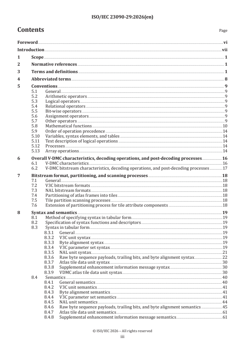
Contents Page
Foreword .vi
Introduction .vii
1 Scope . 1
2 Normative references . 1
3 Terms and definitions . 1
4 Abbreviated terms . 8
5 Conventions . 9
5.1 General .9
5.2 Arithmetic operators .9
5.3 Logical operators .9
5.4 Relational operators .9
5.5 Bit-wise operators .9
5.6 Assignment operators .9
5.7 Other operators .9
5.8 Mathematical functions .10
5.9 Order of operation precedence .14
5.10 Variables, syntax elements, and tables .14
5.11 Text description of logical operations .14
5.12 Processes .14
5.13 Array operations .14
6 Overall V-DMC characteristics, decoding operations, and post-decoding processes .16
6.1 V-DMC characteristics .16
6.2 V-DMC bitstream characteristics, decoding operations, and post-decoding processes .17
7 Bitstream format, partitioning, and scanning processes .18
7.1 General .18
7.2 V3C bitstream formats .18
7.3 NAL bitstream formats .18
7.4 Partitioning of atlas frames into tiles .18
7.5 Tile partition scanning processes .18
7.6 Extension of partitioning process for tile attribute components .18
8 Syntax and semantics . 19
8.1 Method of specifying syntax in tabular form . .19
8.2 Specification of syntax functions and descriptors .19
8.3 Syntax in tabular form .19
8.3.1 General .19
8.3.2 V3C unit syntax .19
8.3.3 Byte alignment syntax .19
8.3.4 V3C parameter set syntax .19
8.3.5 NAL unit syntax . .21
8.3.6 Raw byte sequence payloads, trailing bits, and byte alignment syntax . 22
8.3.7 Atlas tile data unit syntax . 30
8.3.8 Supplemental enhancement information message syntax . 30
8.3.9 VDMC atlas tile data unit syntax . 30
8.4 Semantics . 40
8.4.1 General semantics . 40
8.4.2 V3C unit semantics .41
8.4.3 Byte alignment semantics .41
8.4.4 V3C parameter set semantics .41
8.4.5 NAL unit semantics . 44
8.4.6 Raw byte sequence payloads, trailing bits, and byte alignment semantics .45
8.4.7 Atlas tile data unit semantics .61
8.4.8 Supplemental enhancement information message semantics .61
© ISO/IEC 2026 – All rights reserved
iii
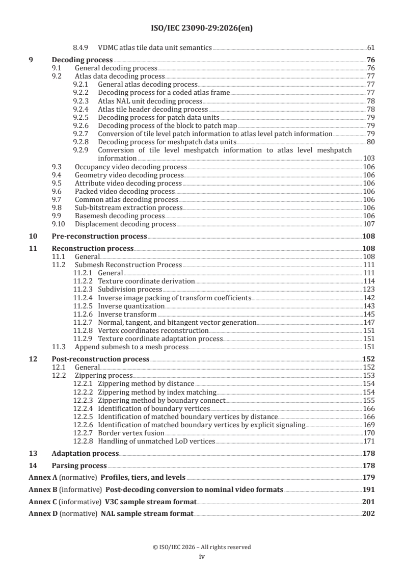
8.4.9 VDMC atlas tile data unit semantics .61
9 Decoding process . 76
9.1 General decoding process .76
9.2 Atlas data decoding process . 77
9.2.1 General atlas decoding process . 77
9.2.2 Decoding process for a coded atlas frame . 77
9.2.3 Atlas NAL unit decoding process . 78
9.2.4 Atlas tile header decoding process . 78
9.2.5 Decoding process for patch data units . 79
9.2.6 Decoding process of the block to patch map . 79
9.2.7 Conversion of tile level patch information to atlas level patch information . 79
9.2.8 Decoding process for meshpatch data units . 80
9.2.9 Conversion of tile level meshpatch information to atlas level meshpatch
information . 103
9.3 Occupancy video decoding process . 106
9.4 Geometry video decoding process . 106
9.5 Attribute video decoding process . 106
9.6 Packed video decoding process . 106
9.7 Common atlas decoding process . 106
9.8 Sub-bitstream extraction process . 106
9.9 Basemesh decoding process . 106
9.10 Displacement decoding process . 107
10 Pre-reconstruction process .108
11 Reconstruction process .108
11.1 General . 108
11.2 Submesh Reconstruction Process . 111
11.2.1 General . 111
11.2.2 Texture coordinate derivation .114
11.2.3 Subdivision process . 123
11.2.4 Inverse image packing of transform coefficients .142
11.2.5 Inverse quantization .143
11.2.6 Inverse transform .145
11.2.7 Normal, tangent, and bitangent vector generation .147
11.2.8 Vertex coordinates reconstruction . 151
11.2.9 Texture coordinate adaptation process . 151
11.3 Append submesh to a mesh process . 151
12 Post-reconstruction process .152
12.1 General . 152
12.2 Zippering process . . 153
12.2.1 Zippering method by distance .154
12.2.2 Zippering method by index matching .154
12.2.3 Zippering method by boundary connect. 155
12.2.4 Identification of boundary vertices . 166
12.2.5 Identification of matched boundary vertices by distance . 166
12.2.6 Identification of matched boundary vertices by explicit signaling . 169
12.2.7 Border vertex fusion .170
12.2.8 Handling of unmatched LoD vertices .171
13 Adaptation process .178
14 Parsing process .178
Annex A (normative) Profiles, tiers, and levels .179
Annex B (informative) Post-decoding conversion to nominal video formats .191
Annex C (informative) V3C sample stream format.201
Annex D (normative) NAL sample stream format .202
© ISO/IEC 2026 – All rights reserved
iv
Annex E (normative) Atlas hypothetical reference decoder .203
Annex F (normative) Supplemental enhancement information . 204
Annex G (informative) Volumetric usability information . 234
Annex H (normative) Basemesh sub-bitstream .236
Annex I (normative) MPEG edgebreaker static mesh coding .327
Annex J (normative) Arithmetic coded displacement sub-bitstream . 402
Annex K (normative) Inverse binarization process . 466
Annex L (normative) MPEG motion coding .477
Bibliography . 484
© ISO/IEC 2026 – All rights reserved
v
Foreword
ISO (the International Organization for Standardization) is a worldwide federation of national standards
bodies (ISO member bodies). The work of preparing International Standards is normally carried out through
ISO technical committees. Each member body interested in a subject for which a technical committee
has been established has the right to be represented on that committee. International organizations,
governmental and non-governmental, in liaison with ISO, also take part in the work. ISO collaborates closely
with the International Electrotechnical Commission (IEC) on all matters of electrotechnical standardization.
The procedures used to develop this document and those intended for its further maintenance are described
in the ISO/IEC Directives, Part 1. In particular, the different approval criteria needed for the different types
of ISO documents should be noted. This document was drafted in accordance with the editorial rules of the
ISO/IEC Directives, Part 2 (see www.iso.org/directives).
Attention is drawn to the possibility that some of the elements of this document may be the subject of patent
rights. ISO shall not be held responsible for identifying any or all such patent rights. Details of any patent
rights identified during the development of the document will be in the Introduction and/or on the ISO list of
patent declarations received (see www.iso.org/patents).
Any trade name used in this document is information given for the convenience of users and does not
constitute an endorsement.
For an explanation of the voluntary nature of standards, the meaning of ISO specific terms and expressions
related to conformity assessment, as well as information about ISO's adherence to the World Trade
Organization (WTO) principles in the Technical Barriers to Trade (TBT), see www.iso.org/iso/foreword.html.
This document was prepared by Joint Technical Committee ISO/IEC JTC 1, Information technology,
Subcommittee SC 29, Coding of audio, picture, multimedia and hypermedia information.
A list of all parts in the ISO/IEC 23090 series can be found on the ISO website.
Any feedback or questions on this document should be directed to the user’s national standards
body. A complete listing of these bodies can be found at www.iso.org/members.html and
www.iec.ch/national-committees.
© ISO/IEC 2026 – All rights reserved
vi
Introduction
The advances in 3D capture, modelling, and rendering have promoted the ubiquitous presence of 3D content
across several platforms and devices.
3D meshes, along with point clouds and immersive video, are widely used to represent such immersive
content. A mesh is composed of several polygons that describe the boundary surface of a volumetric object.
Each polygon is defined by its vertices in 3D space and the information on how the vertices are connected,
referred to as connectivity information. Optionally, vertex attributes, such as colours, normal, etc., can
be associated with the mesh vertices. Attributes can also be associated with the surface of the mesh by
exploiting mapping information that describes a parameterization of the mesh onto 2D regions of the
plane. Such mapping is usually described by a set of parametric coordinates, referred to as UV coordinates
or texture coordinates. 2D attribute maps are used to store high resolution attribute information such as
texture, normal, material ID etc. Such information can be used for various purposes such as texture mapping
and shading.
To achieve a realistic representation of an object or scene, 3D meshes are becoming increasingly
sophisticated, and a significant amount of data is generated for the creation and consumption of those
meshes. When uncompressed, these data can be costly in terms of storage and transmission. Furthermore,
dynamic mesh sequences may require even larger amounts of data, since it may consist of a significant
quantity of information changing over time. A visual volumetric video-based coding (V3C) standard has been
created to support the distribution of volumetric data, currently addressing point clouds (ISO/IEC 23090-5)
and immersive video content (ISO/IEC 23090-12). Therefore, this document was developed to support
compression of 3D video-based mesh coding utilizing the ISO/IEC V3C standard (ISO/IEC 23090-5).
© ISO/IEC 2026 – All rights reserved
vii
International Standard ISO/IEC 23090-29:2026(en)
Information technology — Coded representation of
immersive media —
Part 29:
Video-based dynamic mesh coding (V-DMC)
1 Scope
This document specifies syntax, semantics, and decoding for video based dynamic mesh coding (V-DMC),
basemesh coding, MPEG edgebreaker static mesh coding, and arithmetic coded displacement. Furthermore,
this document specifies processes that can be used for reconstruction of visual volumetric media and also
include additional processes such as post-decoding, pre-reconstruction, post-reconstruction, and adaptation.
2 Normative references
The following documents are referred to in the text in such a way that some or all of their content constitutes
requirements of this document. For dated references, only the edition cited applies. For undated references,
the latest edition of the referenced document (including any amendments) applies.
ISO /IEC 23090-5:2026, Information technology — Coded Representation of Immersive Media — Part 5: Visual
volumetric video-based coding (V3C) and video-based point cloud compression (V-PCC)
3 Terms and definitions
For the purposes of this document, the terms and definitions given in ISO/IEC 23090-5 and the following
apply.
ISO and IEC maintain terminology databases for use in standardization at the following addresses:
— ISO Online browsing platform: available at https:// www .iso .org/ obp
— IEC Electropedia: available at https:// www .electropedia .org/
3.1
atlas
collection of 2D bounding boxes and their associated information placed onto a rectangular frame
and corresponding to a volume in 3D space on which volumetric data is rendered and a list of metadata
corresponding to a part of a surface of a mesh in 3D space
3.2
atlas frame
2D rectangular array of atlas samples onto which patches are projected and additional information related to
the patches, corresponding to a volumetric frame and a list of meshpatches (3.8) and additional information
related to the meshpatches (3.8), corresponding to a volumetric frame
3.3
atlas sample
position on the rectangular frame onto which patches that are associated with an atlas (3.1) are projected or
element of a list of meshpatches (3.8) that are associated with an atlas (3.1)
© ISO/IEC 2026 – All rights reserved
3.4
attribute frame
2D rectangular array created through the aggregation of patches and meshpatches (3.8) containing values of
a specific attribute
3.5
attribute map
image for mapping an attribute into a surface of 3D shape
3.6
basemesh frame
array of submeshes (3.12) associated with each meshpatch (3.8) corresponding to a volumetric frame
3.7
geometry frame
2D array created through the aggregation of the geometry information associated with each patch and
meshpatch (3.8)
3.8
meshpatch
element of an atlas (3.1) associated with basemesh information
3.9
meshpatch data
data in an atlas (3.1) associated with a meshpatch (3.8) that enables the conversion of basemesh into the
reconstructed mesh
3.10
orthoAtlas
orthographic projection and packing of the faces into a texture atlas
3.11
subdivision
process of dividing the mesh faces into a number of sub-faces
3.12
submesh
independently decodable region of a basemesh
3.13
subpatch
set of parameters in the meshpatch (3.8) to construct a homography transform used to map the vertex
coordinates of a mesh surface associated with a given faceId to a set of UV texture coordinates and their
connectivity indices
3.14
texture mapping
process of transferring attributes from a 2D attribute (texture) map into surface of a 3D mesh
3.15
atlas tile
independently decodable rectangular region of atlas frame (3.2), consisting of a geometry tile (3.16), an
attribute tile (3.17), or both, with no dependencies on other atlas tiles in the current frame
3.16
geometry tile
independently decodable rectangular region within an atlas tile (3.15) that is associated with a geometry
frame (3.7)
© ISO/IEC 2026 – All rights reserved
3.17
attribute tile
independently decodable rectangular region within an atlas tile (3.15) that is associated with an attribute
frame (3.4)
3.18
basemesh layer set
set of layers represented within a bitstream created from another bitstream by operation of the basemeshsub-
bitstream extraction process (3.19) with another bitstream, and the target highest BmTemporalId equal to 6
as inputs
3.19
basemesh sub-bitstream extraction process
specified process by which basemesh NAL units in a bitstream that do not belong to a target set, determined
by a target highest BmTemporalId tBmIdTarget, are removed from the bitstream, with the output sub-
bitstream consisting of the basemesh NAL units in the bitstream that belong to the target set. This process
removes all NAL units with BmTemporalId greater than tBmIdTarget
3.20
basemesh sub-layer
temporal basemesh sub-layer
temporal scalable layer of a temporal scalable basemesh sub-bitstream, consisting of BMCL NAL units with a
particular value of the BmTemporalId variable and the associated non-BMCL NAL units
3.21
coded basemesh
coded basemesh frame
coded representation of a basemesh frame
3.22
coded basemesh access unit
set of basemesh NAL units that are associated with each other according to a specified classification rule,
are consecutive in decoding order, and contain all basemesh NAL units pertaining to one particular output
time
3.23
decoded basemesh
decoded basemesh frame
basemesh derived by decoding a coded basemesh (3.21)
3.24
motion decoder
process used for inter basemesh decoding
3.25
motion sub-bitstream
sequence of bits extracted from V3C bitstream that contains specified syntax that represents motion of a
basemesh
3.26
operation point
bitstream created from another bitstream by operation of the basemeshsub-bitstream extraction process
(3.29) with another bitstream, and a target highest BmTemporalId as inputs
3.27
pruned decoded basemesh
result of pruning a decoded basemesh (3.23) by removing member from the struct decoded basemesh (3.23)
that are not specified at the decoding output
© ISO/IEC 2026 – All rights reserved
3.28
sub-layer non-reference basemesh frame
SLNR basemesh frame
basemesh frame (3.6) that cannot be used for inter prediction in the decoding process of subsequent
basemesh frames of the same basemesh sub-layer (3.20) in decoding order
Note 1 to entry: An SLNR basemesh frame can be used for inter prediction in the decoding process of subsequent
basemesh frames of higher basemesh sub-layers in decoding order.
3.29
sub-layer reference basemesh frame
basemesh frame (3.6) that may be used for inter prediction in the decoding process of subsequent basemesh
frames of the same basemesh sub-layer (3.20) in decoding order
Note 1 to entry: A sub-layer reference basemesh frame can also be used for inter prediction in the decoding process of
subsequent basemesh frames of higher basemesh sub-layers in decoding order.
3.30
sub-layer representation
subset of the bitstream consisting of basemesh NAL units of a particular basemesh sub-layer (3.20) and the
lower basemesh sub-layers
3.31
step-wise temporal sub-layer access basemesh/STSA basemesh
coded basemesh for which each BMCL NAL unit has bmesh_nal_unit_type equal to STSA_R or STSA_N
Note 1 to entry: An STSA basemesh does not use basemeshes with the same BmTemporalId as the STSA basemesh for
inter prediction reference. Basemeshes following an STSA basemesh in decoding order with the same BmTemporalId as
the STSA basemesh do not use basemeshes prior to the STSA basemesh in decoding order with the same BmTemporalId
as the STSA basemesh for inter prediction reference. An STSA basemesh enables up-switching, at the STSA basemesh,
to the basemesh sub-layer containing the STSA basemesh, from the immediately lower basemesh sub-layer. STSA
basemeshes have BmTemporalId greater than 0.
3.32
temporal sub-layer access unit/TSA access unit
access unit in which the coded basemesh (3.21) with bmesh_nal_layer_id equal to 0 is a TSA basemesh
3.33
temporal sub-layer access basemesh/TSA basemesh
coded basemesh for which each BMCL NAL unit has bmesh_nal_unit_type equal to TSA_R or TSA_N
Note 1 to entry: A TSA basemesh and basemeshes following the TSA basemesh in decoding order do not use basemeshes
prior to the TSA basemesh in decoding order with BmTemporalId greater than or equal to that of the TSA basemesh
for inter prediction reference. A TSA basemesh enables up-switching, at the TSA basemesh, to the sub-layer containing
the TSA basemesh or any higher sub-layer, from the immediately lower sub-layer. TSA basemeshes have BmTemporalId
greater than 0.
3.34
attribute array
attribute table
collection of attribute values accessible with a unique index associated with each attribute vertex
3.35
attribute seam
boundary edge (3.39) associated with the auxiliary connectivity (3.37) that is not a boundary edge (3.39) on
the primary connectivity (3.58)
3.36
auxiliary attribute
set of values attached to either each attribute vertex, or each face of the mesh (3.54), accessed by an index in
an attribute table (3.34)
© ISO/IEC 2026 – All rights reserved
3.37
auxiliary connectivity
connectivity (3.42) associated with the auxiliary attribute (3.36), which can be identical to the primary
connectivity (3.58)
3.38
boundary
closed loop connecting boundary edges (3.39)
3.39
boundary edge
edge incident to only one face
3.40
CLERS
set of symbols used to encode the primary connectivity (3.58)
3.41
connected component
maximal connected subgraph of the connectivity (3.42)
3.42
connectivity
graph defining face to vertex incidence
3.43
corner
incidence of a vertex and a face
3.44
corner table
table representing the connectivity (3.42) by associating each corner (3.43) to both a vertex and an opposite
corner (3.43), where boundary edges (3.39) are signaled by negative opposite corner (3.43) values
3.45
degenerate face
face that dereferences to the same index in an attribute table (3.34) for at least two of its corners (3.43)
3.46
external boundary
first boundary (3.38) in a connected component (3.41) traversed when encoding its connectivity (3.42)
3.47
fan
set of connected faces that share a unique central vertex, where each face in the set shares at least one edge
with another face in the set when the fan consists of more than one face, and where each edge is shared by
at most two faces
3.48
handle
topological feature distinguishing a torus from a sphere, where the number of such topological features in a
manifold mesh (3.53) with boundaries (3.38) is identified by the Euler-Poincaré characteristic
3.49
handle table
table containing a list of pairs of values representing opposite corners as hints for the reconstruction of the
correct surface connectivity (3.42) with handles (3.48) or internal boundaries (3.51) during decoding
3.50
indexed face set
structure containing attribute arrays (3.34), and arrays associating each corner of the mesh with an index
dereferencing those for each of the primary attribute (3.57) and the auxiliary attributes (3.36)
© ISO/IEC 2026 – All rights reserved
3.51
internal boundary
boundary (3.38) attached to a connected component (3.41) with more than one boundary (3.38), and which is
not the external boundary (3.46) of this connected component (3.41)
3.52
isolated vertices
vertex that is not connected to any other vertex
3.53
manifold mesh
mesh (3.54) for which each edge is incident to only one or two faces, and the set of faces incident to a vertex
form a closed or an open fan (3.47)
3.54
mesh
collection of faces that are connected by their per attribute common edges and vertices, with a per attribute
cyclic order of corners (3.43) that defines the per-attribute orientation associated with each face
3.55
orientable manifold mesh
manifold mesh (3.53) in which for all per vertex attributes any two adjacent faces have compatible orientation,
if the two vertices of the common edge are in opposite order in the cyclic order of each respective face
3.56
orientable manifold mesh with boundaries
orientable manifold mesh (3.55) that has one or more boundaries (3.38)
3.57
primary attribute
first set of values attached to each vertex of a mesh (3.54), accessed by an index in an attribute table (3.36)
3.58
primary connectivity
connectivity (3.42) associated with the primary attribute (3.57)
3.59
triangular mesh
mesh (3.54) where faces correspond to triangles
3.60
subdisplacement
independently decodable displacement (3.8) data associated with a submesh (3.12)
3.61
coded basemesh sequence
CBMS
sequence of coded basemesh access units (3.22), in decoding order, of an IRAP coded basemesh access unit
(3.62) with NoBmOutputBeforeRecoveryFlag equal to 1, followed by zero or more coded basemesh access
units (3.22) that are not IRAP coded basemesh access units (3.62) with NoBmOutputBeforeRecoveryFlag
equal to 1, including all subsequent coded basemesh access units (3.22) up to but not including any
subsequent coded basemesh access unit (3.22) that is an IRAP coded basemesh access unit (3.62) with
NoBmOutputBeforeRecoveryFlag equal to 1
3.62
intra random access point coded basemesh access unit
IRAP coded basemesh access unit
access unit in which the coded basemesh (3.21) with bmesh_nal_layer_id equal to 0 is an IRAP coded basemesh
frame (3.63)
© ISO/IEC 2026 – All rights reserved
3.63
intra random access point coded basemesh frame
IRAP coded basemesh frame
coded basemesh (3.21) for which each BMCL NAL unit (3.66) has bmesh_nal_unit_type in the range of BNAL_
BLA_W_LP to BNAL_RSV_IRAP_BMCL_23, inclusive
3.64
basemesh NAL unit
BNAL unit
syntax structure within a basemesh bitstream containing an indication of the type of data to follow and
bytes containing that data in the form of an RBSP
3.65
coded submesh NAL unit
basemesh NAL unit (3.64) that has bmesh_nal_unit_type in the range of BNAL_TRAIL_N to BNAL_SKIP_R,
inclusive, or in the range of BNAL_BLA_W_LP to BNAL_RSV_IRAP_BMCL_23, inclusive, which indicates that
the basemesh NAL unit (3.64) contains a coded submesh (3.12)
3.66
basemesh coding layer NAL unit
BMCL NAL unit
collective term for coded submesh NAL units (3.65) and the subset of basemesh NAL units (3.64) that have
reserved values of bmesh_nal_unit_type that are classified as BMCL NAL units
3.67
non-BMCL NAL unit
basemesh NAL unit (3.64) that is not an BMCL NAL unit (3.66)
3.68
coded displacement sequence
CDS
sequence of coded displacement access units (3.71), in decoding order, of an IRAP coded displacement access unit
(3.69) with NoDisplOutputBeforeRecoveryFlag equal to 1, followed by zero or more coded displacement access
units (3.71) that are not IRAP coded displacement access units (3.69) with NoDisplOutputBeforeRecoveryFlag
equal to 1, including all subsequent coded displacement access units (3.71) up to but not including any
subsequent coded displacement access unit (3.71) that is an IRAP coded displacement access unit (3.69) with
NoDisplOutputBeforeRecoveryFlag equal to 1
3.69
intra random access point coded displacement access unit
IRAP coded displacement access unit
access unit in which the coded displacement with displ_nal_layer_id equal to 0 is an IRAP coded displacement
frame (3.70)
3.70
intra random access point coded displacement frame
IRAP coded displacement frame
coded displacement for which each DCL NAL unit (3.76) has displ_nal_unit_type in the range of DNAL_
BLA_W_LP to DNAL_RSV_IRAP_DCL_23, inclusive
3.71
coded displacement access unit
set of displacement NAL units (3.74) that are associated with each other according to a specified classification
rule, are consecutive in decoding order, and contain all displacement NAL units (3.74) pertaining to one
particular output time
3.72
coded displacement
coded displacement frame
coded representation of a displacement frame (3.73)
© ISO/IEC 2026 – All rights reserved
3.73
displacement frame
array of subdisplacements (3.60) associated with each meshpatch (3.8) corresponding to a volumetric frame
3.74
displacement NAL unit
DNAL unit
syntax structure within a displacement bitstream containing an indication of the type of data to follow and
bytes containing that data in the form of an RBSP
3.75
coded subdisplacement NAL unit
displacement NAL unit (3.74) that has displ_nal_unit_type in the range of DNAL_TRAIL_N to DNAL_SKIP_R,
inclusive, or in the range of DNAL_BLA_W_LP to DNAL_RSV_IRAP_DCL_23, inclusive, which indicates that
the displacement NAL unit (3.74) contains a coded subdisplacement (3.60)
3.76
displacement coding layer NAL unit
DCL NAL unit
collective term for coded subdisplacement NAL units (3.75) and the subset of displacement NAL units (3.74)
that have reserved values of displ_nal_unit_type that are classified as DCL NAL units
3.77
non-DCL NAL unit
displacement NAL unit (3.74) that is not an DCL NAL unit (3.76)
4 Abbreviated terms
The following abbreviations apply in addition to the abbreviations in ISO/IEC 23090-5:2026, Clause 4.
BMD basemesh data
CPM contextual probability model
LoD level of detail
V-DMC video-based dynamic mesh coding
BLA broken link access
BMCL basemesh coding layer
BMFPS basemesh frame parameter set
...