

ISO 19697:2026
(Main)Ships and marine technology — Navigation and ship operations — Electronic inclinometers
- Abstract
This document specifies the performance requirements, methods of testing and test results of electronic inclinometers required by the performance standard, IMO resolution MSC.363 (92), in addition to the general requirements contained in IMO Resolution A.694 (17). This document does not apply to the electronic inclinometers installed for purposes which are outside the scope of this document, e.g. monitoring of cargo status.
- Status
- Published
- Publication Date
- 30-Jun-2026
- Technical Committee
- ISO/TC 8/SC 6 - Navigation and ship operations
- Drafting Committee
- ISO/TC 8/SC 6 - Navigation and ship operations
- Current Stage
- 6060 - International Standard published
- Start Date
- 01-Jul-2026
- Due Date
- 30-Apr-2026
- Completion Date
- 01-Jul-2026

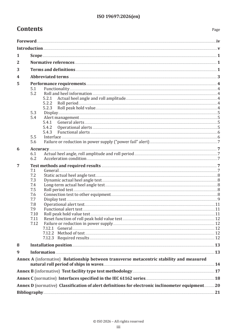
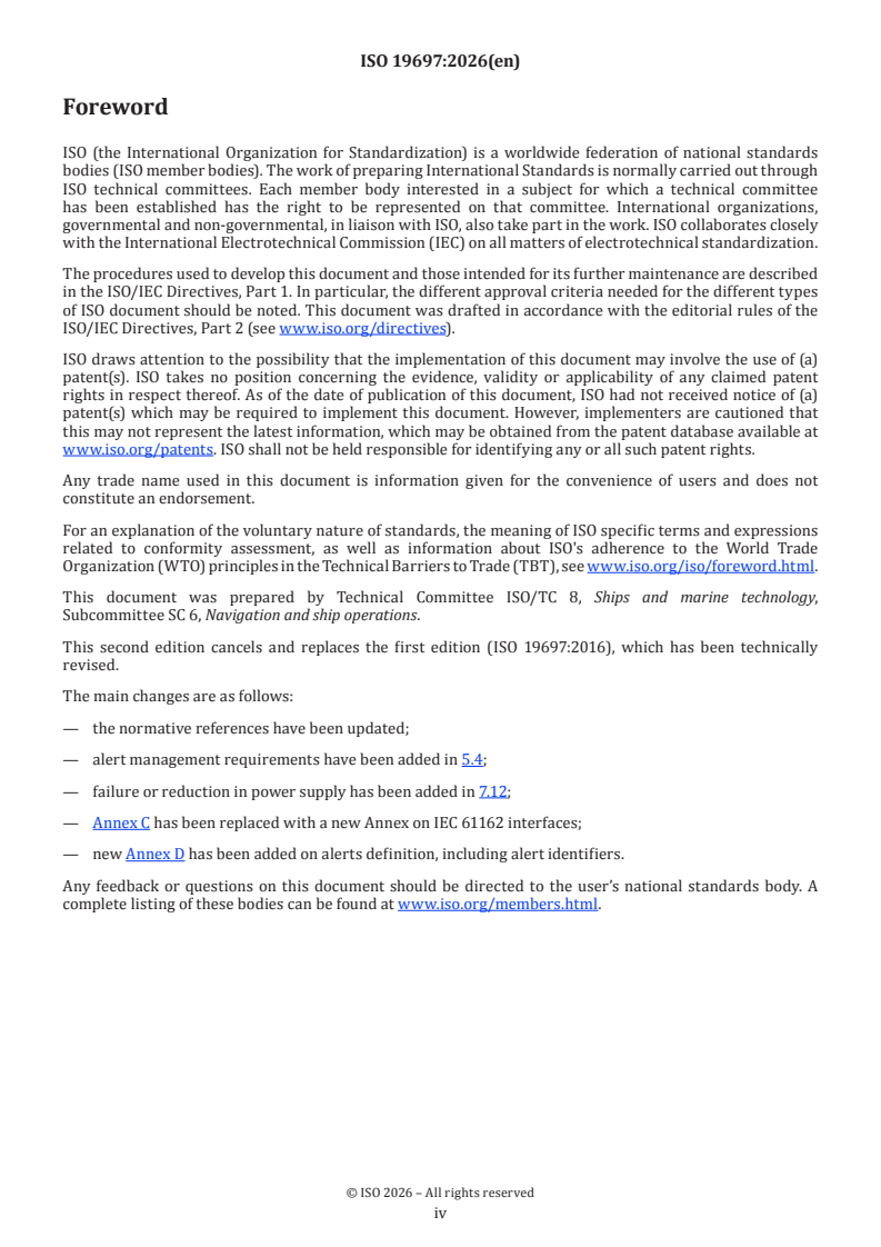
ISO 19697:2026 is an International Standard from ISO for electronic inclinometers used in ships and marine technology. It specifies performance requirements, test methods and required test results for equipment intended to support shipboard decision-making, including roll, heel angle and roll period information. The standard applies to electronic inclinometers covered by IMO resolution MSC.363(92) and the general requirements in IMO resolution A.694(17).
What does ISO 19697:2026 specify?
ISO 19697:2026 specifies how an electronic inclinometer is expected to perform, how it is tested, and what results are required. It also sets the limits for display, alert handling, interfaces and power-failure behaviour so users can judge whether a device fits bridge use and voyage data recorder integration.
The document is organized into clauses on scope, normative references, terms and definitions, abbreviated terms, performance requirements, accuracy, test methods and required results, installation position and information. It then adds four annexes that cover ship-stability context, a test facility method, IEC 61162 interfaces and alert classification.
| Annex | What it covers |
|---|---|
| Annex A | Relationship between transverse metacentric stability and measured natural roll period of ships in waves |
| Annex B | Test facility type test methodology |
| Annex C | Interfaces specified in the IEC 61162 series |
| Annex D | Classification of alert definitions for electronic inclinometer equipment |
What are the key requirements of ISO 19697:2026?
ISO 19697:2026 focuses on reliable measurement, bridge presentation, alerting and system interfacing. For a buyer or engineer, the main question is whether the inclinometer can provide usable heel and roll information, communicate it correctly, and behave predictably during failure or abnormal conditions.
Main functional requirements
Clause 5.1 requires the electronic inclinometer to determine actual heel angle, roll amplitude and roll period with the required accuracy, present the information on a bridge display, and provide a standardized interface for instantaneous heel angle to the voyage data recorder (VDR). In practice, this means the instrument is not just a sensor - it must be usable on the bridge and able to feed other ship systems.
Clause 5.2 extends the measurement range for actual heel angle and roll amplitude to ± 90°, and roll period from 4 s to 40 s. Clause 5.2.3 allows optional roll peak hold value recording and requires a manual single-action reset if that function is provided. That matters for operators who need to see the most recent maximum roll values and clear them cleanly after an event.
Display requirements
Clause 5.3 requires actual heel angle to be shown in analogue form between ± 45°, with the indication allowed to stay at 45° beyond that limit. Roll amplitude must be shown for both sides with at least 1° resolution, and roll period with at least 1 s resolution. If the display is on the bridge, it also has to comply with the shipborne display requirements in IEC 62288 and the related IMO presentation rules.
For users, this means the display must be readable and consistent with bridge practice. Clause 5.3 also allows the display to be dedicated or integrated into other bridge systems.
Alert management
Clause 5.4 requires alert handling to align with bridge alert management requirements. General alert presentation, handling and communication must comply with IMO Resolution MSC.302(87), IEC 62923-1:2018, IEC 62923-2 and the alert definitions in Annex D.
Clause 5.4.2 allows an operational warning when a set heel angle threshold is exceeded. It requires a manual threshold-setting method, acknowledgement, rectification of the alert state, and automatic rectification after the heel angle has remained below the limit for a defined period. In practice, this means the device must not only warn - it must manage the alert state in a way bridge teams can act on.
Clause 5.4.3 requires functional alerts when the inclinometer malfunctions or when heel-angle data are invalid. The device must check its own operability and indicate whether its output is valid. This matters because invalid data can be worse than no data during manoeuvring or casualty response.
Interface and power requirements
Clause 5.5 requires a digital interface for actual heel angle data to other systems such as the VDR, with an update rate of at least 5 Hz. It also requires a digital interface for the displayed roll period and roll amplitude information. The interface has to comply with IEC 61162-2 or IEC 61162-450, and Annex C defines the sentences and logical interfaces used.
Clause 5.6 requires power from the ship’s main source of electrical energy, with operation also possible from the emergency source. If the equipment can keep running after one supply fails, it must raise a power-fail caution while maintaining operation. If power is totally lost, it must provide a status signal so external equipment can raise the appropriate alert.
Accuracy and test performance
Clause 6 requires minimum accuracy of 5 % of reading or ± 1° for angle measurements, whichever is greater, and 5 % of reading or ± 1 s for time measurements, whichever is greater. Clause 6.2 also says the measurement accuracy must not be unduly affected by ship motions such as surging, swaying, heaving, pitching and yawing, or by transverse acceleration from −0.8 g to +0.8 g.
For purchasers and test labs, this is the core performance yardstick. It defines whether a unit remains credible when the ship is moving, not just when it is level in a workshop.
Testing, installation and documentation
Clause 7 defines the required tests for static and dynamic heel angle, long-term drift, roll period, connection to other equipment, display, operational alerts, functional alerts, roll peak hold value, reset and power-supply failure. Clause 8 requires the sensor installation position to be recorded and made available for VDR configuration. Clause 9 requires adequate equipment documentation so crew members can operate and maintain the equipment efficiently.
What terms does ISO 19697:2026 define?
ISO 19697:2026 defines the key terms that frame how the equipment and its tests are described.
- Electronic inclinometer - an electronic device that provides roll period, roll amplitude and heel angle information for the ship.
- Actual heel angle - the momentary roll angle referenced to a levelled ship on the port or starboard side.
- Roll amplitude - the maximum heel angle values to port or starboard.
- Roll period - the time between two successive maximum heel values on the same side of the ship.
- Roll peak hold value - the maximum roll amplitude values recorded since the last reset.
- Bridge alert management (BAM) - the overall concept for managing and presenting alerts on the bridge.
- Central alert management (CAM) - the functionality for managing alerts and their communication between the CAM-HMI and ship systems.
- Equipment under test (EUT) - the electronic inclinometer system being tested.
Who uses ISO 19697:2026?
ISO 19697:2026 is used by manufacturers of electronic inclinometers, bridge-system integrators, test laboratories and ship operators. It is relevant when specifying, designing, verifying or purchasing equipment that must provide heel and roll information on the bridge and to other ship systems.
It is also used by installation and maintenance personnel, because the standard addresses sensor placement, interface behaviour and documentation needed for operation and upkeep. Crew members who rely on the equipment for navigation and stability awareness are also part of the intended audience.
What changed in ISO 19697:2026 from the previous edition?
ISO 19697:2026 is the second edition and cancels and replaces ISO 19697:2016. The standard states that it has been technically revised.
The main changes listed are updated normative references, added alert management requirements in 5.4, added failure or reduction in power supply requirements in 7.12, replacement of Annex C with a new annex on IEC 61162 interfaces, and addition of Annex D on alert definitions including alert identifiers.
Which standards are used with ISO 19697:2026?
ISO 19697:2026 refers to several external documents that contribute to interfaces, displays, alerts and bridge presentation.
- IEC 61162-1 - provides the sentence format used for text transmission and bridge-related data messages.
- IEC 61162-2 - supports the required digital interface for transmitting inclinometer data.
- IEC 61162-450 - provides the Ethernet-based digital interface option.
- IEC 62288 - sets the presentation requirements, test methods and results for navigation-related information on shipborne displays.
- IEC 62923-1:2018 - provides bridge alert management operational and performance requirements and test methods.
- IEC 62923-2:2018 - provides alert and cluster identifiers and additional alert features.
- IMO Resolution MSC.302(87) - gives the performance standards for bridge alert management.
- IMO Resolution MSC.466(101) - amends the shipborne display presentation standard referenced by the document.
What does the ISO 19697:2026 document contain?
ISO 19697:2026 contains performance requirements, test procedures and required results for a shipboard electronic inclinometer. It also includes practical test arrangements for static and dynamic motion, long-duration checking, roll-period measurement, display behaviour, alert behaviour and power-loss behaviour.
The annexes add useful context and implementation detail. Annex A explains why measured natural roll period can relate to transverse metacentric stability. Annex B describes an inverted-pendulum style test facility. Annex C lists the IEC 61162 sentences and closed-contact signal used for VDR, CAM and alert communication. Annex D gives the alert identifiers and classifications used for electronic inclinometer equipment.
The document also includes example display figures and an interface figure, which help readers understand the intended bridge presentation and logical connections without prescribing a single display design.
Relations
- Effective Date
- 08-Oct-2022
Get Certified
Connect with accredited certification bodies for this standard

DNV
DNV is an independent assurance and risk management provider.

Lloyd's Register
Lloyd's Register is a global professional services organisation specialising in engineering and technology.

FSC International
Forest Stewardship Council certification.
Sponsored listings
Frequently Asked Questions
ISO 19697:2026 is a standard published by the International Organization for Standardization (ISO). Its full title is "Ships and marine technology — Navigation and ship operations — Electronic inclinometers". This standard covers: This document specifies the performance requirements, methods of testing and test results of electronic inclinometers required by the performance standard, IMO resolution MSC.363 (92), in addition to the general requirements contained in IMO Resolution A.694 (17). This document does not apply to the electronic inclinometers installed for purposes which are outside the scope of this document, e.g. monitoring of cargo status.
This document specifies the performance requirements, methods of testing and test results of electronic inclinometers required by the performance standard, IMO resolution MSC.363 (92), in addition to the general requirements contained in IMO Resolution A.694 (17). This document does not apply to the electronic inclinometers installed for purposes which are outside the scope of this document, e.g. monitoring of cargo status.
ISO 19697:2026 is classified under the following ICS (International Classification for Standards) categories: 47.020.70 - Navigation and control equipment. The ICS classification helps identify the subject area and facilitates finding related standards.
ISO 19697:2026 has the following relationships with other standards: It is inter standard links to ISO 19697:2016. Understanding these relationships helps ensure you are using the most current and applicable version of the standard.
ISO 19697:2026 is available in PDF format for immediate download after purchase. The document can be added to your cart and obtained through the secure checkout process. Digital delivery ensures instant access to the complete standard document.
Standards Content (Sample)
International
Standard
ISO 19697
Second edition
Ships and marine technology —
2026-07
Navigation and ship operations —
Electronic inclinometers
Navires et technologie maritime — Navigation et opérations
maritimes — Inclinomètres électroniques
Reference number
© ISO 2026
All rights reserved. Unless otherwise specified, or required in the context of its implementation, no part of this publication may
be reproduced or utilized otherwise in any form or by any means, electronic or mechanical, including photocopying, or posting on
the internet or an intranet, without prior written permission. Permission can be requested from either ISO at the address below
or ISO’s member body in the country of the requester.
ISO copyright office
CP 401 • Ch. de Blandonnet 8
CH-1214 Vernier, Geneva
Phone: +41 22 749 01 11
Email: copyright@iso.org
Website: www.iso.org
Published in Switzerland
ii
Contents Page
Foreword .iv
Introduction .v
1 Scope . 1
2 Normative references . 1
3 Terms and definitions . 1
4 Abbreviated terms . 3
5 Performance requirements . . 4
5.1 Functionality .4
5.2 Roll and heel information .4
5.2.1 Actual heel angle and roll amplitude.4
5.2.2 Roll period .4
5.2.3 Roll peak hold value . .4
5.3 Display.5
5.4 Alert management .5
5.4.1 General alerts .5
5.4.2 Operational alerts .5
5.4.3 Functional alerts .6
5.5 Interface .6
5.6 Failure or reduction in power supply (“power fail” alert) .7
6 Accuracy . 7
6.1 Actual heel angle, roll amplitude and roll period .7
6.2 Acceleration condition .7
7 Test methods and required results . 7
7.1 General .7
7.2 Static actual heel angle test .8
7.3 Dynamic actual heel angle test .8
7.4 Long-term actual heel angle test .8
7.5 Roll period test .8
7.6 Connection test to other equipment .8
7.7 Display test .9
7.8 Operational alert test.11
7.9 Functional alert test .11
7.10 Roll peak hold value test .11
7.11 Reset function of roll peak hold value test . 12
7.12 Failure or reduction in power supply . 12
7.12.1 General . 12
7.12.2 Method of test . 12
7.12.3 Required results . 12
8 Installation position . .13
9 Information .13
Annex A (informative) Relationship between transverse metacentric stability and measured
natural roll period of ships in waves . 14
Annex B (informative) Test facility type test methodology . 17
Annex C (normative) Interfaces specified in the IEC 61162 series .18
Annex D (normative) Classification of alert definitions for electronic inclinometer equipment .20
Bibliography .21
iii
Foreword
ISO (the International Organization for Standardization) is a worldwide federation of national standards
bodies (ISO member bodies). The work of preparing International Standards is normally carried out through
ISO technical committees. Each member body interested in a subject for which a technical committee
has been established has the right to be represented on that committee. International organizations,
governmental and non-governmental, in liaison with ISO, also take part in the work. ISO collaborates closely
with the International Electrotechnical Commission (IEC) on all matters of electrotechnical standardization.
The procedures used to develop this document and those intended for its further maintenance are described
in the ISO/IEC Directives, Part 1. In particular, the different approval criteria needed for the different types
of ISO document should be noted. This document was drafted in accordance with the editorial rules of the
ISO/IEC Directives, Part 2 (see www.iso.org/directives).
ISO draws attention to the possibility that the implementation of this document may involve the use of (a)
patent(s). ISO takes no position concerning the evidence, validity or applicability of any claimed patent
rights in respect thereof. As of the date of publication of this document, ISO had not received notice of (a)
patent(s) which may be required to implement this document. However, implementers are cautioned that
this may not represent the latest information, which may be obtained from the patent database available at
www.iso.org/patents. ISO shall not be held responsible for identifying any or all such patent rights.
Any trade name used in this document is information given for the convenience of users and does not
constitute an endorsement.
For an explanation of the voluntary nature of standards, the meaning of ISO specific terms and expressions
related to conformity assessment, as well as information about ISO's adherence to the World Trade
Organization (WTO) principles in the Technical Barriers to Trade (TBT), see www.iso.org/iso/foreword.html.
This document was prepared by Technical Committee ISO/TC 8, Ships and marine technology,
Subcommittee SC 6, Navigation and ship operations.
This second edition cancels and replaces the first edition (ISO 19697:2016), which has been technically
revised.
The main changes are as follows:
— the normative references have been updated;
— alert management requirements have been added in 5.4;
— failure or reduction in power supply has been added in 7.12;
— Annex C has been replaced with a new Annex on IEC 61162 interfaces;
— new Annex D has been added on alerts definition, including alert identifiers.
Any feedback or questions on this document should be directed to the user’s national standards body. A
complete listing of these bodies can be found at www.iso.org/members.html.
iv
Introduction
In accordance with IMO Resolution MSC.363 (92), Article 2.1, electronic inclinometers are intended to support
the decision-making process on board in order to avoid dangerous situations, as well as assist in and facilitate
maritime casualty investigation. The requirements in this document take into account human factors,
ergonomic principles and advances in technology. The electronic inclinometers are mainly composed of a set
of sensors, a signal processor, a display, an input device and an interface to other systems.
Electronic inclinometers provide information about:
— actual heel angle;
— roll amplitude;
— roll period;
— stability.
Any text in this document which is a citation from the IMO Resolution MSC.363 (92) appears in italics.
Within these citations, any changes to the original wording of the IMO Resolution MSC.363 (92), are written
in upright font.
NOTE The relationship between ship stability and the measured natural frequency of roll motion using an
electronic inclinometer is explained in Annex A.
v
International Standard ISO 19697:2026(en)
Ships and marine technology — Navigation and ship
operations — Electronic inclinometers
1 Scope
This document specifies the performance requirements, methods of testing and test results of electronic
inclinometers required by the performance standard, IMO resolution MSC.363 (92), in addition to the
general requirements contained in IMO Resolution A.694 (17).
This document does not apply to the electronic inclinometers installed for purposes which are outside the
scope of this document, e.g. monitoring of cargo status.
2 Normative references
The following documents are referred to in the text in such a way that some or all of their content constitutes
requirements of this document. For dated references, only the edition cited applies. For undated references,
the latest edition of the referenced document (including any amendments) applies.
IEC 61162-1, Maritime navigation and radiocommunication equipment and systems — Digital interfaces — Part
1: Single talker and multiple listeners
IEC 61162-2, Maritime navigation and radiocommunication equipment and systems — Digital interfaces —
Part 2: Single talker and multiple listeners, high-speed transmission
IEC 61162-450, Maritime navigation and radiocommunication equipment and systems — Digital interfaces —
Part 450: Multiple talkers and multiple listeners — Ethernet interconnection
IEC 62288, Maritime navigation and radiocommunication equipment and systems — Presentation of navigation-
related information on shipborne navigational displays — General requirements, methods of testing and required
test results
IEC 62923-1:2018, Maritime navigation and radiocommunication equipment and systems — Bridge alert
management — Part 1: Operational and performance requirements, methods of testing and required test results
IEC 62923-2:2018, Maritime navigation and radiocommunication equipment and systems — Bridge alert
management — Part 2: Alert and cluster identifiers and other additional features
IMO Resolution MSC.302(87), Performance standards for bridge alert management
IMO Resolution MSC.466(101), Amendments to the performance standards for the presentation of
navigationrelated information on shipborne navigational displays (Resolution MSC.191(79))
3 Terms and definitions
For the purposes of this document, the following terms and definitions apply.
ISO and IEC maintain terminology databases for use in standardization at the following addresses:
— ISO Online browsing platform: available at https:// www .iso .org/ obp
— IEC Electropedia: available at https:// www .electropedia .org/
3.1
electronic inclinometer
electronic device that provides information about roll period (3.8), roll amplitude (3.7) and the heel angle of
the ship
[SOURCE: IMO Resolution MSC.363 (92), Article 1.1]
3.2
actual heel angle
momentary angle of roll referenced to a levelled ship to port or starboard side
[SOURCE: IMO Resolution MSC.363 (92), Article 3.2]
3.3
analogue type display
display (3.5) that shows actual heel angle (3.2), roll amplitudes (3.7) and roll peak hold values (3.9) in a
continuous way, such as by means of an arrow pointer and graduated scale
3.4
digital type display
display (3.5) that shows actual heel angle (3.2), roll amplitudes (3.7) and roll peak hold values (3.9) in the form
of numbers
3.5
display
means by which the roll behaviour of the ship and the state of the electronic inclinometer system are
presented to an observer
3.6
inspection equipment
equipment for testing the performance of the electronic inclinometer
Note 1 to entry: An example of possible equipment is provided in Annex B.
3.7
roll amplitude
maximum values of heel angle to port or starboard side
[SOURCE: IMO Resolution MSC.363 (92), Article 3.4]
3.8
roll period
time between two successive maximum values of heel angle on the same side of the ship
[SOURCE: IMO Resolution MSC.363 (92), Article 3.3]
3.9
roll peak hold value
maximum values of roll amplitude (3.7) to port or starboard side from the last reset
3.10
reset function of roll peak hold value
function for resetting roll peak hold values (3.9) to zero and for recording reset date (month, day and year)
and time
3.11
rolling
motion around the longitudinal axis of the ship
Note 1 to entry: Positive roll is starboard down.
[SOURCE: IMO Resolution MSC.363 (92), Article 3.1, modified — note 1 to entry has been added.]
3.12
zero crossing method
way for measuring wave period by using a zero crossing which is a point where the sign of a measured value
(heel angle) changes
3.13
bridge alert management
BAM
overall concept for management, handling and harmonized presentation of alerts on the bridge
[SOURCE: IMO Resolution MSC.302(87), Appendix 1]
3.14
central alert management
CAM
functionality for the management of the presentation of alerts on the central alert management human
machine interface (CAM-HMI) (3.15), the communication of alert states between CAM-HMI and navigational
systems and sensors
Note 1 to entry: The functions can be centralized or partly centralized in subsystems and interconnected via a
standardized alert-related communication.
[SOURCE: IMO Resolution MSC.302(87), Appendix 1]
3.15
central alert management human machine interface
CAM-HMI
human machine interface for centralized presentation and handling of alerts on the bridge
[SOURCE: IMO Resolution MSC.302(87), Appendix 1]
3.16
central alert management system
CAM system
combined functionality of central alert management (3.14) and central alert management human machine
interface (3.15)
[SOURCE: IEC 62923-1:2018, 3.1.18]
4 Abbreviated terms
EI electronic inclinometer
BAM bridge alert management
EUT equipment under test
CAM central alert management
CAM-HMI central alert management human machine interface
HRM heel angle, roll period and roll amplitude measurement device
5 Performance requirements
5.1 Functionality
In accordance with IMO Resolution MSC.363 (92), Article 1.2, the electronic inclinometers shall, in a reliable
form:
a) determine the actual heel angle with the required accuracy,
b) determine the roll amplitude with the required accuracy,
c) determine the roll period with the required accuracy,
d) present the information on a bridge display, and
e) provide a standardized interface to instantaneous heel angle to the voyage data recorder (VDR).
5.2 Roll and heel information
5.2.1 Actual heel angle and roll amplitude
In accordance with IMO Resolution MSC.363 (92), Article 4, electronic inclinometers shall be capable of
measuring the actual heel angle and determining the amplitude of the rolling oscillation of the ship over a range
of ± 90°.
5.2.2 Roll period
In accordance with IMO Resolution MSC.363 (92), Article 5, electronic inclinometers shall be capable of
measuring the time between the maximum values of the rolling oscillation and determining the roll period over
a minimum range of 4 s to 40 s.
If enough precision is not attained, the period may be measured by the “zero crossing method”.
5.2.3 Roll peak hold value
Electronic inclinometers may optionally record the roll peak hold values on both sides and present them on
any kind of display.
If optional recording of the roll peak hold values is provided, electronic inclinometers shall have a means of
manually resetting the roll peak hold values by a single operator action.
If necessary, the following sentences may be provided for the reset of roll peak hold value:
$–TXT,01,01,01,EI_RPHVReset, hhmmss.ss,dd,mm,yyyy*hh < CR > < LF > (see IEC 61162-1)
where:
— “hhmmss.ss” is the reset hour, minute and second (UTC);
— “dd” is the reset day (UTC);
— “mm” is the reset month (UTC);
— “yyyy” is the reset year (UTC);
— “hh” is the check sum;
— TXT is the text transmission sentence (see IEC 61162-1).
5.3 Display
In accordance with IMO Resolution MSC.363 (92), Article 7.2, the actual heel angle to port or starboard shall
be indicated in an analogue form between the limits of ± 45°. When the actual heel angle exceeds 45° to either
side, the analogue display is permitted to remain at 45°.
In accordance with IMO Resolution MSC.363 (92), Article 7.1.2, electronic inclinometers shall display the roll
amplitude to both port and starboard side with a minimum resolution of 1°.
Electronic inclinometers may optionally display the roll peak hold value for both sides, port and starboard,
with a minimum resolution of 1°. They may also optionally display its reset date/time or relative time from
the reset, if the roll peak hold value function is installed.
In accordance with IMO Resolution MSC.363 (92), Article 7.1.1, electronic inclinometers shall display the latest
roll period with a minimum resolution of 1 s.
In accordance with IMO Resolution MSC.363 (92), Article 7.3, the display may be implemented as a dedicated
display or integrated into other bridge systems.
If the electronic inclinometer uses a display located on the bridge, and where applicable according to its scope,
the display shall comply with IMO Resolution MSC.191(79), as amended by IMO Resolution MSC.466(101),
and IEC 62288.
5.4 Alert management
5.4.1 General alerts
The general presentation, handling and communication for alerts shall comply with the requirements stated
in IMO Resolution MSC.302(87), in IEC 62923-1:2018, Module A, and Module C, and in IEC 62923-2, as a
minimum.
The alerts with a standard alert identifier for electronic inclinometer are specified in Table D.1.
NOTE 1 The alert titles and alert description texts specified in Table D.1 and in the main text of this document
are not mandatory, but are given as guidance. The alert titles and alert description texts used in the body text of this
document are therefore indicated between double quotation marks (“ ”).
Manufacturers of electronic inclinometers shall declare the EUT function type for the BAM compliance test.
In accordance with IMO Resolution MSC.363 (92), Article 10.2, electronic inclinometers shall have a
bidirectional interface to facilitate communication, to transfer alerts from inclinometers to external systems,
and to acknowledge and silence alerts from external systems.
NOTE 2 According to the EUT function type, the relevant test set-up and test items are specified in IEC 62923-1:2018:
4.2 (EUT function types); Clause 5 (Test methods); Clause 6 (Module A - Presentation and handling of alerts on the
bridge) and Clause 8 (Module C - Interfacing).
5.4.2 Operational alerts
In accordance with IMO Resolution MSC.363 (92), Article 8, electronic inclinometers may optionally provide a
warning for indicating that a set heel angle has been exceeded.
The alert on heel angle excess shall be classified as a category B warning. The electronic inclinometer shall
have a method of manually setting the threshold value of heel angle excess.
The warning is initiated and its warning state becomes “active – unacknowledged” when the measured heel
angle exceeds the threshold value of heel angle excess. The electronic inclinometer shall have the means to
acknowledge the alert on heel angle excess. If the alert is not acknowledged, it shall be repeated as a warning
within 5 min.
Once the warning state becomes “active – acknowledged”, the warning state shall not be returned to
“normal” automatically, regardless of the measured value. The electronic inclinometer shall have a method
for rectifying the alert state, that is, for changing the alert state from “active – acknowledged” to “normal”
(hereafter referred to as “rectified”).
Automatic rectification based on defined rectifying events shall be provided. In addition, a manual means
for rectifying the alert state may be provided.
The rectifying event shall be defined as a condition where the heel angle does not exceed the alert limit for a
defined period of time (e.g. 1 min to 15 min), which shall be at least twice the duration of a normal long roll
period of the ship. Changing the alert limit value shall immediately rectify the alert (see IEC 62923–1:2018,
Annex G).
The following sentence may be provided for the input of a threshold value of heel angle excess:
$–TXT,01,01,01,EI_SetRollThresholdAngle_xx.x_deg *hh < CR > < LF >
and the sentence for transmitting the pre-set value of the threshold:
$–TXT,01,01,01,EI_RollThresholdAngle_xx_deg *hh < CR > < LF >
where:
— “xx.x” is the threshold value of heel angle;
— “hh” is the check sum;
— TXT is the text transmission sentence (see IEC 61162-1).
NOTE The measured heel angle changing cyclically in starboard side or port side causes frequent initiation of
alerts. This is because the warning state “active acknowledged” becomes “rectified” just after it has been acknowledged,
and the alert is initiated again when the ship rolls to the other side and the measured heel angle exceeds the threshold.
5.4.3 Functional alerts
In accordance with IMO Resolution MSC.363 (92), Article 9, electronic inclinometers shall internally check and
indicate to the user if all components are operative and if the information provided is valid or not.
All functional alerts
...