

IEC/FDIS 63086-2-2
(Main)Household and similar electrical air cleaning appliances — Method for measuring performance — Part 2-2: Particular requirements for determination of gas-phase pollutant reduction
General Information
- Abstract
This International Standard specifies test methods for measuring the performance of household and similar electrical air cleaners intended for the reduction of chemical gases pollutants.
- Status
- Not Published
- Technical Committee
- ISO/TC 142 - Cleaning equipment for air and other gases
- Drafting Committee
- ISO/TC 142 - Cleaning equipment for air and other gases
- Current Stage
- 5060 - Close of voting Proof returned by Secretariat
- Start Date
- 19-Aug-2026
- Completion Date
- 18-Aug-2026
Buy Documents
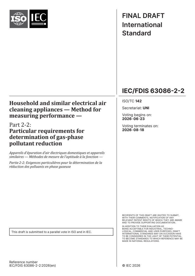

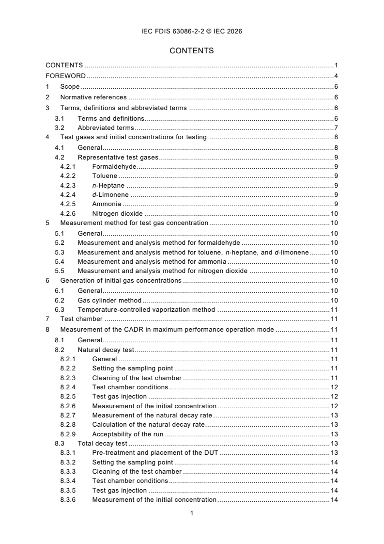
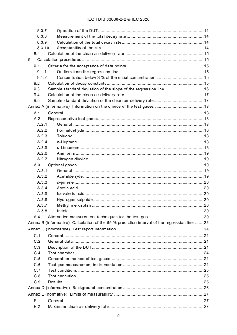
IEC/FDIS 63086-2-2 - Household and similar electrical air cleaning appliances — Method for measuring performance — Part 2-2: Particular requirements for determination of gas-phase pollutant reduction
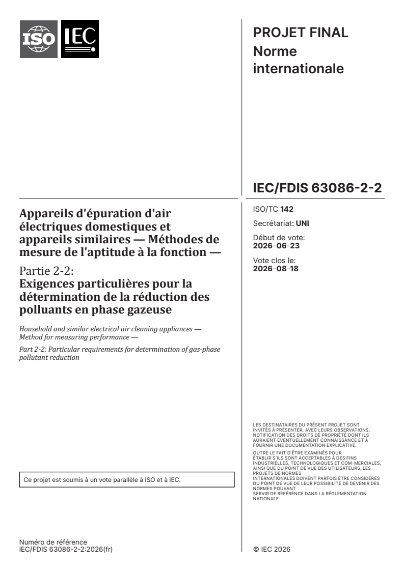

IEC/FDIS 63086-2-2 - Appareils d'épuration d'air électriques domestiques et appareils similaires — Méthodes de mesure de l'aptitude à la fonction — Partie 2-2: Exigences particulières pour la détermination de la réduction des polluants en phase gazeuse
Overview
IEC/FDIS 63086-2-2 is an International Standard developed under ISO/TC 142 that specifies standardized test methods for evaluating the performance of household and similar electrical air cleaning appliances, specifically regarding their ability to reduce gas-phase pollutant concentrations. This part (2-2) addresses the measurement of gas-phase pollutant reduction, enabling consistent and comparable evaluation of air cleaners across global markets.
Designed for electrically powered air cleaners used in homes and similar environments, IEC/FDIS 63086-2-2 is crucial to ensure manufacturers, testing laboratories, and regulators can reliably assess and compare an appliance’s effectiveness in removing chemical gases, contributing to improved indoor air quality and enhanced consumer protection.
Key Topics
Scope & Purpose:
- Applies to household and similar electrical air cleaners intended for the reduction of gas-phase pollutants, such as formaldehyde, toluene, ammonia, and nitrogen dioxide.
- Focuses on quantifying the reduction of specific chemical gases rather than odour intensity.
Test Gases Definition:
- Representative gas-phase pollutants for testing include:
- Aldehydes (formaldehyde)
- Aromatic hydrocarbons (toluene)
- Aliphatic hydrocarbons (n-heptane)
- Cyclic terpenes (d-limonene)
- Inorganic odorant gases (ammonia)
- Inorganic combustion gases (nitrogen dioxide)
- Optional gases and further details are included in Annex A.
- Representative gas-phase pollutants for testing include:
Measurement Methods:
- Outlines procedures for determining the clean air delivery rate (CADR) through controlled tests in laboratory test chambers.
- Specifies appropriate methodologies for generating, maintaining, and measuring pollutant concentrations (e.g., use of gas cylinders or vaporization, chromatography, chemiluminescence analysis).
- Describes calculation methods for natural decay and total decay rates of test gases.
Test Chamber Requirements:
- Details the operational parameters and cleaning protocols for testing chambers to ensure consistent background levels and avoid cross-contamination between tests.
Reporting:
- Guidance on test data reporting to ensure transparency and reproducibility, with required documentation outlined in dedicated annexes.
Applications
Implementing IEC/FDIS 63086-2-2 delivers several practical benefits:
Manufacturers:
- Enables standardized testing and performance claims for air cleaners marketed for gas-phase pollutant removal, building trust with consumers and compliance bodies.
- Facilitates product development tailored to removing targeted chemical pollutants found in indoor environments.
Testing Laboratories:
- Offers a clear, reproducible framework for conducting tests, supporting both research and commercial product evaluations.
- Assists with regulatory compliance checks and certification according to recognized international criteria.
Regulators and Market Surveillance:
- Provides an objective basis for evaluating air cleaner efficacy claims and ensures compliance with indoor air quality regulations.
- Helps inform national and regional regulations referencing international standards for air cleaning technologies.
Consumers and Procurement:
- Assures end-users of valid, comparable information about the effectiveness of air purification products for reducing specific gaseous pollutants.
Related Standards
For comprehensive performance assessment and regulatory alignment, consider the following related references:
- IEC 63086-1:2020 - General methods for measuring air cleaning performance in household and similar appliances.
- IEC 63086-2-1:2024 - Specific requirements for measurement of particle reduction.
- ISO 16000 Series - International standards for indoor air quality testing, including analytical methods for volatile organic compounds (VOC), aldehydes, and other air pollutants.
- ISO 16000-3: Determination of formaldehyde and carbonyl compounds.
- ISO 16000-6: Measurement of organic compounds using thermal desorption and chromatography.
- ISO 16000-9: Emission chamber methods.
Utilizing IEC/FDIS 63086-2-2 together with these standards supports robust, reliable, and globally recognized measurement of air cleaner performance for chemical gas reduction, underpinning both regulatory approval and consumer confidence in air cleaning technologies for healthier indoor environments.
Buy Documents
IEC/FDIS 63086-2-2 - Household and similar electrical air cleaning appliances — Method for measuring performance — Part 2-2: Particular requirements for determination of gas-phase pollutant reduction
IEC/FDIS 63086-2-2 - Appareils d'épuration d'air électriques domestiques et appareils similaires — Méthodes de mesure de l'aptitude à la fonction — Partie 2-2: Exigences particulières pour la détermination de la réduction des polluants en phase gazeuse
Get Certified
Connect with accredited certification bodies for this standard

Institut za varilstvo d.o.o. (Welding Institute)
Slovenia's leading welding institute since 1952. ISO 3834, EN 1090, pressure equipment certification, NDT personnel, welder qualification. Only IIW Au
Sponsored listings
Frequently Asked Questions
IEC/FDIS 63086-2-2 is a draft published by the International Organization for Standardization (ISO). Its full title is "Household and similar electrical air cleaning appliances — Method for measuring performance — Part 2-2: Particular requirements for determination of gas-phase pollutant reduction". This standard covers: This International Standard specifies test methods for measuring the performance of household and similar electrical air cleaners intended for the reduction of chemical gases pollutants.
This International Standard specifies test methods for measuring the performance of household and similar electrical air cleaners intended for the reduction of chemical gases pollutants.
IEC/FDIS 63086-2-2 is classified under the following ICS (International Classification for Standards) categories: 23.120 - Ventilators. Fans. Air-conditioners. The ICS classification helps identify the subject area and facilitates finding related standards.
IEC/FDIS 63086-2-2 is available in PDF format for immediate download after purchase. The document can be added to your cart and obtained through the secure checkout process. Digital delivery ensures instant access to the complete standard document.
Standards Content (Sample)
FINAL DRAFT
International
Standard
ISO/TC 142
Household and similar electrical air
Secretariat: UNI
cleaning appliances — Method for
Voting begins on:
measuring performance —
2026-06-23
Part 2-2:
Voting terminates on:
2026-08-18
Particular requirements for
determination of gas-phase
pollutant reduction
Appareils d'épuration d'air électriques domestiques et appareils
similaires — Méthodes de mesure de l'aptitude à la fonction —
Partie 2-2: Exigences particulières pour la détermination de la
réduction des polluants en phase gazeuse
RECIPIENTS OF THIS DRAFT ARE INVITED TO SUBMIT,
WITH THEIR COMMENTS, NOTIFICATION OF ANY
RELEVANT PATENT RIGHTS OF WHICH THEY ARE AWARE
AND TO PROVIDE SUPPOR TING DOCUMENTATION.
IN ADDITION TO THEIR EVALUATION AS
BEING ACCEPTABLE FOR INDUSTRIAL, TECHNO-
LOGICAL, COMMERCIAL AND USER PURPOSES, DRAFT
This draft is submitted to a parallel vote in ISO and in IEC.
INTERNATIONAL STANDARDS MAY ON OCCASION HAVE
TO BE CONSIDERED IN THE LIGHT OF THEIR POTENTIAL
TO BECOME STAN DARDS TO WHICH REFERENCE MAY BE
MADE IN NATIONAL REGULATIONS.
Reference number
FINAL DRAFT
International
Standard
ISO/TC 142
Household and similar electrical air
Secretariat: UNI
cleaning appliances — Method for
Voting begins on:
measuring performance —
Part 2-2:
Voting terminates on:
Particular requirements for
determination of gas-phase
pollutant reduction
Appareils d'épuration d'air électriques domestiques et appareils
similaires — Méthodes de mesure de l'aptitude à la fonction —
Partie 2-2: Exigences particulières pour la détermination de la
réduction des polluants en phase gazeuse
RECIPIENTS OF THIS DRAFT ARE INVITED TO SUBMIT,
WITH THEIR COMMENTS, NOTIFICATION OF ANY
RELEVANT PATENT RIGHTS OF WHICH THEY ARE AWARE
AND TO PROVIDE SUPPOR TING DOCUMENTATION.
IN ADDITION TO THEIR EVALUATION AS
BEING ACCEPTABLE FOR INDUSTRIAL, TECHNO-
LOGICAL, COMMERCIAL AND USER PURPOSES, DRAFT
This draft is submitted to a parallel vote in ISO and in IEC.
INTERNATIONAL STANDARDS MAY ON OCCASION HAVE
TO BE CONSIDERED IN THE LIGHT OF THEIR POTENTIAL
TO BECOME STAN DARDS TO WHICH REFERENCE MAY BE
MADE IN NATIONAL REGULATIONS.
Reference number
© IEC 2026 – All rights reserved
ii
IEC FDIS 63086-2-2 © IEC 2026
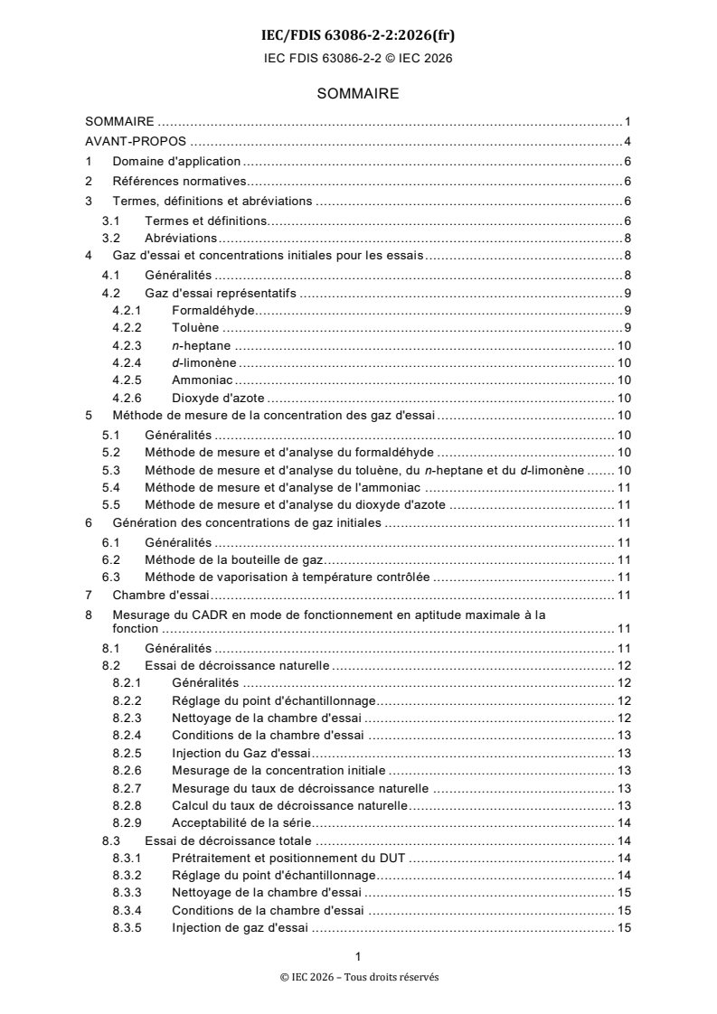
CONTENTS
CONTENTS . 1
FOREWORD . 4
1 Scope . 6
2 Normative references . 6
3 Terms, definitions and abbreviated terms . 6
3.1 Terms and definitions. 6
3.2 Abbreviated terms . 7
4 Test gases and initial concentrations for testing . 8
4.1 General . 8
4.2 Representative test gases . 9
4.2.1 Formaldehyde . 9
4.2.2 Toluene . 9
4.2.3 n-Heptane . 9
4.2.4 d-Limonene . 9
4.2.5 Ammonia . 9
4.2.6 Nitrogen dioxide . 10
5 Measurement method for test gas concentration . 10
5.1 General . 10
5.2 Measurement and analysis method for formaldehyde . 10
5.3 Measurement and analysis method for toluene, n-heptane, and d-limonene . 10
5.4 Measurement and analysis method for ammonia . 10
5.5 Measurement and analysis method for nitrogen dioxide . 10
6 Generation of initial gas concentrations . 10
6.1 General . 10
6.2 Gas cylinder method . 10
6.3 Temperature-controlled vaporization method . 11
7 Test chamber . 11
8 Measurement of the CADR in maximum performance operation mode . 11
8.1 General . 11
8.2 Natural decay test . 11
8.2.1 General . 11
8.2.2 Setting the sampling point . 11
8.2.3 Cleaning of the test chamber . 11
8.2.4 Test chamber conditions . 12
8.2.5 Test gas injection . 12
8.2.6 Measurement of the initial concentration . 12
8.2.7 Measurement of the natural decay rate . 13
8.2.8 Calculation of the natural decay rate. 13
8.2.9 Acceptability of the run . 13
8.3 Total decay test . 13
8.3.1 Pre-treatment and placement of the DUT . 13
8.3.2 Setting the sampling point . 14
8.3.3 Cleaning of the test chamber . 14
8.3.4 Test chamber conditions . 14
8.3.5 Test gas injection . 14
8.3.6 Measurement of the initial concentration . 14
IEC FDIS 63086-2-2 © IEC 2026
8.3.7 Operation of the DUT . 14
8.3.8 Measurement of the total decay rate . 14
8.3.9 Calculation of the total decay rate. 14
8.3.10 Acceptability of the run . 14
8.4 Calculation of the clean air delivery rate . 15
9 Calculation procedures . 15
9.1 Criteria for the acceptance of data points . 15
9.1.1 Outliers from the regression line . 15
9.1.2 Concentration below 3 % of the initial concentration . 15
9.2 Calculation of decay constants . 15
9.3 Sample standard deviation of the slope of the regression line . 16
9.4 Calculation of the clean air delivery rate . 17
9.5 Sample standard deviation of the clean air delivery rate. 17
Annex A (informative) Information on the choice of the test gases . 18
A.1 General . 18
A.2 Representative test gases . 18
A.2.1 General . 18
A.2.2 Formaldehyde . 18
A.2.3 Toluene . 18
A.2.4 n-Heptane . 18
A.2.5 d-Limonene . 18
A.2.6 Ammonia . 19
A.2.7 Nitrogen dioxide . 19
A.3 Optional gases . 19
A.3.1 General . 19
A.3.2 Acetaldehyde . 19
A.3.3 α-pinene . 20
A.3.4 Acetic acid . 20
A.3.5 Isovaleric acid . 20
A.3.6 Hydrogen sulphide . 20
A.3.7 Methyl mercaptan . 20
A.3.8 Indole . 20
A.4 Alternative measurement techniques for the test gas . 20
Annex B (informative) Calculation of the 99 % prediction interval of the regression line . 22
Annex C (informative) Test report information . 24
C.1 General . 24
C.2 General data . 24
C.3 Description of the DUT . 24
C.4 Test chamber . 24
C.5 Generation method of test gases . 24
C.6 Test gas measurement instrumentation . 24
C.7 Test conditions . 25
C.8 Test execution . 25
C.9 Results . 25
Annex D (informative) Background concentration . 26
Annex E (normative) Limits of measurability . 27
E.1 General . 27
E.2 Maximum clean air delivery rate . 27
IEC FDIS 63086-2-2 © IEC 2026
E.3 Minimum clean air delivery rate. 27
Annex F (informative) Schematic representation of a CADR measurement. 28
Annex G (normative) Particular requirements for determination of ozone reduction . 29
G.1 General . 29
G.2 Measurement method for test gas concentration . 29
G.3 Generation of initial gas concentrations . 29
G.4 Measurement of the CADR in maximum performance operation mode . 29
Bibliography . 30
Figure F.1 – Schematic representation of the CADR measurement in accordance with
Clause 8 . 28
Table 1 – Representative test gases . 8
Table 2 – Target of the background concentration of test gases . 12
Table 3 – Limits for the sample standard deviation of the slope of the regression line
for the natural decay . 13
Table 4 – Limits for the sample standard deviation of the slope of the regression line
for the total decay . 14
Table A.1 – Test gases . 19
Table A.2 – Alternative instruments . 20
Table B.1 – Values of the Student t-distribution with df=n-2 degrees of freedom for
different numbers of pairs of data points n . 23
Table D.1 – Background concentration measurement results . 26
Table E.1 – Minimum CADR measurable for the test gases . 27
IEC FDIS 63086-2-2 © IEC 2026
INTERNATIONAL ELECTROTECHNICAL COMMISSION
____________
Household and similar electrical air cleaning appliances - Method for
measuring the performance -
Part 2-2: Particular requirements for determination of gas-phase pollutant
reduction
FOREWORD
1) The International Electrotechnical Commission (IEC) is a worldwide organization for
standardization comprising all national electrotechnical committees (IEC National Committees).
The object of IEC is to promote international co-operation on all questions concerning
standardization in the electrical and electronic fields. To this end and in addition to other
activities, IEC publishes International Standards, Technical Specifications, Technical Reports,
Publicly Available Specifications (PAS) and Guides (hereafter referred to as "IEC
Publication(s)"). Their preparation is entrusted to technical committees; any IEC National
Committee interested in the subject dealt with may participate in this preparatory work.
International, governmental and non-governmental organizations liaising with the IEC also
participate in this preparation. IEC collaborates closely with the International Organization for
Standardization (ISO) in accordance with conditions determined by agreement between the two
organizations.
2) The formal decisions or agreements of IEC on technical matters express, as nearly as
possible, an international consensus of opinion on the relevant subjects since each technical
committee has representation from all interested IEC National Committees.
3) IEC Publications have the form of recommendations for international use and are accepted
by IEC National Committees in that sense. While all reasonable efforts are made to ensure that
the technical content of IEC Publications is accurate, IEC cannot be held responsible for the
way in which they are used or for any misinterpretation by any end user.
4) In order to promote international uniformity, IEC National Committees undertake to apply IEC
Publications transparently to the maximum extent possible in their national and regional
publications. Any divergence between any IEC Publication and the corres ponding national or
regional publication shall be clearly indicated in the latter.
5) IEC itself does not provide any attestation of conformity. Independent certification bodies
provide conformity assessment services and, in some areas, access to IEC marks of conformity.
IEC is not responsible for any services carried out by independent certification bodies.
6) All users should ensure that they have the latest edition of this publication.
7) No liability shall attach to IEC or its directors, employees, servants or agents including
individual experts and members of its technical committees and IEC National Committees for
any personal injury, property damage or other damage of any nature whatsoever, whether direct
or indirect, or for costs (including legal fees) and expenses arising out of the publication, use
of, or reliance upon, this IEC Publication or any other IEC Publications.
8) Attention is drawn to the Normative references cited in this publication. Use of the referenced
publications is indispensable for the correct application of this publication.
9) IEC draws attention to the possibility that the implementation of this document may involve
the use of (a) patent(s). IEC takes no position concerning the evidence, validity or applicability
IEC FDIS 63086-2-2 © IEC 2026
of any claimed patent rights in respect thereof. As of the date of publication of this document,
IEC had not received notice of (a) patent(s), which may be required to implement this document.
However, implementers are cautioned that this may not represent the latest information, which
may be obtained from the patent database available at https://patents.iec.ch. IEC shall not be
held responsible for identifying any or all such patent rights.
IEC 63086-2-2 has been prepared by subcommittee 59N: Electrical air cleaners for household
and similar purposes, of IEC technical committee 59: Performance of household and similar
electrical appliances, in co-operation with ISO technical committee 142: Cleaning equipment
for air and other gases and ISO technical committee 146: Air quality. It is an International
Standard.
It is published as a double logo International Standard.
The text of this International Standard is based on the following documents:
Draft Report on voting
59N/XX/FDIS 59N/XX/RVD
Full information on the voting for its approval can be found in the report on voting indicated in
the above table.
The language used for the development of this International Standard is English.
This document was drafted in accordance with ISO/IEC Directives, Part 2, and developed in
accordance with ISO/IEC Directives, Part 1 and ISO/IEC Directives, IEC Supplement, available
at www.iec.ch/members_experts/refdocs. The main document types developed by IEC are
described in greater detail at www.iec.ch/publications.
A list of all parts in the IEC 63086 series, published under the general title Household and
similar electrical air cleaning appliances - Methods for measuring the performance, can be
found on the IEC website.
The committee has decided that the contents of this document will remain unchanged until the
stability date indicated on the IEC website under webstore.iec.ch in the data related to the
specific document. At this date, the document will be
– reconfirmed,
– withdrawn, or
– revised.
IEC FDIS 63086-2-2 © IEC 2026
1 Scope
This part of IEC 63086 specifies test methods for measuring the performance of electrically
powered household and similar air cleaners intended for the reduction of gas-phase pollutants.
This document is intended for measuring the reduction of the concentration of specific gas-
phase pollutants. This does not necessarily correlate with the reduction of odour intensity in the
case of odorous gas-phase pollutants. Such a reduction can only be tested by olfactory tests,
which are not part of this document.
NOTE Test methods for the determination of possible gas-phase by-products are under consideration.
2 Normative references
The following documents are referred to in the text in such a way that some or all of their content
constitutes requirements of this document. For dated references, only the edition cited applies.
For undated references, the latest edition of the referenced document (including any
amendments) applies.
IEC 63086-1:2020, Household and similar electrical air cleaning appliances - Methods for
measuring the performance - Part 1: General requirements
IEC 63086-2-1:2024, Household and similar electrical air cleaning appliances - Methods for
measuring the performance - Part 2-1: Particular requirements for determination of reduction of
particles
ISO 16000-3, Indoor air - Part 3: Determination of formaldehyde and other carbonyl compounds
in indoor air and test chamber air - Active sampling method
ISO 16000-3:2022, Indoor air — Part 3: Determination of formaldehyde and other carbonyl
compounds in indoor and test chamber air — Active sampling method
ISO 16000-6, Indoor air - Part 6: Determination of organic compounds (VVOC, VOC, SVOC) in
indoor and test chamber air by active sampling on sorbent tubes, thermal desorption and gas
chromatography using MS or MSFID
ISO 16000-9, Indoor air - Part 9: Determination of the emission of volatile organic compounds
from building products and furnishing - Emission test chamber method
3 Terms, definitions and abbreviated terms
3.1 Terms and definitions
For the purposes of this document, the terms and definitions given in IEC 63086-1:2020 and
the following apply.
ISO and IEC maintain terminology databases for use in standardization at the following
addresses:
– IEC Electropedia: available at https://www.electropedia.org/
– ISO Online browsing platform: available at https://www.iso.org/obp
3.1.1
gas-phase pollutant
gaseous compound found in indoor environments as a result of outdoor air infiltration, indoor
human activities, or emissions from indoor materials
IEC FDIS 63086-2-2 © IEC 2026
3.1.2
test gas
gas-phase pollutant (3.1.1) selected for measuring the performance of air cleaners
3.1.3
natural decay rate
reduction rate of the test gas (3.1.2) in the test chamber due to natural factors, such as surface
adsorption, chemical reaction, and air exchange
−1
Note 1 to entry: The unit is per hour (h ).
3.1.4
total decay rate
reduction rate of the test gas (3.1.2) in the test chamber due to the combined effect of the
natural decay rate (3.1.3) and the operation decay rate
−1
Note 1 to entry: The unit is per hour (h ).
3.1.5
background concentration
concentration of test gases (3.1.2) in the test chamber after the test chamber has undergone
cleaning and prior to the injection of test gases (3.1.2)
3.1.6
initial concentration
concentration measured inside the test chamber after the injection and mixing of test gases
(3.1.2)
3.1.7
TVOC
total volatile organic compounds
sum of the concentrations of identified and unidentified volatile organic compounds eluting
between and including n-hexane and n-hexadecane (in accordance with ISO 16000-9)
3.1.8
real-time measurement method
method for determining the concentration of the test gas (3.1.2) using a direct reading
instrument
Note 1 to entry: A chemiluminescence analyser is an example for an instrument using a real-time measurement
method.
3.1.9
integrated sampling method
method for determining the concentration of the test gas (3.1.2) by a periodic process of air
capture and subsequent analysis of the sample
Note 1 to entry: High performance liquid chromatography (HPLC) is an example of an instrument using an integrated
sampling method (3.1.9).
3.2 Abbreviated terms
CADR clean air delivery rate
DNPH 2,4- dinitrophenylhydrazine
DUT device under test
FID flame ionization detector
GC gas chromatography
HPLC high performance liquid chromatography
IEC FDIS 63086-2-2 © IEC 2026
IC ion chromatography
MS mass spectrometry
PTFE polytetrafluoroethylene
SIFT-MS selected ion flow tube mass spectrometry
TVOC total volatile organic compounds
4 Test gases and initial concentrations for testing
4.1 General
Gas-phase pollutants are in the context of this document classified into 6 groups as a)
aldehydes, b) aromatic hydrocarbons, c) aliphatic hydrocarbons, d) cyclic terpenes, e) inorganic
odorant gases and f) inorganic combustion gases. The test gases representing each group are
described in Table 1 in accordance with factors considered comprehensively such as commonly
observed as indoor pollutants, suitability for standard test methods in terms of availability and
stability.
The CADR of an air cleaner generally depends on the test gases, and individual representative
test gases differ in appropriate initial concentration, generation method, and measurement
method of concentration. It is not mandatory to perform tests with all representative test gases,
but individual ones relevant for the specific application may be chosen. Also, other test gases
which are not described as representative test gas may be chosen. For examples, see Annex
A. Optional testing for reduction of ozone by an air cleaner shall be performed in accordance
with Annex G.
NOTE 1 It is known that the CADR can depend on the initial concentration. However, the focus of this document is
to compare different air cleaners under the same test conditions. Therefore, the values listed in Table 1 can be used.
If different initial concentrations are used, they can be clearly stated as a deviation from the standard in the test
report.
The laboratory may select to test each gas individually. If this method is chosen, the laboratory
shall choose a test sequence that avoids changing the performance of the technology tested
from one test to another. Multiple test gases may be dosed at the same time for parallel
measurement of the CADR if they do not react with each other or modify the performance of
the technology tested regarding the pollutant(s) tested. For example, toluene, n-heptane and
d-limonene may be tested in parallel. However, formaldehyde shall not be tested with ammonia
as they react with each other. In the case it is possible for gases to react with each other or in
the case it is possible for a gas to modify the performance of the technology regarding the gas
tested after they are used in two consecutive tests, the filter of the DUT shall be changed
between the measurements if it is replaceable. Otherwise, the DUT shall be operated in the test
chamber while the test chamber air treatment unit is running until the background concentration
is below the values described in 8.2.3.
Table 1 – Representative test gases
Group of gas-phase pollutants Representative test gas Initial concentration
a) Aldehydes
Formaldehyde
+20%
−3
400 µg m
0%
b) Aromatic hydrocarbons
Toluene
+20%
−3
800 µg m
0%
c) Aliphatic hydrocarbons
n-Heptane
+20%
−3
800 µg m
0%
d) Cyclic terpenes
d-Limonene
+20%
−3
800 µg m
0%
IEC FDIS 63086-2-2 © IEC 2026
Group of gas-phase pollutants Representative test gas Initial concentration
e) Inorganic odorant gases
Ammonia
+20%
−3
700 µg m
0%
f) Inorganic combustion gases
Nitrogen dioxide
+20%
−3
500 µg m
0%
NOTE 2 Technical methods such as adsorption (physical or chemical) and decomposition (for example oxidation)
are used for removal of gas-phase pollutants. Gas-phase pollutants have different physical and chemical properties,
for example, polar or non polar, acidic or basic, vapour pressure, resistance to decomposition by oxidative
substances. Air cleaner's performance for removal of each target gas-phase pollutant differs by the combination of
substance and technical method of removal. The performance for removal of one kind of gas-phase pollutants can
not be applied to the other gas-phase pollutants.
NOTE 3 Testing individual test gases. An example of sequence that can be applied for adsorption technology is:
(cleaning) → Toluene → (cleaning) → d-Limonene → (cleaning) → n-Heptane → (cleaning) → Ammonia → (cleaning)
→ Formaldehyde → (cleaning) → Nitrogen dioxide → (cleaning). Testing in combination. If the laboratory has the
measurement instruments that are capable of measuring and delineating quantities of Toluene, d-Limonene, and n-
Heptane from each other, the laboratory can elect to test these three chemicals at the same time. In this case, an
example of sequence for adsorption technology would be: (cleaning) → [combination of Toluene, d-Limonene and n-
Heptane] → (cleaning) → Ammonia → (cleaning) → Formaldehyde → (cleaning) → Nitrogen dioxide → (cleaning).
NOTE 4 The information of optional gases such as acetaldehyde is described in Annex A.
NOTE 5 More information on the background can be found in Annex D.
NOTE 6 Particular requirements for determination of ozone reduction are described in Annex G.
4.2 Representative test gases
4.2.1 Formaldehyde
Use commercial formaldehyde gas mixed with nitrogen (N ) for the gas cylinder method, or an
aqueous solution of formaldehyde (formalin, CAS 50-00-0, methanol free) or solid
paraformaldehyde (CAS 30525-89-4) with at least 90,0 % for the temperature-controlled
vaporization method.
4.2.2 Toluene
Use commercial toluene gas mixed with nitrogen (N ) for the gas cylinder method, or liquid-
phase toluene (CAS 108-88-3) with at least 99,9 % GC grade purity for the temperature-
controlled vaporization method.
4.2.3 n-Heptane
Use commercial n-heptane gas mixed with nitrogen (N ) for the gas cylinder method, or liquid-
phase n-heptane (CAS 142-82-5) with at least 99,0 % GC grade purity for the temperature-
controlled vaporization method.
4.2.4 d-Limonene
Use commercial d-limonene gas mixed with nitrogen (N ) for the gas cylinder method, or liquid-
phase d-limonene (CAS 5989-27-5) with at least 95 % purity for the temperature-controlled
vaporization method initial concentration.
4.2.5 Ammonia
Use commercial ammonia gas mixed with nitrogen (N ) for the gas cylinder method, or an
aqueous ammonia solution for the temperature-controlled vaporization method.
IEC FDIS 63086-2-2 © IEC 2026
4.2.6 Nitrogen dioxide
Use commercial nitrogen dioxide gas mixed with nitrogen (N ) for the gas cylinder method.
5 Measurement method for test gas concentration
5.1 General
The measurement method for each substance is specified as follows. If it is confirmed that an
alternative method has the same or higher accuracy than the specified method, it may be used.
Information on alternative methods can be found in Annex A.
For the case that a CADR measurement is performed with nitrogen dioxide, the concentration
of nitrogen oxide shall be monitored in parallel as there can be conversion processes between
the two gases.
Maintenance of all measurement instruments shall be done as defined by the manufacturer´s
instructions. Calibration of the instruments with gas standards shall be regularly performed in
accordance with the standard operating procedures of the laboratory.
5.2 Measurement and analysis method for formaldehyde
According to ISO 16000-3, silica gel coated with 2,4-dinitrophenylhydrazine (DNPH) cartridges
and high-performance liquid chromatography (HPLC) shall be used for the measurement and
analysis of formaldehyde. In tests where there is a possibility that oxidative substances such
as ozone are generated, the ozone scrubber described in ISO 16000-3:2022, 5.2 shall be
installed in front of the DNPH cartridge.
5.3 Measurement and analysis method for toluene, n-heptane, and d-limonene
According to ISO 16000-6, thermal desorption tubes and either gas chromatography / mass
spectrometry (GC/MS) or gas chromatography / flame ionization detector (GC/FID) shall be
used for the measurement and analysis of toluene, n-heptane and d-limonene. Selected ion
flow tube mass spectrometry (SIFT-MS) may be used instead of GC/MS or GC/FID.
5.4 Measurement and analysis method for ammonia
Distilled water and ion chromatography (IC) or a chemiluminescence analyser shall be used for
the measurement and analysis of ammonia.
5.5 Measurement and analysis method for nitrogen dioxide
A chemiluminescence analyser shall be used for the measurement and analysis of nitrogen
dioxide.
6 Generation of initial gas concentrations
6.1 General
Each test gas is supplied into the test chamber either by the gas cylinder method or the
temperature-controlled vaporization method and adjusted to the initial concentration defined in
4.2.
6.2 Gas cylinder method
The test gas in the cylinder, which has been adjusted to a predetermined concentration in
advance by nitrogen balance, is supplied into the test chamber using an appropriate regulator
through a polytetrafluoroethylene (PTFE) or stainless-steel tube.
IEC FDIS 63086-2-2 © IEC 2026
6.3 Temperature-controlled vaporization method
The high-purity reagent of the test gas is placed in a temperature-controlled permeation tube,
diffusion tube or other injection system for vaporization. Filtered air or nitrogen gas is used as
a carrier gas to supply the test gas into the test chamber.
7 Test chamber
The test chamber is in accordance with IEC 63086-1:2020, 5.6 except for the following changes:
3 −1 3
The wall-mounted recirculation fan shall have a flow rate of between 300 m h and 500 m
−1 −1
h and a maximum airspeed of 15 m s measured at the centre of the fan exhaust at 0,5 m
from the face.
NOTE The recirculation flow rate for gas-phase testing is adjusted to maintain representative and controlled
chamber distributions. Too much flow rate can incur the risk of too high performance for the air -cleaner with low air
flow rate including fan-less type. A higher recirculation flow rate is used for testing of course particulates to maintain
particles in suspension and to ensure uniform concentrations.
8 Measurement of the CADR in maximum performance operation mode
8.1 General
Perform the test procedure in 8.2 (natural decay rate) and 8.3 (total decay rate) to determine
the CADR of the DUT.
NOTE 1 The items to be included in the test report are described in Annex C.
NOTE 2 The graphical scheme of the test procedure is shown in Annex F.
8.2 Natural decay test
8.2.1 General
Natural decay test shall be carried out without placement of the DUT to keep away the influence
of the contamination by the gas-phase pollutants.
It is permissible to apply the results of a natural decay test performed within one week prior to
the total decay test.
8.2.2 Setting the sampling point
Set the sampling point in accordance with IEC 63086-1:2020, 5.6.2. The sampling point shall
be connected to a DNPH cartridge, a thermal desorption tube or an instrument for the real-time
measurement method outside the test chamber with a PTFE or stainless-steel tube.
NOTE For integrated sampling methods, the following procedure is used as an example to minimize adsorption and
desorption effects within the tubing by reducing the tube length between the sampling point and the sampling device.
A tube is connected from the sampling pump to a sampling device (e.g., a cartridge or a thermal desorption tube)
located outside the test chamber. The sampling device is mounted on a rod or similar support and adjusted so that
its tip is positioned precisely at the sampling point when inserted. The device is introduced into the chamber through
an opening only during active sampling and is otherwise kept outside the test chamber.
8.2.3 Cleaning of the test chamber
Start operating the mixing fan and recirculation fan. The recirculation fan will continue to
operate for the duration of the cleaning procedure. Using the filtration part of the test chamber
air treatment unit, allow the test chamber air to clean until the background concentration of the
test gas to be tested reaches a level below the values indicated in Table 2. If the background
concentration does not reach a level below the target due to the contamination on inner surfaces
of the test chamber, cleaning may be done by washing the inner surfaces of the test chamber
IEC FDIS 63086-2-2 © IEC 2026
with an alkaline detergent followed by two separate rinsing cycles with freshly distilled water.
The test chamber is then dried and purged at environmental conditions using the chambers
filtration and exhaust system until the background concentration levels meet the requirements
in Table 2.
NOTE 1 To ensure that the cleaning procedure is also working for other gases than the test gas, regularly check
that the TVOC background level is below the value indicated in Table 2.
Table 2 – Target of the background concentration of test gases
Test gas Target concentration
−3
Formaldehyde
12 µg m
−3
Toluene
24 µg m
−3
n-Heptane
24 µg m
−3
d-Limonene
24 µg m
−3
Ammonia
7 µg m
−3
Nitrogen dioxide
19 µg m
−3
TVOC
50 µg m
In the case of the test for reduction of d-limonene, the background concentration of ozone
−3
should be below 7 ppb (14 µg m at (23 ± 3) ℃) and be monitored during the test.
When an acceptable background concentration in the test chamber is reached, turn off the
filtration part of the test chamber air treatment unit and record the background concentration.
NOTE 2 For integrated sampling methods such as DNPH/HPLC, the background concentration can only be checked
after the test.
NOTE 3 Cleaning methods can be found in ISO 16000-9 [1].
NOTE 4 The TVOC value is calculated according to ISO 16000-6 [2].
8.2.4 Test chamber conditions
During the cleaning of the test chamber, per 8.2.3, operate the conditioning equipment of the
chamber, until temperature and relative humidity are as specified in IEC 63086-1:2020, 5.2.1.
When the required values are reached, turn off the conditioning part of the test chamber air
treatment unit. Record the relative humidity and temperature of the test chamber during the
whole test period. Values outside the limits invalidate the run.
8.2.5 Test gas injection
When the test chamber air treatment unit is switched off, start supplying the test gas into the
test chamber as described in Clause 6 until the initial concentration reaches the value described
in 4.2. After reaching the required value, turn off the test gas injection system and close the
test chamber valve.
8.2.6 Measurement of the initial concentration
After the test gas injection is turned off, mix the test gas in the test chamber for 1 minute and
turn off the mixing fan. Wait for 5 minutes for homogenization of the test gas inside the test
chamber. Measure the initial concentration of the test gas during the homogenization time. If
the initial concentration is not within the limits described in 4.2, terminate the run.
NOTE For integrated sampling methods such as DNPH/HPLC, the initial concentration is only able to be checked
after the test. The appropriate test gas generation conditions such as flow rate, concentration, time, etc., are
confirmed through prior test.
IEC FDIS 63086-2-2 © IEC 2026
8.2.7 Measurement of the natural decay rate
After the measurement of the initial concentration has been completed, wait for 1 minute before
starting to acquire test gas. Then the sample air in the test chamber is collected or the
concentration in the test chamber is measured every 5 minutes until 60 minutes later. Shorter
interval time (for example, 1 minute) for measuring may be selected according to the accuracy
of the method for measuring concentration of the test gas. At least six acceptable data points
are required. For sampling which uses draw samples for GC-MS/HPLC tubes, samples are
taken at 5 minutes intervals. For the purpose of graphing or displaying the data, the times above
should be the midpoints of the air sampling. Even if a short measurement interval is selected
using real-time measurement method, the minimum testing duration should be 10 minutes,
taking into account that at least six data points are required at 1-minute intervals. The time
stamp allocated to the first data point defines t = 0 in the calculation of the natural decay rate.
8.2.8 Calculation of the natural decay rate
Calculate the natural decay rate as described in 9.2.
8.2.9 Acceptability of the run
Calculate the sample standard deviation of the slope of the regression line for the natural decay
in accordance with 9.3. A sample standard deviation less than the values indicated in Table 3
determines the acceptability of the run.
Table 3 – Limits for the sample standard deviation of the slope of the regression line for
the natural decay
−1
Test gas
Limit for sample standard deviation (h )
Formaldehyde 0,1
Toluene 0,1
n-Heptane 0,1
d-Limonene 0,1
Ammonia 0,1
Nitrogen dioxide 0,1
8.3 Total decay test
8.3.1 Pre-treatment and placement of the DUT
Inspect the DUT for shipping damages or other obvious visual defects. Prior to the initial test,
the motor of DUT shall be properly broken in by running the DUT per manufacturer’s instructions
for a minimum of 48 h. For DUT including a UV lamp, the lamp shall be burned in for 100 hours
if not stated otherwise by the manufacturer's instructions.
The run-in time of the DUT should be conducted in an environment with the least amount of test
gas concentration possible. While removable filters will not be used during the run-in time, it is
not always possible to agree to exchange the components in all technologies. The DUT shall
not be exposed by elevated test gas concentrations above the minimum background levels.
Filters and other parts of the DUT which are referenced in the instruction manual as replaceable
shall be removed during the run-in period. If the DUT will not operate without these replaceable
parts installed or if the
...
PROJET FINAL
Norme
internationale
ISO/TC 142
Appareils d'épuration d'air
Secrétariat: UNI
électriques domestiques et
Début de vote:
appareils similaires — Méthodes de
2026-06-23
mesure de l'aptitude à la fonction —
Vote clos le:
2026-08-18
Partie 2-2:
Exigences particulières pour la
détermination de la réduction des
polluants en phase gazeuse
Household and similar electrical air cleaning appliances —
Method for measuring performance —
Part 2-2: Particular requirements for determination of gas-phase
pollutant reduction
LES DESTINATAIRES DU PRÉSENT PROJET SONT
INVITÉS À PRÉSENTER, AVEC LEURS OBSERVATIONS,
NOTIFICATION DES DROITS DE PROPRIÉTÉ DONT ILS
AURAIENT ÉVENTUELLEMENT CONNAISSANCE ET À
FOURNIR UNE DOCUMENTATION EXPLICATIVE.
OUTRE LE FAIT D’ÊTRE EXAMINÉS POUR
ÉTABLIR S’ILS SONT ACCEPTABLES À DES FINS
INDUSTRIELLES, TECHNOLOGIQUES ET COM-MERCIALES,
AINSI QUE DU POINT DE VUE DES UTILISATEURS, LES
PROJETS DE NORMES
INTERNATIONALES DOIVENT PARFOIS ÊTRE CONSIDÉRÉS
Ce projet est soumis à un vote parallèle à ISO et à IEC.
DU POINT DE VUE DE LEUR POSSI BILITÉ DE DEVENIR DES
NORMES POUVANT
SERVIR DE RÉFÉRENCE DANS LA RÉGLEMENTATION
NATIONALE.
Numéro de référence
PROJET FINAL
Norme
internationale
ISO/TC 142
Appareils d'épuration d'air
Secrétariat: UNI
électriques domestiques et
Début de vote:
appareils similaires — Méthodes de
2026-06-23
mesure de l'aptitude à la fonction —
Vote clos le:
2026-08-18
Partie 2-2:
Exigences particulières pour la
détermination de la réduction des
polluants en phase gazeuse
Household and similar electrical air cleaning appliances —
Method for measuring performance —
Part 2-2: Particular requirements for determination of gas-phase
pollutant reduction
LES DESTINATAIRES DU PRÉSENT PROJET SONT
INVITÉS À PRÉSENTER, AVEC LEURS OBSERVATIONS,
NOTIFICATION DES DROITS DE PROPRIÉTÉ DONT ILS
AURAIENT ÉVENTUELLEMENT CONNAISSANCE ET À
FOURNIR UNE DOCUMENTATION EXPLICATIVE.
OUTRE LE FAIT D’ÊTRE EXAMINÉS POUR
ÉTABLIR S’ILS SONT ACCEPTABLES À DES FINS
INDUSTRIELLES, TECHNOLOGIQUES ET COM-MERCIALES,
AINSI QUE DU POINT DE VUE DES UTILISATEURS, LES
PROJETS DE NORMES
INTERNATIONALES DOIVENT PARFOIS ÊTRE CONSIDÉRÉS
Ce projet est soumis à un vote parallèle à ISO et à IEC.
DU POINT DE VUE DE LEUR POSSI BILITÉ DE DEVENIR DES
NORMES POUVANT
SERVIR DE RÉFÉRENCE DANS LA RÉGLEMENTATION
NATIONALE.
Numéro de référence
© IEC 2026 – Tous droits réservés
ii
IEC FDIS 63086-2-2 © IEC 2026
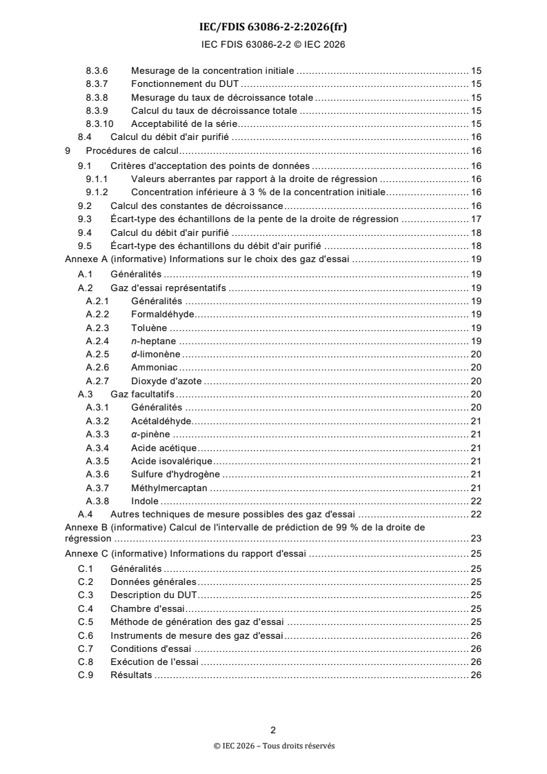
SOMMAIRE
SOMMAIRE . 1
AVANT-PROPOS . 4
1 Domaine d'application . 6
2 Références normatives . 6
3 Termes, définitions et abréviations . 6
3.1 Termes et définitions. 6
3.2 Abréviations . 8
4 Gaz d'essai et concentrations initiales pour les essais . 8
4.1 Généralités . 8
4.2 Gaz d'essai représentatifs . 9
4.2.1 Formaldéhyde. 9
4.2.2 Toluène . 9
4.2.3 n-heptane . 10
4.2.4 d-limonène . 10
4.2.5 Ammoniac . 10
4.2.6 Dioxyde d'azote . 10
5 Méthode de mesure de la concentration des gaz d'essai . 10
5.1 Généralités . 10
5.2 Méthode de mesure et d'analyse du formaldéhyde . 10
5.3 Méthode de mesure et d'analyse du toluène, du n-heptane et du d-limonène . 10
5.4 Méthode de mesure et d'analyse de l'ammoniac . 11
5.5 Méthode de mesure et d'analyse du dioxyde d'azote . 11
6 Génération des concentrations de gaz initiales . 11
6.1 Généralités . 11
6.2 Méthode de la bouteille de gaz . 11
6.3 Méthode de vaporisation à température contrôlée . 11
7 Chambre d'essai . 11
8 Mesurage du CADR en mode de fonctionnement en aptitude maximale à la
fonction . 11
8.1 Généralités . 11
8.2 Essai de décroissance naturelle . 12
8.2.1 Généralités . 12
8.2.2 Réglage du point d'échantillonnage. 12
8.2.3 Nettoyage de la chambre d'essai . 12
8.2.4 Conditions de la chambre d'essai . 13
8.2.5 Injection du Gaz d'essai . 13
8.2.6 Mesurage de la concentration initiale . 13
8.2.7 Mesurage du taux de décroissance naturelle . 13
8.2.8 Calcul du taux de décroissance naturelle . 13
8.2.9 Acceptabilité de la série. 14
8.3 Essai de décroissance totale . 14
8.3.1 Prétraitement et positionnement du DUT . 14
8.3.2 Réglage du point d'échantillonnage. 14
8.3.3 Nettoyage de la chambre d'essai . 15
8.3.4 Conditions de la chambre d'essai . 15
8.3.5 Injection de gaz d'essai . 15
© IEC 2026 – Tous droits réservés
IEC FDIS 63086-2-2 © IEC 2026
8.3.6 Mesurage de la concentration initiale . 15
8.3.7 Fonctionnement du DUT . 15
8.3.8 Mesurage du taux de décroissance totale . 15
8.3.9 Calcul du taux de décroissance totale . 15
8.3.10 Acceptabilité de la série. 15
8.4 Calcul du débit d'air purifié . 16
9 Procédures de calcul. 16
9.1 Critères d'acceptation des points de données . 16
9.1.1 Valeurs aberrantes par rapport à la droite de régression . 16
9.1.2 Concentration inférieure à 3 % de la concentration initiale. 16
9.2 Calcul des constantes de décroissance . 16
9.3 Écart-type des échantillons de la pente de la droite de régression . 17
9.4 Calcul du débit d'air purifié . 18
9.5 Écart-type des échantillons du débit d'air purifié . 18
Annexe A (informative) Informations sur le choix des gaz d'essai . 19
A.1 Généralités . 19
A.2 Gaz d'essai représentatifs . 19
A.2.1 Généralités . 19
A.2.2 Formaldéhyde. 19
A.2.3 Toluène . 19
A.2.4 n-heptane . 19
A.2.5 d-limonène . 20
A.2.6 Ammoniac . 20
A.2.7 Dioxyde d'azote . 20
A.3 Gaz facultatifs . 20
A.3.1 Généralités . 20
A.3.2 Acétaldéhyde. 21
A.3.3 α-pinène . 21
A.3.4 Acide acétique . 21
A.3.5 Acide isovalérique . 21
A.3.6 Sulfure d'hydrogène . 21
A.3.7 Méthylmercaptan . 21
A.3.8 Indole . 22
A.4 Autres techniques de mesure possibles des gaz d'essai . 22
Annexe B (informative) Calcul de l'intervalle de prédiction de 99 % de la droite de
régression . 23
Annexe C (informative) Informations du rapport d'essai . 25
C.1 Généralités . 25
C.2 Données générales . 25
C.3 Description du DUT . 25
C.4 Chambre d'essai . 25
C.5 Méthode de génération des gaz d'essai . 25
C.6 Instruments de mesure des gaz d'essai . 26
C.7 Conditions d'essai . 26
C.8 Exécution de l'essai . 26
C.9 Résultats . 26
© IEC 2026 – Tous droits réservés
IEC FDIS 63086-2-2 © IEC 2026
Annexe D (informative) Concentration de fond . 27
Annexe E (normative) Limites de mesurabilité . 28
E.1 Généralités . 28
E.2 Débit d'air purifié maximal . 28
E.3 Débit d'air purifié minimal . 28
Annexe F (informative) Représentation schématique d'un mesurage du CADR . 29
Annexe G (normative) Exigences particulières pour la détermination de la réduction
d'ozone . 30
G.1 Généralités . 30
G.2 Méthode de mesure de la concentration des gaz d'essai . 30
G.3 Génération des concentrations de gaz initiales . 30
G.4 Mesurage du CADR en mode de fonctionnement en aptitude maximale à la
fonction . 30
Bibliographie . 31
Figure F.1 – Représentation schématique du mesurage du CADR selon l'Article 8 . 29
Tableau 1 – Gaz d'essai représentatifs . 9
Tableau 2 – Cible de la concentration de fond des gaz d'essai . 12
Tableau 3 – Limites de l'écart-type des échantillons de la pente de la droite de
régression pour la décroissance naturelle . 14
Tableau 4 – Limites de l'écart-type des échantillons de la pente de la droite de
régression pour la décroissance totale . 15
Tableau A.1 – Gaz d'essai . 20
Tableau A.2 – Autres instruments de mesure possibles . 22
Tableau B.1 – Valeurs de la distribution t de Student avec df=n-2 degrés de liberté
pour différents nombres de paires de points de données n . 24
Tableau D.1 – Mesures de la concentration de fond . 27
Tableau E.1 – CADR minimal mesurable pour les gaz d'essai . 28
© IEC 2026 – Tous droits réservés
IEC FDIS 63086-2-2 © IEC 2026
COMMISSION ÉLECTROTECHNIQUE INTERNATIONALE
____________
Appareils d'épuration d'air électriques domestiques et appareils
similaires – Méthodes de mesure de l'aptitude à la fonction –
Partie 2-2: Exigences particulières pour la détermination de la réduction
des polluants en phase gazeuse
AVANT-PROPOS
1) La Commission Électrotechnique Internationale (IEC) est une organisation mondiale de
normalisation composée de l'ensemble des comités électrotechniques nationaux (Comités
nationaux de l'IEC). L'IEC a pour objet de favoriser la coopération internationale pour toutes
les questions de normalisation dans les domaines de l'électricité et de l'électronique. À cet
effet, l'IEC – entre autres activités – publie des Normes internationales, des Spécifications
techniques, des Rapports techniques, des Spécifications accessibles au public (PAS) et des
Guides (ci-après dénommés "Publication(s) de l'IEC"). Leur élaboration est confiée à des
comités d'études, aux travaux desquels tout Comité national intéressé par le sujet traité peut
participer. Les organisations internationales, gouvernementales et non gouvernementales,
en liaison avec l'IEC, participent également aux travaux. L'IEC collabore étroitement avec
l'Organisation Internationale de Normalisation (ISO), selon des conditions fixées par accord
entre les deux organisations.
2) Les décisions ou accords officiels de l'IEC concernant les questions techniques représentent,
dans la mesure du possible, un accord international sur les sujets étudiés, étant donné que
les Comités nationaux de l'IEC intéressés sont représentés dans chaque comité d'études.
3) Les Publications de l'IEC se présentent sous la forme de recommandations internationales
et sont agréées comme telles par les Comités nationaux de l'IEC. Tous les efforts
raisonnables sont entrepris afin que l'IEC s'assure de l'exactitude du contenu technique de
ses publications; l'IEC ne peut pas être tenue responsable de l'éventuelle mauvaise
utilisation ou interprétation qui en est faite par un quelconque utilisateur final.
4) Dans le but d'encourager l'uniformité internationale, les Comités nationaux de l'IEC
s'engagent, dans toute la mesure possible, à appliquer de façon transparente les
Publications de l'IEC dans leurs publications nationales et régionales. Toutes divergences
entre toutes Publications de l'IEC et toutes publications nationales ou régionales
correspondantes doivent être indiquées en termes clairs dans ces dernières.
5) L'IEC elle-même ne fournit aucune attestation de conformité. Des organismes de certification
indépendants fournissent des services d'évaluation de conformité et, dans certains secteurs,
accèdent aux marques de conformité de l'IEC. L'IEC n'est responsable d'aucun des services
effectués par les organismes de certification indépendants.
6) Tous les utilisateurs doivent s'assurer qu'ils sont en possession de la dernière édition de
cette publication.
7) Aucune responsabilité ne doit être imputée à l'IEC, à ses administrateurs, employés,
auxiliaires ou mandataires, y compris ses experts particuliers et les membres de ses comités
d'études et des Comités nationaux de l'IEC, pour tout préjudice causé en cas de dommages
corporels et matériels, ou de tout autre dommage de quelque nature que ce soit, directe ou
indirecte, ou pour supporter les coûts (y compris les frais de justice) et les dépenses
découlant de la publication ou de l'utilisation de cette Publication de l'IEC ou de toute autre
Publication de l'IEC, ou au crédit qui lui est accordé.
8) L'attention est attirée sur les références normatives citées dans cette publication. L'utilisation
de publications référencées est obligatoire pour une application correcte de la présente
publication.
© IEC 2026 – Tous droits réservés
IEC FDIS 63086-2-2 © IEC 2026
9) L'IEC attire l'attention sur le fait que la mise en application du présent document peut
entraîner l'utilisation d'un ou de plusieurs brevets. L'IEC ne prend pas position quant à la
preuve, à la validité et à l'applicabilité de tout droit de brevet revendiqué à cet égard. À la
date de publication du présent document, l'IEC n'avait pas reçu notification qu'un ou
plusieurs brevets pouvaient être nécessaires à sa mise en application. Toutefois, il y a lieu
d'avertir les responsables de la mise en application du présent document que des
informations plus récentes sont susceptibles de figurer dans la base de données de brevets,
disponible à l'adresse https://patents.iec.ch. L'IEC ne saurait être tenue pour responsable
de ne pas avoir identifié de tels droits de brevets.
L'IEC 63086-2-2 a été établie par le sous-comité 59N: Appareils d'épuration d'air électriques
domestiques et appareils similaires, du comité d'études 59 de l'IEC: Aptitude à la fonction des
appareils électrodomestiques et analogues, en coopération avec le comité technique 142 de
l'ISO: Séparateurs aérauliques, et le comité technique 146 de l'ISO: Qualité de l'air. Il s'agit
d'une Norme internationale.
Elle est publiée en tant que Norme internationale double logo.
Le texte de cette Norme internationale est issu des documents suivants:
Projet Rapport de vote
59N/XX/FDIS 59N/XX/RVD
Le rapport de vote indiqué dans le tableau ci-dessus donne toute information sur le vote ayant
abouti à son approbation.
La langue employée pour l'élaboration de cette Norme internationale est l'anglais.
Ce document a été rédigé selon les Directives ISO/IEC, Partie 2, il a été développé selon les
Directives ISO/IEC, Partie 1 et les Directives ISO/IEC, Supplément IEC, disponibles sous
www.iec.ch/members_experts/refdocs. Les principaux types de documents développés par
l'IEC sont décrits plus en détail sous www.iec.ch/publications.
Une liste de toutes les parties de la série IEC 63086, publiées sous le titre général Appareils
d'épuration d'air électriques domestiques et appareils similaires – Méthodes de mesure de
l'aptitude à la fonction, se trouve sur le site web de l'IEC.
Le comité a décidé que le contenu de ce document ne sera pas modifié avant la date de stabilité
indiquée sur le site web de l'IEC sous webstore.iec.ch dans les données relatives au document
recherché. À cette date, le document sera
– reconduit,
– supprimé, ou
– révisé.
© IEC 2026 – Tous droits réservés
IEC FDIS 63086-2-2 © IEC 2026
1 Domaine d'application
La présente partie de l'IEC 63086 spécifie des méthodes d'essai pour mesurer l'aptitude à la
fonction des épurateurs d'air électrodomestiques et analogues destinés à la réduction des
polluants en phase gazeuse.
Le présent document est destiné à mesurer la réduction de la concentration de certains
polluants en phase gazeuse. Dans le cas des polluants olfactifs en phase gazeuse, la réduction
de leur concentration ne coïncide pas nécessairement avec une réduction de l'intensité de leur
odeur. Cet aspect peut uniquement être soumis à des essais olfactifs, ce qui ne relève pas du
présent document.
NOTE Des méthodes d'essai sont à l'étude pour la détermination des éventuels produits de décomposition en phase
gazeuse.
2 Références normatives
Les documents suivants sont cités dans le texte de sorte qu'ils constituent, pour tout ou partie
de leur contenu, des exigences du présent document. Pour les références datées, seule
l'édition citée s'applique. Pour les références non datées, la dernière édition du document de
référence s'applique (y compris les éventuels amendements).
IEC 63086-1:2020, Appareils d'épuration d'air électriques domestiques et appareils similaires –
Méthodes de mesure de l'aptitude à la fonction – Partie 1: Exigences générales
IEC 63086-1:2024, Appareils d'épuration d'air électriques domestiques et appareils similaires –
Méthodes de mesure de l'aptitude à la fonction – Partie 2-1: Exigences particulières pour la
détermination de la réduction des particules
ISO 16000-3, Air intérieur – Partie 3: Dosage du formaldéhyde et d'autres composés
carbonylés dans l'air intérieur et dans l'air des chambres d'essai – Méthode par échantillonnage
actif
ISO 16000-3:2022, Air intérieur – Partie 3: Dosage du formaldéhyde et d'autres composés
carbonylés dans l'air intérieur et dans l'air des chambres d'essai – Méthode par échantillonnage
actif
ISO 16000-6, Air intérieur – Partie 6: Dosage des composés organiques (COTV, COV, COSV)
dans l'air intérieur et l'air de chambre d'essai par prélèvement actif sur tubes à sorbant,
désorption thermique et chromatographie en phase gazeuse avec détection MS ou MS-FID
ISO 16000-9, Air intérieur – Partie 9: Dosage de l'émission de composés organiques volatils
d'échantillons de produits de construction et d'objets d'équipement – Méthode de la chambre
d'essai d'émission
3 Termes, définitions et abréviations
3.1 Termes et définitions
Pour les besoins du présent document, les termes et définitions de l'IEC 63086-1:2020 ainsi
que les suivants s'appliquent.
L'ISO et l'IEC tiennent à jour des bases de données terminologiques destinées à être utilisées
en normalisation, consultables aux adresses suivantes:
– IEC Electropedia: disponible à l'adresse https://www.electropedia.org/
– ISO Online browsing platform: disponible à l'adresse https://www.iso.org/obp
© IEC 2026 – Tous droits réservés
IEC FDIS 63086-2-2 © IEC 2026
3.1.1
polluant en phase gazeuse
composé gazeux présent dans les environnements intérieurs à la suite d'une infiltration d'air
extérieur, d'activités humaines en intérieur ou d'émissions provenant de matériaux présents en
intérieur
3.1.2
gaz d'essai
polluant en phase gazeuse (3.1.1) choisi pour mesurer l'aptitude à la fonction des épurateurs
d'air
3.1.3
taux de décroissance naturelle
taux de réduction du gaz d'essai (3.1.2) dans la chambre d'essai due à des facteurs naturels,
tels que l'adsorption de surface, une réaction chimique et le renouvellement d'air
−1
Note 1 à l'article: L'unité est exprimée par heure (h ).
3.1.4
taux de décroissance totale
taux de réduction du gaz d'essai (3.1.2) dans la chambre d'essai due à l'effet combiné du taux
de décroissance naturelle (3.1.3) et du taux de décroissance en fonctionnement
−1
Note 1 à l'article: L'unité est exprimée par heure (h ).
3.1.5
concentration de fond
concentration des gaz d'essai (3.1.2) dans la chambre d'essai après le nettoyage de la chambre
d'essai et avant injection des gaz d'essai (3.1.2)
3.1.6
concentration initiale
concentration mesurée à l'intérieur de la chambre d'essai après injection et mélange des gaz
d'essai (3.1.2)
3.1.7
COVT
composés organiques volatils totaux
somme des concentrations de composés organiques volatils identifiés et non identifiés éluant
entre et incluant le n-hexane et le n-hexadécane (conformément à l'ISO 16000-9)
3.1.8
méthode de mesure en temps réel
méthode de détermination de la concentration du gaz d'essai (3.1.2) à l'aide d'un instrument à
lecture directe
Note 1 à l'article: Un analyseur de chimiluminescence est un exemple d'instrument qui utilise une méthode de
mesure en temps réel.
3.1.9
méthode d'échantillonnage intégrée
méthode de détermination de la concentration du gaz d'essai (3.1.2) par un processus
périodique de capture de l'air et d'analyse ultérieure de l'échantillon
Note 1 à l'article: La chromatographie en phase liquide à haute performance (HPLC) est un exemple d'instrument
utilisant une méthode d'échantillonnage intégrée (3.1.9).
© IEC 2026 – Tous droits réservés
IEC FDIS 63086-2-2 © IEC 2026
3.2 Abréviations
CADR (Clean Air Delivery Rate) débit d'air purifié
DNPH 2,4-dinitrophénylhydrazine
DUT (Device Under Test) dispositif en essai
FID (Flame Ionization Detector) détecteur à ionisation de flamme
GC (Gas Chromatography) chromatographie en phase gazeuse
HPLC (High Performance Liquid chromatographie en phase liquide à haute
Chromatography) performance
IC (Ion Chromatography) chromatographie par échange d'ions ou
chromatographie ionique
MS (Mass Spectrometry) spectrométrie de masse
PTFE polytétrafluoroéthylène
SIFT-MS (Selected Ion Flow Tube Mass spectrométrie de masse à flux d'ions
Spectrometry) sélectionnés
COVT composés organiques volatils totaux
4 Gaz d'essai et concentrations initiales pour les essais
4.1 Généralités
Les polluants en phase gazeuse sont, dans le cadre du présent document, classés en 6 groupes
principaux: a) les aldéhydes, b) les hydrocarbures aromatiques, c) les hydrocarbures
aliphatiques, d) les terpènes cycliques, e) les gaz odorants inorganiques et f) les gaz de
combustion inorganiques. Le Tableau 1 décrit les gaz d'essai représentatifs de chaque groupe
en prenant en compte un ensemble de facteurs, tels que les polluants d'intérieur couramment
observés, l'aptitude aux méthodes d'essai normalisées en matière de disponibilité et de
stabilité.
Le CADR d'un épurateur d'air dépend généralement des gaz d'essai évalués, et les gaz d'essai
représentatifs de chaque groupe se distinguent par une concentration initiale, une méthode de
génération et une méthode de mesure de la concentration appropriées. Il n'est pas obl igatoire
de réaliser les essais avec tous les gaz d'essai représentatifs, mais chaque méthode pertinente
pour l'application spécifique peut être choisie. En outre, il est possible de choisir d'a utres gaz
d'essai qui ne sont pas décrits comme des gaz d'essai représentatifs. Des exemples sont
donnés à l'Annexe A. Les essais facultatifs de réduction de l'ozone par un épurateur d'air
doivent être effectués conformément aux exigences de l'Annexe G.
NOTE 1 Il est avéré que le CADR peut dépendre de la concentration initiale. Cependant, le présent document a
pour objet de comparer différents épurateurs d'air soumis aux mêmes conditions d'essai. Par con séquent, les valeurs
indiquées dans le Tableau 1 peuvent être utilisées. Si des concentrations initiales différentes sont utilisées, cette
dérogation à la présente norme peut être clairement indiquée dans le rapport d'essai.
Le laboratoire peut choisir de soumettre à l'essai chaque gaz séparément. Dans un tel cas, le
laboratoire doit choisir une séquence d'essais qui évite de modifier les réglages de la
technologie d'épuration évaluée, entre deux essais. Il est possible de doser plusieurs gaz
d'essai en même temps pour le mesurage en parallèle du CADR à condition que ces gaz ne
réagissent pas au contact d'autres gaz ou qu'ils ne modifient pas les performances de la
technologie d'épuration évaluée sur les polluants soumis à l'essai. Par exemple, le toluène, le
n-heptane et le d-limonène peuvent être soumis à des essais en parallèle. Toutefois, le
formaldéhyde ne doit pas être soumis aux essais avec de l'ammoniac, car ces gaz peuvent
réagir au contact l'un de l'autre. Si des gaz susceptibles de réagir au contact d'autres gaz ou si
un gaz susceptible de modifier les performances de la technologie d'épuration évaluée sur le
gaz en essai sont utilisés au cours de deux essais consécutifs, le filtre du DUT doit être
remplacé entre chaque mesurage, si ce filtre est remplaçable. Sinon, le DUT doit être mis en
fonctionnement dans la chambre d'essai pendant que l'unité de traitement de l'air de la chambre
d'essai fonctionne jusqu'à ce que la concentration de fond descende au-dessous des valeurs
décrites en 8.2.3.
© IEC 2026 – Tous droits réservés
IEC FDIS 63086-2-2 © IEC 2026
Tableau 1 – Gaz d'essai représentatifs
Groupe de polluants en phase Gaz d'essai représentatif Concentration initiale
gazeuse
a) Aldéhydes
Formaldéhyde
+20%
0%
−3
400 µg m
b) Hydrocarbures aromatiques
Toluène
+20%
0%
−3
800 µg m
c) Hydrocarbures aliphatiques
n-heptane
+20%
0%
−3
800 µg m
d) Terpènes cycliques
d-limonène
+20%
0%
−3
800 µg m
e) Gaz odorants inorganiques
Ammoniac
+20%
0%
−3
700 µg m
f) Gaz de combustion
Dioxyde d'azote
+20%
inorganiques
0%
−3
500 µg m
NOTE 2 Des méthodes techniques, telles que l'adsorption (physique ou chimique) et la décomposition (comme
l'oxydation), sont utilisées pour éliminer les polluants en phase gazeuse. Les polluants en phase gazeuse possèdent
des propriétés physiques et chimiques différentes, par exemple solubilité polaire ou apolaire, pH acide ou basique,
pression de vapeur, résistance à la décomposition par des substances oxydantes. Les réglages de l'épurateur d'air
utilisés pour éliminer chaque polluant en phase gazeuse cible dépendent de la combinaison substance/méthode
technique d'élimination employée. Les réglages utilisés pour éliminer un type spécifique de polluant en phase
gazeuse ne peuvent donc pas s'appliquer aux autres polluants en phase gazeuse.
NOTE 3 Essais séparés des gaz d'essai. L'exemple de séquence suivant peut être appliqué pour la technologie
d'adsorption: (nettoyage) → Toluène → (nettoyage) → d-limonène → (nettoyage) → n-heptane → (nettoyage) →
Ammoniac → (nettoyage) → Formaldéhyde → (nettoyage) → Dioxyde d'azote → (nettoyage). Essais en combinaison.
Si le laboratoire possède les instruments de mesure capables de mesurer et de distinguer les grandeurs de toluène,
d-limonène et n-heptane, il peut choisir de soumettre à l'essai ces trois substances chimiques simultanément. Dans
ce cas, un exemple de séquence pour la technologie d'adsorption serait: (nettoyage) → [combinaison de toluène,
d-limonène et n-heptane] → (nettoyage) → Ammoniac → (nettoyage) → Formaldéhyde → (nettoyage) → Dioxyde
d'azote → (nettoyage).
NOTE 4 Les informations relatives aux gaz facultatifs, comme l'acétaldéhyde, etc., sont décrites à l' Annexe A.
NOTE 5 De plus amples informations sur la concentration de fond peuvent être trouvées à l'Annexe D.
NOTE 6 Les exigences particulières relatives à la détermination de la réduction d'ozone sont décrites à l' Annexe G.
4.2 Gaz d'essai représentatifs
4.2.1 Formaldéhyde
Utiliser un gaz de formaldéhyde commercial mélangé à de l'azote (N ) pour la méthode de la
bouteille de gaz ou une solution aqueuse composée de formaldéhyde (formol, CAS 50-00-0,
sans méthanol) ou de paraformaldéhyde solide (CAS 30525-89-4) avec une pureté d'au moins
90,0 % pour la méthode de vaporisation à température contrôlée.
4.2.2 Toluène
Utiliser un gaz de toluène commercial mélangé à de l'azote (N ) pour la méthode de la bouteille
de gaz ou du toluène en phase liquide (CAS 108-88-3) avec une pureté GC d'au moins 99,9 %
pour la méthode de vaporisation à température contrôlée.
© IEC 2026 – Tous droits réservés
IEC FDIS 63086-2-2 © IEC 2026
4.2.3 n-heptane
Utiliser un gaz de n-heptane commercial mélangé à de l'azote (N ) pour la méthode de la
bouteille de gaz ou du n-heptane en phase liquide (CAS 142-82-5) avec une pureté GC d'au
moins 99,0 % pour la méthode de vaporisation à température contrôlée.
4.2.4 d-limonène
Utiliser un gaz de d-limonène commercial mélangé à de l'azote (N ) pour la méthode de la
bouteille de gaz ou du d-limonène en phase liquide (CAS 5989-27-5) avec une pureté d'au
moins 95 % pour la concentration initiale avec la méthode de vaporisation à température
contrôlée.
4.2.5 Ammoniac
Utiliser un gaz d'ammoniac commercial mélangé à de l'azote (N ) pour la méthode de la
bouteille de gaz ou une solution aqueuse composée d'ammoniac pour la méthode de
vaporisation à température contrôlée
4.2.6 Dioxyde d'azote
Utiliser un gaz de dioxyde d'azote commercial mélangé à de l'azote (N ) pour la méthode de la
bouteille de gaz.
5 Méthode de mesure de la concentration des gaz d'essai
5.1 Généralités
La méthode de mesure suivante est spécifiée pour chaque substance. S'il est confirmé qu'une
autre méthode procure une exactitude identique à la méthode spécifiée ou meilleure, alors
celle-ci peut être utilisée. Des informations relatives aux autres méthodes possibles peuvent
être trouvées à l'Annexe A.
Si le mesurage du CADR est effectué avec du dioxyde d'azote, la concentration en oxyde
d'azote doit être surveillée en parallèle, car il peut exister des processus de conversion entre
les deux gaz.
L'entretien de tous les instruments de mesure doit être effectué conformément aux instructions
du fabricant. L'étalonnage des instruments avec des gaz étalons doit être effectué
régulièrement conformément aux procédures normalisées du laboratoire.
5.2 Méthode de mesure et d'analyse du formaldéhyde
Conformément à l'ISO 16000-3, le mesurage et l'analyse du formaldéhyde doivent être
effectués en utilisant des cartouches de gel de silice imprégné de 2,4-dinitrophénylhydrazine
(DNPH) et la méthode de chromatographie en phase liquide à haute performance (HPLC).
Lorsque des substances oxydantes comme l'ozone sont susceptibles d'être générées lors des
essais, l'épurateur d'ozone décrit dans l'ISO 16000-3:2022, 5.2, doit être installé en face de la
cartouche de DNPH.
5.3 Méthode de mesure et d'analyse du toluène, du n-heptane et du d-limonène
Conformément à l'ISO 16000-6, le mesurage et l'analyse du toluène, du n-heptane et du
d-limonène doivent être effectués en utilisant des tubes de désorption thermique et la méthode
de chromatographie en phase gazeuse/spectrométrie de masse (GC/MS) ou la méthode de
chromatographie en phase gazeuse/détecteur à ionisation de flamme (GC/FID). La
spectrométrie de masse à flux d'ions sélectionnés (SIFT-MS) peut être utilisée en lieu et place
de la méthode GC/MS ou GC/FID.
© IEC 2026 – Tous droits réservés
IEC FDIS 63086-2-2 © IEC 2026
5.4 Méthode de mesure et d'analyse de l'ammoniac
Le mesurage et l'analyse de l'ammoniac doivent être effectués en utilisant de l'eau distillée et
la méthode de chromatographie par échange d'ions (IC) ou un analyseur de chimiluminescence.
5.5 Méthode de mesure et d'analyse du dioxyde d'azote
Le mesurage et l'analyse du dioxyde d'azote doivent être effectués en utilisant un analyseur de
chimiluminescence.
6 Génération des concentrations de gaz initiales
6.1 Généralités
Chaque gaz d'essai est injecté dans la chambre d'essai par la méthode de la bouteille de gaz
ou par la méthode de vaporisation à température contrôlée, puis est amené à la concentration
initiale indiquée en 4.2.
6.2 Méthode de la bouteille de gaz
Les gaz d'essai contenus dans la bouteille, qui ont été préalablement amenés à une
concentration prédéterminée par apport d'azote, sont injectés dans la chambre d'essai au
moyen d'un régulateur approprié et un tube en polytétrafluoroéthylène (PTFE) ou en acier
inoxydable.
6.3 Méthode de vaporisation à température contrôlée
Le réactif de haute pureté du gaz d'essai est placé dans un tube de perméation, un tube de
diffusion ou un autre système d'injection à température contrôlée pour être vaporisé. De l'air
filtré ou de l'azote sous forme gazeuse est utilisé comme gaz porteur pour injecter le gaz d'essai
dans la chambre d'essai.
7 Chambre d'essai
La chambre d'essai est conforme à l'IEC 63086-1:2020, 5.6 à l'exception des modifications
suivantes:
3 −1
Le débit du ventilateur de recirculation monté sur la paroi doit être compris entre 300 m h et
3 −1 −1
500 m h , et la vitesse maximale de l'écoulement d'air doit être de 15 m s mesurée au
centre du ventilateur à 0,5 m de la face.
NOTE Pour les essais en phase gazeuse, régler le débit de recirculation pour maintenir des distributions
représentatives et contrôlées dans la chambre. Un débit trop élevé peut entraîner le risque que les performances de
l'épurateur d'air soient trop élevées alors que le débit d'air est faible, y compris pour les modèles sans ventilateur.
Pour l'essai des particules grossières, le débit de recirculation est plus élevé pour maintenir les particules en
suspension et assurer des concentrations uniformes.
8 Mesurage du CADR en mode de fonctionnement en aptitude maximale à la
fonction
8.1 Généralités
Réaliser les procédures d'essai 8.2 (taux de décroissance naturelle) et 8.3 (taux de
décroissance totale) pour déterminer le CADR du DUT.
NOTE 1 Les éléments à inclure dans le rapport d'essai sont décrits à l'Annexe C.
NOTE 2 Une représentation graphique de la procédure d'essai est donnée à l'Annexe F.
© IEC 2026 – Tous droits réservés
IEC FDIS 63086-2-2 © IEC 2026
8.2 Essai de décroissance naturelle
8.2.1 Généralités
L'essai de décroissance naturelle doit être effectué sans le DUT pour éviter toute influence due
à la contamination par les polluants en phase gazeuse.
Il est admis d'appliquer les résultats d'un essai de décroissance naturelle effectué dans la
semaine précédant l'essai de décroissance totale.
8.2.2 Réglage du point d'échantillonnage
Placer le point d'échantillonnage conformément à l'IEC 63086-1:2020, 5.6.2. Pour la méthode
de mesure en temps réel, le point d'échantillonnage doit être relié à une cartouche de DNPH,
à un tube de désorption thermique ou à un instrument situé à l'extérieur de la chambre d'essai
avec un tube en PTFE ou en acier inoxydable.
NOTE Pour les méthodes d'échantillonnage intégrées, la procédure suivante est utilisée à titre d'exemple pour
réduire le plus possible les effets d'adsorption et de désorption dans le tube en ré duisant la longueur du tube entre
le point d'échantillonnage et le dispositif d'échantillonnage. Un tube est raccordé de la pompe d'échantillonnage à
un dispositif d'échantillonnage (par exemple, une cartouche ou un tube de désorption thermique) situé à l' extérieur
de la chambre d'essai. Le dispositif d'échantillonnage est installé sur une tige ou un support similaire, puis réglé de
sorte que lorsqu'il est inséré, son extrémité soit positionnée précisément au point d'échantillonnage. Le dispositif est
placé dans la chambre par une ouverture uniquement pendant un échantillonnage actif, autrement il est maintenu à
l'extérieur de la chambre d'essai.
8.2.3 Nettoyage de la chambre d'essai
Commencer à faire fonctionner le ventilateur de mélange et le ventilateur de reci rculation. Le
ventilateur de recirculation continue à fonctionner pendant la durée de la procédure de
nettoyage. Activer le système de filtration de l'unité de traitement de l'air de la chambre d'essai,
puis laisser la chambre d'essai purifier l'air jusqu'à ce que la concentration de fond du gaz
d'essai soumis à l'essai diminue au-dessous des valeurs indiquées dans le Tableau 2. Si la
concentration de fond reste supérieure à la valeur cible du fait de la contamination des surfaces
intérieures de la chambre d'essai, la chambre peut être nettoyée par lavage des surfaces
intérieures de la chambre d'essai avec un détergent alcalin, suivi de deux cycles de rinçage
séparés avec de l'eau fraîchement distillée. La chambre d'essai est ensuite séchée et purgée
dans les conditions ambiantes à l'aide du système de filtration et d'évacuation de la chambre
jusqu'à ce que les niveaux de concentration de fond respectent les exigences du Tableau 2.
NOTE 1 Pour s'assurer que la procédure de nettoyage fonctionne également pour d'autres gaz que le gaz d'essai,
vérifier régulièrement que le niveau de fond des COVT est inférieur à la valeur indiquée dans le Tableau 2.
Tableau 2 – Cible de la concentration de fond des gaz d'essai
Gaz d'essai Concentration cible
−3
Formaldéhyde
12 µg m
−3
Toluène
24 µg m
−3
n-heptane
24 µg m
−3
d-limonène
24 µg m
−3
Ammoniac
7 µg m
−3
Dioxyde d'azote
19 µg m
−3
COVT
50 µg m
Pour l'essai de réduction du d-limonène, il convient que la concentration de fond d'ozone soit
−3
inférieure à 7 ppb (14 µg m à (23 ± 3) ℃) et qu'elle soit surveillée pendant l'essai.
© IEC 2026 – Tous droits réservés
IEC FDIS 63086-2-2 © IEC 2026
Lorsque la concentration de fond à l'intérieur de la chambre d'essai atteint un niveau
acceptable, couper le système de filtration de l'unité de traitement de l'air de la chambre d'essai
et enregistrer la concentration de fond.
NOTE 2 P
...