

SIST EN 300 394-1 V3.2.1:2012
(Main)Terrestrial Trunked Radio (TETRA) - Conformance testing specification - Part 1: Radio
- Abstract
The present document specifies the minimum technical characteristics of TETRA Voice plus Data (V+D) Base Stations (BS) and Mobile Station (MS) equipment, and TETRA Direct Mode Operation (DMO) equipment, and the radio test methods used for type testing. Specific test methods for DMO equipment are defined in annex F of the present document. The purpose of these specifications is to provide a sufficient quality of radio transmission and reception for equipment operating in a TETRA system and to minimize harmful interference to other equipment. The present document is applicable to TETRA systems operating at radio frequencies in the range of 300 MHz to 1 GHz. These specifications do not necessarily include all the characteristics which may be required by a user of equipment, nor do they necessarily represent the optimum performance achievable.
- Status
- Published
- Publication Date
- 29-Oct-2012
- Technical Committee
- MOC - Mobile Communications
- Current Stage
- 6060 - National Implementation/Publication (Adopted Project)
- Start Date
- 23-Oct-2012
- Due Date
- 28-Dec-2012
- Completion Date
- 30-Oct-2012
Buy Documents
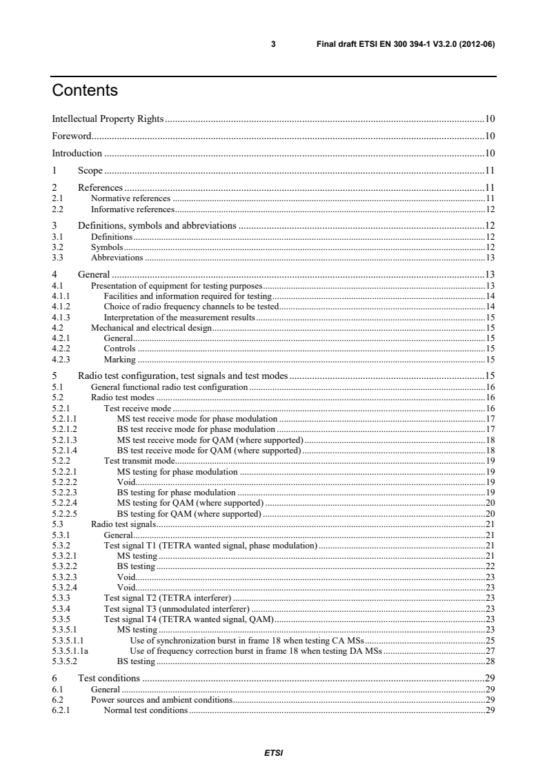
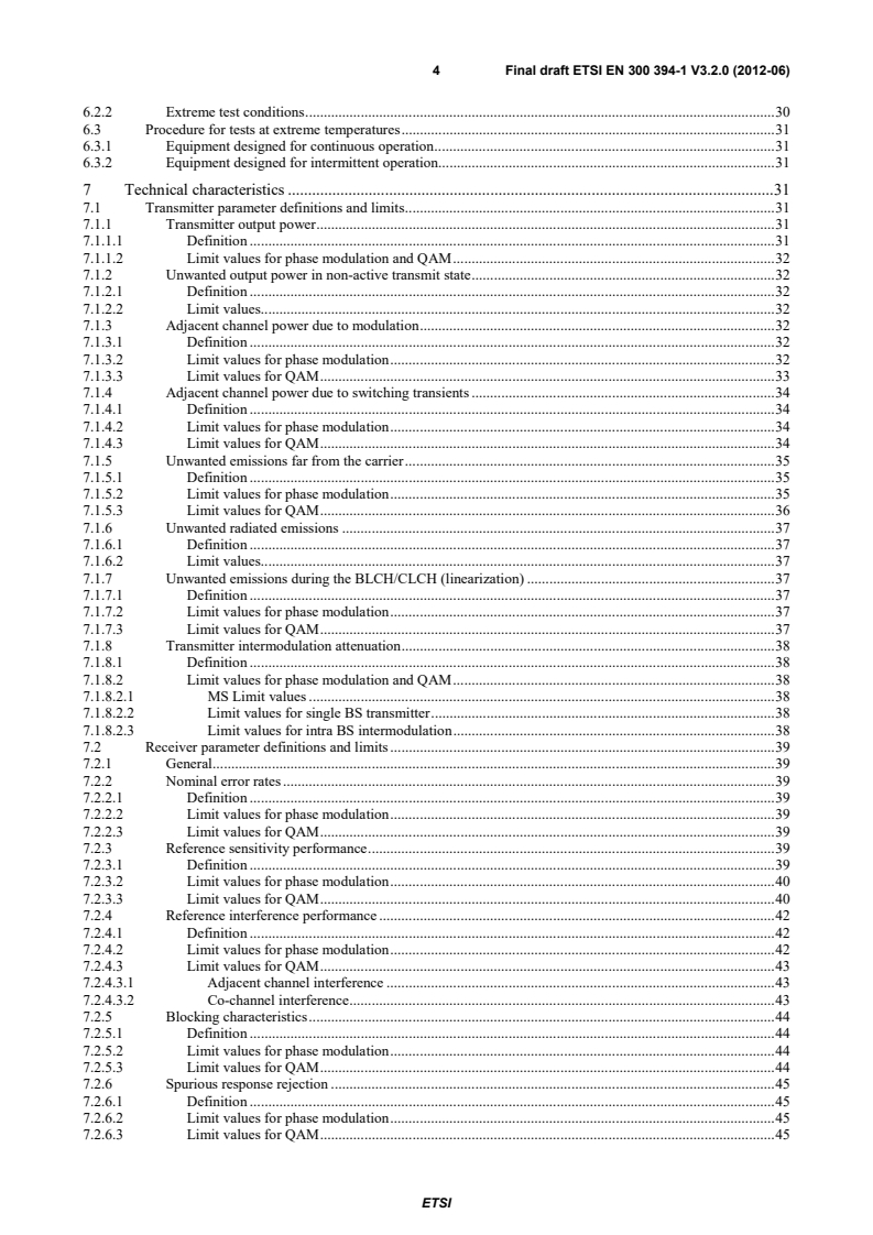
en_30039401v030200o - Terrestrial Trunked Radio (TETRA); Conformance testing specification; Part 1: Radio
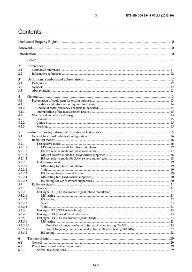
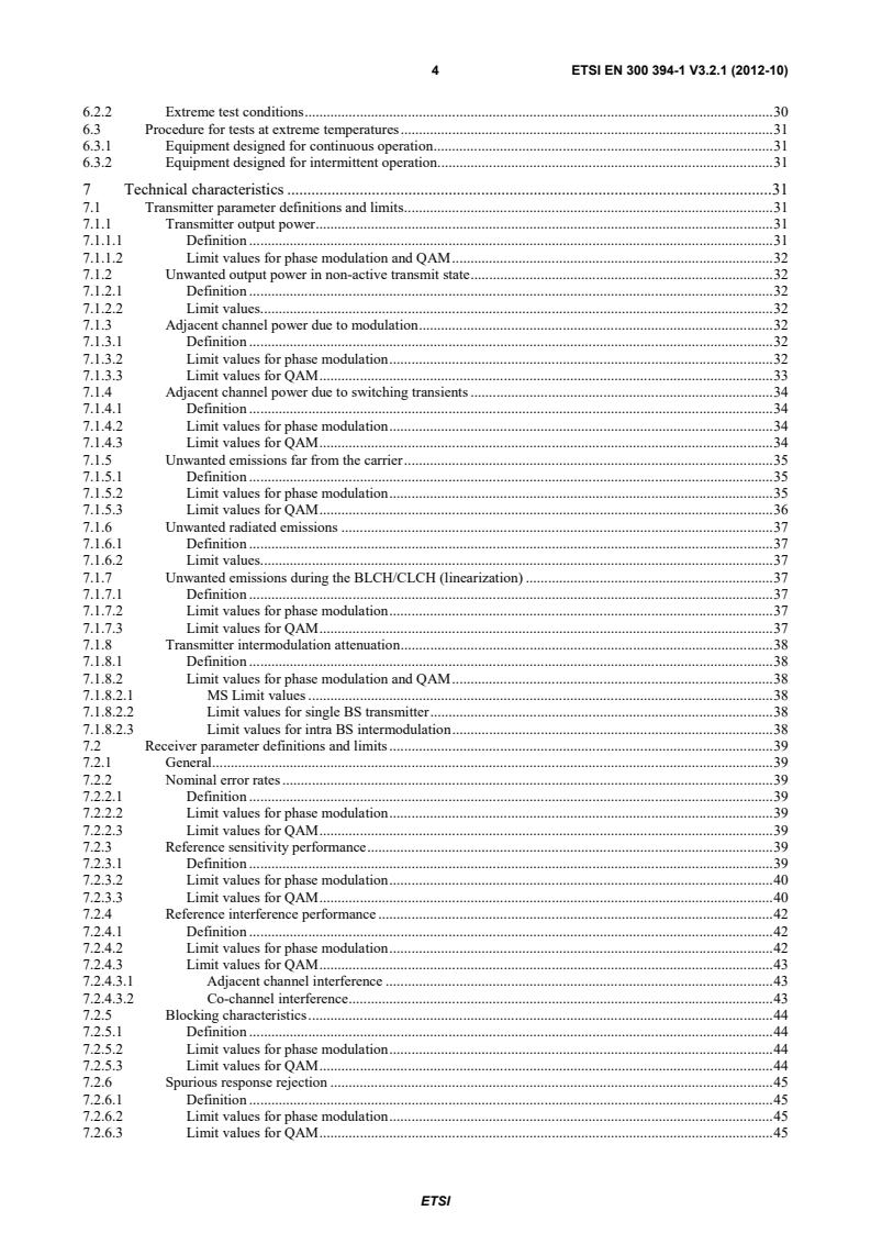
ETSI EN 300 394-1 V3.2.1 (2012-10) - Terrestrial Trunked Radio (TETRA); Conformance testing specification; Part 1: Radio

SIST EN 300 394-1 V3.2.1:2012 is the SIST adoption of the ETSI conformance testing specification for Terrestrial Trunked Radio (TETRA) radio equipment. It defines minimum radio characteristics and type-test methods for TETRA Voice plus Data (V+D) Base Stations (BS), Mobile Station (MS) equipment, and Direct Mode Operation (DMO) equipment in systems operating from 300 MHz to 1 GHz. The document is used by manufacturers, test laboratories, and approval teams that need a common basis for radio conformance testing.
What does SIST EN 300 394-1 V3.2.1:2012 specify?
SIST EN 300 394-1 V3.2.1:2012 specifies the radio part of TETRA conformance testing. The scope focuses on minimum technical characteristics, the radio test methods used for type testing, and the aim of achieving sufficient transmission and reception quality while limiting harmful interference.
The document applies to TETRA systems in the 300 MHz to 1 GHz range. The scope also points to annex F for specific DMO test methods.
The main structure is:
| Annex | What it covers |
|---|---|
| Annex A | TETRA receiver testing |
| Annex B | Radio test system functions |
| Annex C | TETRA Test Connector Interface (TTCI) |
| Annex D | RF test facility using RF loop back |
What are the key requirements of SIST EN 300 394-1 V3.2.1:2012?
SIST EN 300 394-1 V3.2.1:2012 is built around type testing under controlled radio conditions. In practice, the standard tells the applicant what must be provided, how to set up the test signal path, which channels to exercise, and how to judge transmitter, receiver, and combined RF performance.
Test setup and conditions
- Clause 4.1 requires equipment to be presented as production models or equivalent pre-production models, and each item must meet the requirements on all intended operating channels. This matters because approval should reflect the real product, not a special test sample.
- Clause 4.1.1 requires test access such as an antenna connector or a suitable jig or adapter, specific test modes, decoded data output, and for BS equipment a trigger signal for uplink synchronization. This gives the laboratory a repeatable way to control the test.
- Clause 4.1.2 limits the tested RF channels to selected channels from the lowest, highest, and middle parts of the operating band. This spreads testing across the band instead of checking only one convenient channel.
- Clause 5 defines the functional test configuration, test modes, and test signals, including T1, T2, T3, and T4. T1 and T4 are the wanted signals, T2 is the interferer, and T3 is an unmodulated interferer.
- Clause 6 sets normal and extreme test conditions for temperature, humidity, and power source. This is what makes test results comparable between labs and shows how equipment behaves outside room conditions.
Transmitter, receiver, and combined RF limits
- Clause 7.1 covers transmitter limits such as output power, unwanted output power in the non-active state, adjacent channel power, far-out unwanted emissions, radiated emissions, and intermodulation attenuation. These are the main checks for spectral cleanliness and output level.
- Clause 7.2 covers receiver performance such as nominal error rates, reference sensitivity, interference performance, blocking, spurious response rejection, intermodulation response rejection, and unwanted emissions. These tests show how well BS and MS receivers keep working in weak or disturbed conditions.
- Clause 7.3 covers combined transmitter/receiver behavior, including modulation accuracy, carrier frequency accuracy, MS synchronization burst acquisition, MS frame alignment, and MS link control. These tests matter for network access, stability, and correct timing.
- Clauses 8 to 10 give the measurement methods for those limits. The document pairs each limit with a test arrangement so the same performance is checked the same way.
- Clause 11 defines measurement uncertainty and how to interpret results. The measured value, together with uncertainty, is what is used to decide conformity.
What terms does SIST EN 300 394-1 V3.2.1:2012 define?
- Base Station (BS) - The fixed TETRA station that provides radio coverage and is tested for transmitter and receiver performance.
- Mobile Station (MS) - The TETRA user equipment or terminal tested for radio performance across the declared receive and transmit bands.
- Direct Mode Operation (DMO) - TETRA operation where terminals communicate directly, and specific test methods are referenced for DMO equipment.
- TETRA Test Connector Interface (TTCI) - The interface used to exchange decoded test data between the equipment and the test system, either physically or through an RF loop back arrangement.
- TETRA System Simulator (TSS) - The test-side system that emulates TETRA signalling and call setup during loopback and conformance tests.
- T1 Test Signal - The radio test signal used for phase modulation receiver testing and loopback scenarios.
- T4 Test Signal - The corresponding wanted signal used when QAM is supported.
Who uses SIST EN 300 394-1 V3.2.1:2012?
SIST EN 300 394-1 V3.2.1:2012 is used by TETRA equipment manufacturers, test laboratories, and conformity assessment teams. They use it to define test setups, verify radio performance, and document type-test results for BS, MS, and DMO-related equipment.
It is also relevant for quality managers, certification staff, and buyers who need to confirm that a product has been assessed against the same radio test methods and limits across a TETRA project or procurement.
What changed in SIST EN 300 394-1 V3.2.1:2012 from the previous edition?
SIST EN 300 394-1 V3.2.1:2012 adds Direct Access and multislot receiver testing in addition to the earlier Release 2 tests, and it is aligned with EN 300 392-2 [1].
Which standards are used with SIST EN 300 394-1 V3.2.1:2012?
- ETSI EN 300 392-2 / ETSI TS 100 392-2 - The TETRA V+D air interface reference used throughout the measurements and definitions.
- ITU-T Recommendation O.153 - Provides the basic error-performance reference used for receiver test sequences and sample-size rules.
- ETSI EN 300 113-1 - Supports the general approach to technical characteristics and methods of measurement for radio equipment.
- ITU-T Recommendation V.1 - Defines notation used for binary symbols and two-condition code references.
- ISO 2110:1989 - Defines the 25-pole connector used for the TTCI.
- ETSI EN 300 395-4 - Provides TETRA full-rate speech codec conformance testing.
- ETSI EN 300 396-2 - Provides DMO radio aspects.
- ETSI EN 300 392-1 - Covers general network design.
- ETSI EN 300 392-7 - Covers security.
- ETSI ETS 300 392-11-22 and ETSI EN 300 392-12-22 - Cover DGNA supplementary services.
- ETSI EN 300 395-2 - Provides the TETRA codec reference used in codec-related testing.
What does the SIST EN 300 394-1 V3.2.1:2012 document contain?
SIST EN 300 394-1 V3.2.1:2012 contains test configurations, signal definitions, and detailed measurement methods for transmitter, receiver, and combined radio characteristics. It also includes uncertainty guidance so test reports can record the measurement margin alongside the measured value.
The annexes add the practical test infrastructure: receiver test tables, radio test system functions, TTCI layer definitions and messages, and RF loop back procedures with loopback scenarios and returned bit structures.
The body of the document is organized so laboratories can select channels, apply T1 or T4 signals, run normal or extreme condition tests, and compare results against the stated limits without inventing their own procedure.
Buy Documents
en_30039401v030200o - Terrestrial Trunked Radio (TETRA); Conformance testing specification; Part 1: Radio
ETSI EN 300 394-1 V3.2.1 (2012-10) - Terrestrial Trunked Radio (TETRA); Conformance testing specification; Part 1: Radio
Get Certified
Connect with accredited certification bodies for this standard

ANCE
Mexican certification and testing association.

Intertek Slovenia
Intertek testing, inspection, and certification services in Slovenia.

LNE (Laboratoire National de Métrologie et d'Essais)
French national laboratory for metrology and testing.
Sponsored listings
Frequently Asked Questions
SIST EN 300 394-1 V3.2.1:2012 is a standard published by the Slovenian Institute for Standardization (SIST). Its full title is "Terrestrial Trunked Radio (TETRA) - Conformance testing specification - Part 1: Radio". This standard covers: The present document specifies the minimum technical characteristics of TETRA Voice plus Data (V+D) Base Stations (BS) and Mobile Station (MS) equipment, and TETRA Direct Mode Operation (DMO) equipment, and the radio test methods used for type testing. Specific test methods for DMO equipment are defined in annex F of the present document. The purpose of these specifications is to provide a sufficient quality of radio transmission and reception for equipment operating in a TETRA system and to minimize harmful interference to other equipment. The present document is applicable to TETRA systems operating at radio frequencies in the range of 300 MHz to 1 GHz. These specifications do not necessarily include all the characteristics which may be required by a user of equipment, nor do they necessarily represent the optimum performance achievable.
The present document specifies the minimum technical characteristics of TETRA Voice plus Data (V+D) Base Stations (BS) and Mobile Station (MS) equipment, and TETRA Direct Mode Operation (DMO) equipment, and the radio test methods used for type testing. Specific test methods for DMO equipment are defined in annex F of the present document. The purpose of these specifications is to provide a sufficient quality of radio transmission and reception for equipment operating in a TETRA system and to minimize harmful interference to other equipment. The present document is applicable to TETRA systems operating at radio frequencies in the range of 300 MHz to 1 GHz. These specifications do not necessarily include all the characteristics which may be required by a user of equipment, nor do they necessarily represent the optimum performance achievable.
SIST EN 300 394-1 V3.2.1:2012 is classified under the following ICS (International Classification for Standards) categories: 33.070.10 - Terrestrial Trunked Radio (TETRA). The ICS classification helps identify the subject area and facilitates finding related standards.
SIST EN 300 394-1 V3.2.1:2012 is available in PDF format for immediate download after purchase. The document can be added to your cart and obtained through the secure checkout process. Digital delivery ensures instant access to the complete standard document.
Standards Content (Sample)
Final draft ETSI EN 300 394-1 V3.2.0 (2012-06)
European Standard
Terrestrial Trunked Radio (TETRA);
Conformance testing specification;
Part 1: Radio
2 Final draft ETSI EN 300 394-1 V3.2.0 (2012-06)
Reference
REN/TETRA-03201
Keywords
DMO, testing, TETRA, V+D
ETSI
650 Route des Lucioles
F-06921 Sophia Antipolis Cedex - FRANCE
Tel.: +33 4 92 94 42 00 Fax: +33 4 93 65 47 16
Siret N° 348 623 562 00017 - NAF 742 C
Association à but non lucratif enregistrée à la
Sous-Préfecture de Grasse (06) N° 7803/88
Important notice
Individual copies of the present document can be downloaded from:
http://www.etsi.org
The present document may be made available in more than one electronic version or in print. In any case of existing or
perceived difference in contents between such versions, the reference version is the Portable Document Format (PDF).
In case of dispute, the reference shall be the printing on ETSI printers of the PDF version kept on a specific network drive
within ETSI Secretariat.
Users of the present document should be aware that the document may be subject to revision or change of status.
Information on the current status of this and other ETSI documents is available at
http://portal.etsi.org/tb/status/status.asp
If you find errors in the present document, please send your comment to one of the following services:
http://portal.etsi.org/chaircor/ETSI_support.asp
Copyright Notification
No part may be reproduced except as authorized by written permission.
The copyright and the foregoing restriction extend to reproduction in all media.
© European Telecommunications Standards Institute 2012.
All rights reserved.
TM TM TM
DECT , PLUGTESTS , UMTS and the ETSI logo are Trade Marks of ETSI registered for the benefit of its Members.
TM
3GPP and LTE™ are Trade Marks of ETSI registered for the benefit of its Members and
of the 3GPP Organizational Partners.
GSM® and the GSM logo are Trade Marks registered and owned by the GSM Association.
ETSI
3 Final draft ETSI EN 300 394-1 V3.2.0 (2012-06)
Contents
Intellectual Property Rights . 10
Foreword . 10
Introduction . 10
1 Scope . 11
2 References . 11
2.1 Normative references . 11
2.2 Informative references . 12
3 Definitions, symbols and abbreviations . 12
3.1 Definitions . 12
3.2 Symbols . 12
3.3 Abbreviations . 13
4 General . 13
4.1 Presentation of equipment for testing purposes . 13
4.1.1 Facilities and information required for testing . 14
4.1.2 Choice of radio frequency channels to be tested . 14
4.1.3 Interpretation of the measurement results . 15
4.2 Mechanical and electrical design . 15
4.2.1 General . 15
4.2.2 Controls . 15
4.2.3 Marking . 15
5 Radio test configuration, test signals and test modes . 15
5.1 General functional radio test configuration . 16
5.2 Radio test modes . 16
5.2.1 Test receive mode . 16
5.2.1.1 MS test receive mode for phase modulation . 17
5.2.1.2 BS test receive mode for phase modulation . 17
5.2.1.3 MS test receive mode for QAM (where supported) . 18
5.2.1.4 BS test receive mode for QAM (where supported) . 18
5.2.2 Test transmit mode. 19
5.2.2.1 MS testing for phase modulation . 19
5.2.2.2 Void. 19
5.2.2.3 BS testing for phase modulation . 19
5.2.2.4 MS testing for QAM (where supported) . 20
5.2.2.5 BS testing for QAM (where supported) . 20
5.3 Radio test signals . 21
5.3.1 General . 21
5.3.2 Test signal T1 (TETRA wanted signal, phase modulation) . 21
5.3.2.1 MS testing . 21
5.3.2.2 BS testing . 22
5.3.2.3 Void. 23
5.3.2.4 Void. 23
5.3.3 Test signal T2 (TETRA interferer) . 23
5.3.4 Test signal T3 (unmodulated interferer) . 23
5.3.5 Test signal T4 (TETRA wanted signal, QAM) . 23
5.3.5.1 MS testing . 23
5.3.5.1.1 Use of synchronization burst in frame 18 when testing CA MSs . 25
5.3.5.1.1a Use of frequency correction burst in frame 18 when testing DA MSs . 27
5.3.5.2 BS testing . 28
6 Test conditions . 29
6.1 General . 29
6.2 Power sources and ambient conditions . 29
6.2.1 Normal test conditions . 29
ETSI
4 Final draft ETSI EN 300 394-1 V3.2.0 (2012-06)
6.2.2 Extreme test conditions . 30
6.3 Procedure for tests at extreme temperatures . 31
6.3.1 Equipment designed for continuous operation . 31
6.3.2 Equipment designed for intermittent operation. 31
7 Technical characteristics . 31
7.1 Transmitter parameter definitions and limits . 31
7.1.1 Transmitter output power . 31
7.1.1.1 Definition . 31
7.1.1.2 Limit values for phase modulation and QAM . 32
7.1.2 Unwanted output power in non-active transmit state . 32
7.1.2.1 Definition . 32
7.1.2.2 Limit values. 32
7.1.3 Adjacent channel power due to modulation . 32
7.1.3.1 Definition . 32
7.1.3.2 Limit values for phase modulation . 32
7.1.3.3 Limit values for QAM . 33
7.1.4 Adjacent channel power due to switching transients . 34
7.1.4.1 Definition . 34
7.1.4.2 Limit values for phase modulation . 34
7.1.4.3 Limit values for QAM . 34
7.1.5 Unwanted emissions far from the carrier . 35
7.1.5.1 Definition . 35
7.1.5.2 Limit values for phase modulation . 35
7.1.5.3 Limit values for QAM . 36
7.1.6 Unwanted radiated emissions . 37
7.1.6.1 Definition . 37
7.1.6.2 Limit values. 37
7.1.7 Unwanted emissions during the BLCH/CLCH (linearization) . 37
7.1.7.1 Definition . 37
7.1.7.2 Limit values for phase modulation . 37
7.1.7.3 Limit values for QAM . 37
7.1.8 Transmitter intermodulation attenuation . 38
7.1.8.1 Definition . 38
7.1.8.2 Limit values for phase modulation and QAM . 38
7.1.8.2.1 MS Limit values . 38
7.1.8.2.2 Limit values for single BS transmitter . 38
7.1.8.2.3 Limit values for intra BS intermodulation . 38
7.2 Receiver parameter definitions and limits . 39
7.2.1 General . 39
7.2.2 Nominal error rates . 39
7.2.2.1 Definition . 39
7.2.2.2 Limit values for phase modulation . 39
7.2.2.3 Limit values for QAM . 39
7.2.3 Reference sensitivity performance . 39
7.2.3.1 Definition . 39
7.2.3.2 Limit values for phase modulation . 40
7.2.3.3 Limit values for QAM . 40
7.2.4 Reference interference performance . 42
7.2.4.1 Definition . 42
7.2.4.2 Limit values for phase modulation . 42
7.2.4.3 Limit values for QAM . 43
7.2.4.3.1 Adjacent channel interference . 43
7.2.4.3.2 Co-channel interference . 43
7.2.5 Blocking characteristics . 44
7.2.5.1 Definition . 44
7.2.5.2 Limit values for phase modulation . 44
7.2.5.3 Limit values for QAM . 44
7.2.6 Spurious response rejection . 45
7.2.6.1 Definition . 45
7.2.6.2 Limit values for phase modulation . 45
7.2.6.3 Limit values for QAM . 45
ETSI
5 Final draft ETSI EN 300 394-1 V3.2.0 (2012-06)
7.2.7 Intermodulation response rejection . 46
7.2.7.1 Definition . 46
7.2.7.2 Limit values. 46
7.2.8 Unwanted conducted emissions . 47
7.2.8.1 Definition . 47
7.2.8.2 Limit values. 47
7.2.9 Unwanted radiated emissions . 47
7.2.9.1 Definition . 47
7.2.9.2 Limit values. 47
7.3 Transmitter/receiver parameter definitions and limits . 47
7.3.1 Modulation accuracy. 47
7.3.1.1 Definition . 47
7.3.1.2 Limit values for phase modulation . 47
7.3.1.3 Limit values for QAM . 47
7.3.2 Carrier frequency accuracy . 48
7.3.2.1 Definition . 48
7.3.2.2 Limit values. 48
7.3.3 MS receiver performance for synchronization burst acquisition . 48
7.3.3.1 Definition for phase modulation . 48
7.3.3.2 Limit values for phase modulation . 48
7.3.3.3 Definition for QAM modulation . 48
7.3.3.4 Limit values for QAM modulation . 48
7.3.4 MS Frame alignment performance . 49
7.3.4.1 Definition . 49
7.3.4.2 Limit values. 49
7.3.5 MS link control . 49
7.3.5.1 Definition . 49
7.3.5.2 Limit values. 49
8 Methods of measurement for transmitter parameters . 50
8.1 Transmitter output power . 50
8.1.1 Transmitter output power for phase modulation . 50
8.1.1.1 MS transmitter output power for phase modulation . 50
8.1.1.2 BS transmitter output power for phase modulation . 51
8.1.2 Transmitter output power for QAM . 52
8.1.2.1 MS transmitter output power for QAM . 52
8.1.2.2 BS transmitter output power for QAM. 52
8.2 Unwanted output power in non active transmit state . 53
8.3 Adjacent channel power due to modulation . 53
8.4 Adjacent channel power due to switching transients . 54
8.5 Unwanted emissions far from the carrier . 54
8.6 Unwanted radiated emissions . 56
8.7 Unwanted emissions during the BLCH/CLCH and BLCH-Q/CLCH-Q (linearization) . 56
8.7.1 MS unwanted emissions during the CLCH (linearization) . 56
8.7.2 BS unwanted emissions during the BLCH (linearization) . 57
8.7.3 MS unwanted emissions during the CLCH-Q (linearization) . 57
8.7.4 BS unwanted emissions during the BLCH-Q (linearization) . 57
8.8 Transmitter intermodulation attenuation . 58
8.8.1 MS Transmitter intermodulation attenuation . 58
8.8.2 BS Transmitter intermodulation attenuation . 58
8.8.3 Intra BS transmitter intermodulation attenuation . 58
9 Methods of measurement for receiver parameters . 59
9.1 General . 59
9.2 Nominal error rates for phase modulation . 59
9.2.1 MS nominal error rate . 59
9.2.2 BS nominal error rate . 59
9.3 Reference sensitivity performance . 59
9.3.1 MS reference sensitivity performance for phase modulation . 59
9.3.2 BS reference sensitivity performance for phase modulation . 60
9.3.3 MS reference sensitivity performance for QAM . 60
9.3.4 BS reference sensitivity performance for QAM . 60
ETSI
6 Final draft ETSI EN 300 394-1 V3.2.0 (2012-06)
9.3.5 PUEM performance . 60
9.4 Reference interference performance . 61
9.4.1 MS reference interference performance for phase modulation . 61
9.4.2 BS reference interference performance for phase modulation . 61
9.4.3 MS reference interference performance for QAM . 61
9.4.4 BS reference interference performance for QAM . 62
9.5 Blocking characteristics . 62
9.5.1 MS blocking for phase modulation . 62
9.5.2 BS blocking for phase modulation . 63
9.5.3 MS blocking for QAM . 63
9.5.4 BS blocking for QAM. 63
9.6 Spurious response rejection . 63
9.6.1 Phase Modulation . 63
9.6.2 QAM . 64
9.7 Intermodulation response rejection . 64
9.7.1 MS intermodulation response rejection for phase modulation . 64
9.7.2 BS intermodulation response rejection for phase modulation . 64
9.7.3 MS intermodulation response rejection for QAM . 65
9.7.4 BS intermodulation response rejection for QAM . 65
9.8 Unwanted emissions . 65
9.9 Unwanted radiated emissions . 66
10 Methods of measurement for transmitter/receiver parameters . 66
10.1 Modulation accuracy . 66
10.1.1 MS modulation accuracy for phase modulation. 66
10.1.2 BS modulation accuracy for phase modulation . 67
10.1.3 Vector error magnitude at symbol time for phase modulation . 67
10.1.4 MS modulation accuracy for QAM . 67
10.1.5 BS modulation accuracy for QAM . 67
10.1.6 Vector error magnitude at symbol time for QAM . 67
10.2 Carrier frequency accuracy. 68
10.2.1 MS carrier frequency accuracy for phase modulation . 68
10.2.2 BS carrier frequency accuracy for phase modulation . 68
10.2.3 MS carrier frequency accuracy for QAM . 69
10.2.4 BS carrier frequency accuracy for QAM . 69
10.3 MS receiver performance for synchronization acquisition . 70
10.3.1 CA MS receiver performance for synchronization burst acquisition . 70
10.3.2 DA MS receiver performance for frequency correction burst acquisition . 70
10.4 MS Frame alignment performance . 70
10.5 MS link control . 71
11 Measurement uncertainty . 72
11.1 Transmitter . 72
11.2 Receiver . 76
11.3 Transmitter/receiver parameter definitions and limits . 77
11.4 Interpretation of measurement results . 78
Annex A (normative): TETRA receiver testing . 79
A.1 Frequencies of spurious response . 79
A.2 Test cases and test conditions for BS and MS receivers . 79
A.3 Test signal T1/T4, content of BSCH, BSCH-Q/T, BNCH/T and BNCH-Q/T . 108
Annex B (normative): Radio test system functions . 115
B.1 Test transmitter and receiver . 115
B.1.1 General . 115
B.1.2 Sampling system . 115
B.1.2.1 General . 115
B.1.2.2 TETRA filter . 115
B.1.2.3 Adjacent channel power measurements . 116
B.1.2.4 Modulation accuracy measurements . 116
ETSI
7 Final draft ETSI EN 300 394-1 V3.2.0 (2012-06)
B.1.2.5 Measurement of unwanted output power in the non-active transmit state . 116
B.1.3 Spectrum analyser . 116
B.1.4 Error rate tester . 116
B.1.5 Test signal requirements . 117
B.1.5.1 On channel test signal T1 . 117
B.1.5.2 Interfering test signal T2 . 117
B.1.5.2.1 Phase Modulated . 117
B.1.5.2.2 QAM Modulated . 117
B.1.5.3 Interfering test signal T3 . 117
B.1.5.4 On channel test signal T4 . 118
B.1.6 Propagation simulators . 118
B.1.7 Timing measurement unit . 118
B.1.8 Passive test system components . 118
B.1.9 Test system controller . 118
Annex C (normative): TETRA Test Connector Interface (TTCI) . 119
C.1 General . 119
C.2 Formal aspects . 119
C.3 TTCI, layer 1 . 119
C.3.1 Mechanical and electrical characteristics . 119
C.3.2 Transmission and reception characteristics . 120
C.4 TTCI, Layer 2 . 120
C.4.1 General structure . 120
C.4.2 Frame structure . 120
C.4.3 Flow of I-frames on layer 2 . 121
C.4.3.1 Transmission of frames . 121
C.4.3.2 Reception of frames . 121
C.4.3.3 Parameters on layer 2 . 122
C.5 TTCI, Layer 3 . 122
C.5.1 Message structure . 122
C.5.2 Definitions of the messages . 122
C.5.2.1 DATO . 122
C.5.2.1.1 Test equipment error handling . 124
C.5.2.2 Bi-directional operation of the TTCI . 124
C.5.2.3 Codec conformance testing . 125
C.5.2.4 ST indicator . 125
C.6 Control of MS/BS . 126
C.6.1 Manual intervention of MS/BS . 126
C.6.2 Bi-directional operation of the test interface . 126
C.6.3 MS controlled by T1. 126
C.7 Characteristics of the interface . 126
C.7.1 Mechanical characteristics of the interface. 126
C.7.2 Electric characteristics of the interface . 126
C.8 Codec conformance testing using the TTCI . 127
C.8.1 Codec conformance test methodology using the TTCI .
...
European Standard
Terrestrial Trunked Radio (TETRA);
Conformance testing specification;
Part 1: Radio
2 ETSI EN 300 394-1 V3.2.1 (2012-10)
Reference
REN/TETRA-03201
Keywords
DMO, testing, TETRA, V+D
ETSI
650 Route des Lucioles
F-06921 Sophia Antipolis Cedex - FRANCE
Tel.: +33 4 92 94 42 00 Fax: +33 4 93 65 47 16
Siret N° 348 623 562 00017 - NAF 742 C
Association à but non lucratif enregistrée à la
Sous-Préfecture de Grasse (06) N° 7803/88
Important notice
Individual copies of the present document can be downloaded from:
http://www.etsi.org
The present document may be made available in more than one electronic version or in print. In any case of existing or
perceived difference in contents between such versions, the reference version is the Portable Document Format (PDF).
In case of dispute, the reference shall be the printing on ETSI printers of the PDF version kept on a specific network drive
within ETSI Secretariat.
Users of the present document should be aware that the document may be subject to revision or change of status.
Information on the current status of this and other ETSI documents is available at
http://portal.etsi.org/tb/status/status.asp
If you find errors in the present document, please send your comment to one of the following services:
http://portal.etsi.org/chaircor/ETSI_support.asp
Copyright Notification
No part may be reproduced except as authorized by written permission.
The copyright and the foregoing restriction extend to reproduction in all media.
© European Telecommunications Standards Institute 2012.
All rights reserved.
TM TM TM
DECT , PLUGTESTS , UMTS and the ETSI logo are Trade Marks of ETSI registered for the benefit of its Members.
TM
3GPP and LTE™ are Trade Marks of ETSI registered for the benefit of its Members and
of the 3GPP Organizational Partners.
GSM® and the GSM logo are Trade Marks registered and owned by the GSM Association.
ETSI
3 ETSI EN 300 394-1 V3.2.1 (2012-10)
Contents
Intellectual Property Rights . 10
Foreword . 10
Introduction . 10
1 Scope . 11
2 References . 11
2.1 Normative references . 11
2.2 Informative references . 12
3 Definitions, symbols and abbreviations . 12
3.1 Definitions . 12
3.2 Symbols . 12
3.3 Abbreviations . 13
4 General . 13
4.1 Presentation of equipment for testing purposes . 13
4.1.1 Facilities and information required for testing . 14
4.1.2 Choice of radio frequency channels to be tested . 14
4.1.3 Interpretation of the measurement results . 15
4.2 Mechanical and electrical design . 15
4.2.1 General . 15
4.2.2 Controls . 15
4.2.3 Marking . 15
5 Radio test configuration, test signals and test modes . 15
5.1 General functional radio test configuration . 16
5.2 Radio test modes . 16
5.2.1 Test receive mode . 16
5.2.1.1 MS test receive mode for phase modulation . 17
5.2.1.2 BS test receive mode for phase modulation . 17
5.2.1.3 MS test receive mode for QAM (where supported) . 18
5.2.1.4 BS test receive mode for QAM (where supported) . 18
5.2.2 Test transmit mode. 19
5.2.2.1 MS testing for phase modulation . 19
5.2.2.2 Void. 19
5.2.2.3 BS testing for phase modulation . 19
5.2.2.4 MS testing for QAM (where supported) . 20
5.2.2.5 BS testing for QAM (where supported) . 20
5.3 Radio test signals . 21
5.3.1 General . 21
5.3.2 Test signal T1 (TETRA wanted signal, phase modulation) . 21
5.3.2.1 MS testing . 21
5.3.2.2 BS testing . 22
5.3.2.3 Void. 23
5.3.2.4 Void. 23
5.3.3 Test signal T2 (TETRA interferer) . 23
5.3.4 Test signal T3 (unmodulated interferer) . 23
5.3.5 Test signal T4 (TETRA wanted signal, QAM) . 23
5.3.5.1 MS testing . 23
5.3.5.1.1 Use of synchronization burst in frame 18 when testing CA MSs . 25
5.3.5.1.1a Use of frequency correction burst in frame 18 when testing DA MSs . 27
5.3.5.2 BS testing . 28
6 Test conditions . 29
6.1 General . 29
6.2 Power sources and ambient conditions . 29
6.2.1 Normal test conditions . 29
ETSI
4 ETSI EN 300 394-1 V3.2.1 (2012-10)
6.2.2 Extreme test conditions . 30
6.3 Procedure for tests at extreme temperatures . 31
6.3.1 Equipment designed for continuous operation . 31
6.3.2 Equipment designed for intermittent operation. 31
7 Technical characteristics . 31
7.1 Transmitter parameter definitions and limits . 31
7.1.1 Transmitter output power . 31
7.1.1.1 Definition . 31
7.1.1.2 Limit values for phase modulation and QAM . 32
7.1.2 Unwanted output power in non-active transmit state . 32
7.1.2.1 Definition . 32
7.1.2.2 Limit values. 32
7.1.3 Adjacent channel power due to modulation . 32
7.1.3.1 Definition . 32
7.1.3.2 Limit values for phase modulation . 32
7.1.3.3 Limit values for QAM . 33
7.1.4 Adjacent channel power due to switching transients . 34
7.1.4.1 Definition . 34
7.1.4.2 Limit values for phase modulation . 34
7.1.4.3 Limit values for QAM . 34
7.1.5 Unwanted emissions far from the carrier . 35
7.1.5.1 Definition . 35
7.1.5.2 Limit values for phase modulation . 35
7.1.5.3 Limit values for QAM . 36
7.1.6 Unwanted radiated emissions . 37
7.1.6.1 Definition . 37
7.1.6.2 Limit values. 37
7.1.7 Unwanted emissions during the BLCH/CLCH (linearization) . 37
7.1.7.1 Definition . 37
7.1.7.2 Limit values for phase modulation . 37
7.1.7.3 Limit values for QAM . 37
7.1.8 Transmitter intermodulation attenuation . 38
7.1.8.1 Definition . 38
7.1.8.2 Limit values for phase modulation and QAM . 38
7.1.8.2.1 MS Limit values . 38
7.1.8.2.2 Limit values for single BS transmitter . 38
7.1.8.2.3 Limit values for intra BS intermodulation . 38
7.2 Receiver parameter definitions and limits . 39
7.2.1 General . 39
7.2.2 Nominal error rates . 39
7.2.2.1 Definition . 39
7.2.2.2 Limit values for phase modulation . 39
7.2.2.3 Limit values for QAM . 39
7.2.3 Reference sensitivity performance . 39
7.2.3.1 Definition . 39
7.2.3.2 Limit values for phase modulation . 40
7.2.3.3 Limit values for QAM . 40
7.2.4 Reference interference performance . 42
7.2.4.1 Definition . 42
7.2.4.2 Limit values for phase modulation . 42
7.2.4.3 Limit values for QAM . 43
7.2.4.3.1 Adjacent channel interference . 43
7.2.4.3.2 Co-channel interference . 43
7.2.5 Blocking characteristics . 44
7.2.5.1 Definition . 44
7.2.5.2 Limit values for phase modulation . 44
7.2.5.3 Limit values for QAM . 44
7.2.6 Spurious response rejection . 45
7.2.6.1 Definition . 45
7.2.6.2 Limit values for phase modulation . 45
7.2.6.3 Limit values for QAM . 45
ETSI
5 ETSI EN 300 394-1 V3.2.1 (2012-10)
7.2.7 Intermodulation response rejection . 46
7.2.7.1 Definition . 46
7.2.7.2 Limit values. 46
7.2.8 Unwanted conducted emissions . 47
7.2.8.1 Definition . 47
7.2.8.2 Limit values. 47
7.2.9 Unwanted radiated emissions . 47
7.2.9.1 Definition . 47
7.2.9.2 Limit values. 47
7.3 Transmitter/receiver parameter definitions and limits . 47
7.3.1 Modulation accuracy. 47
7.3.1.1 Definition . 47
7.3.1.2 Limit values for phase modulation . 47
7.3.1.3 Limit values for QAM . 47
7.3.2 Carrier frequency accuracy . 48
7.3.2.1 Definition . 48
7.3.2.2 Limit values. 48
7.3.3 MS receiver performance for synchronization burst acquisition . 48
7.3.3.1 Definition for phase modulation . 48
7.3.3.2 Limit values for phase modulation . 48
7.3.3.3 Definition for QAM modulation . 48
7.3.3.4 Limit values for QAM modulation . 48
7.3.4 MS Frame alignment performance . 49
7.3.4.1 Definition . 49
7.3.4.2 Limit values. 49
7.3.5 MS link control . 49
7.3.5.1 Definition . 49
7.3.5.2 Limit values. 49
8 Methods of measurement for transmitter parameters . 50
8.1 Transmitter output power . 50
8.1.1 Transmitter output power for phase modulation . 50
8.1.1.1 MS transmitter output power for phase modulation . 50
8.1.1.2 BS transmitter output power for phase modulation . 51
8.1.2 Transmitter output power for QAM . 52
8.1.2.1 MS transmitter output power for QAM . 52
8.1.2.2 BS transmitter output power for QAM. 53
8.2 Unwanted output power in non active transmit state . 53
8.3 Adjacent channel power due to modulation . 53
8.4 Adjacent channel power due to switching transients . 54
8.5 Unwanted emissions far from the carrier . 54
8.6 Unwanted radiated emissions . 56
8.7 Unwanted emissions during the BLCH/CLCH and BLCH-Q/CLCH-Q (linearization) . 56
8.7.1 MS unwanted emissions during the CLCH (linearization) . 56
8.7.2 BS unwanted emissions during the BLCH (linearization) . 57
8.7.3 MS unwanted emissions during the CLCH-Q (linearization) . 57
8.7.4 BS unwanted emissions during the BLCH-Q (linearization) . 57
8.8 Transmitter intermodulation attenuation . 58
8.8.1 MS Transmitter intermodulation attenuation . 58
8.8.2 BS Transmitter intermodulation attenuation . 58
8.8.3 Intra BS transmitter intermodulation attenuation . 58
9 Methods of measurement for receiver parameters . 59
9.1 General . 59
9.2 Nominal error rates for phase modulation . 59
9.2.1 MS nominal error rate . 59
9.2.2 BS nominal error rate . 59
9.3 Reference sensitivity performance . 59
9.3.1 MS reference sensitivity performance for phase modulation . 59
9.3.2 BS reference sensitivity performance for phase modulation . 60
9.3.3 MS reference sensitivity performance for QAM . 60
9.3.4 BS reference sensitivity performance for QAM . 60
ETSI
6 ETSI EN 300 394-1 V3.2.1 (2012-10)
9.3.5 PUEM performance . 60
9.4 Reference interference performance . 61
9.4.1 MS reference interference performance for phase modulation . 61
9.4.2 BS reference interference performance for phase modulation . 61
9.4.3 MS reference interference performance for QAM . 61
9.4.4 BS reference interference performance for QAM . 62
9.5 Blocking characteristics . 62
9.5.1 MS blocking for phase modulation . 62
9.5.2 BS blocking for phase modulation . 63
9.5.3 MS blocking for QAM . 63
9.5.4 BS blocking for QAM. 63
9.6 Spurious response rejection . 63
9.6.1 Phase Modulation . 63
9.6.2 QAM . 64
9.7 Intermodulation response rejection . 64
9.7.1 MS intermodulation response rejection for phase modulation . 64
9.7.2 BS intermodulation response rejection for phase modulation . 64
9.7.3 MS intermodulation response rejection for QAM . 65
9.7.4 BS intermodulation response rejection for QAM . 65
9.8 Unwanted emissions . 65
9.9 Unwanted radiated emissions . 66
10 Methods of measurement for transmitter/receiver parameters . 66
10.1 Modulation accuracy . 66
10.1.1 MS modulation accuracy for phase modulation. 66
10.1.2 BS modulation accuracy for phase modulation . 67
10.1.3 Vector error magnitude at symbol time for phase modulation . 67
10.1.4 MS modulation accuracy for QAM . 67
10.1.5 BS modulation accuracy for QAM . 67
10.1.6 Vector error magnitude at symbol time for QAM . 67
10.2 Carrier frequency accuracy. 68
10.2.1 MS carrier frequency accuracy for phase modulation . 68
10.2.2 BS carrier frequency accuracy for phase modulation . 68
10.2.3 MS carrier frequency accuracy for QAM . 69
10.2.4 BS carrier frequency accuracy for QAM . 69
10.3 MS receiver performance for synchronization acquisition . 70
10.3.1 CA MS receiver performance for synchronization burst acquisition . 70
10.3.2 DA MS receiver performance for frequency correction burst acquisition . 70
10.4 MS Frame alignment performance . 70
10.5 MS link control . 71
11 Measurement uncertainty . 72
11.1 Transmitter . 72
11.2 Receiver . 76
11.3 Transmitter/receiver parameter definitions and limits . 77
11.4 Interpretation of measurement results . 78
Annex A (normative): TETRA receiver testing . 79
A.1 Frequencies of spurious response . 79
A.2 Test cases and test conditions for BS and MS receivers . 79
A.3 Test signal T1/T4, content of BSCH, BSCH-Q/T, BNCH/T and BNCH-Q/T . 108
Annex B (normative): Radio test system functions . 115
B.1 Test transmitter and receiver . 115
B.1.1 General . 115
B.1.2 Sampling system . 115
B.1.2.1 General . 115
B.1.2.2 TETRA filter . 115
B.1.2.3 Adjacent channel power measurements . 116
B.1.2.4 Modulation accuracy measurements . 116
ETSI
7 ETSI EN 300 394-1 V3.2.1 (2012-10)
B.1.2.5 Measurement of unwanted output power in the non-active transmit state . 116
B.1.3 Spectrum analyser . 116
B.1.4 Error rate tester . 116
B.1.5 Test signal requirements . 117
B.1.5.1 On channel test signal T1 . 117
B.1.5.2 Interfering test signal T2 . 117
B.1.5.2.1 Phase Modulated . 117
B.1.5.2.2 QAM Modulated . 117
B.1.5.3 Interfering test signal T3 . 117
B.1.5.4 On channel test signal T4 . 118
B.1.6 Propagation simulators . 118
B.1.7 Timing measurement unit . 118
B.1.8 Passive test system components . 118
B.1.9 Test system controller . 118
Annex C (normative): TETRA Test Connector Interface (TTCI) . 119
C.1 General . 119
C.2 Formal aspects . 119
C.3 TTCI, layer 1 . 119
C.3.1 Mechanical and electrical characteristics . 119
C.3.2 Transmission and reception characteristics . 120
C.4 TTCI, Layer 2 . 120
C.4.1 General structure . 120
C.4.2 Frame structure . 120
C.4.3 Flow of I-frames on layer 2 . 121
C.4.3.1 Transmission of frames . 121
C.4.3.2 Reception of frames . 121
C.4.3.3 Parameters on layer 2 . 122
C.5 TTCI, Layer 3 . 122
C.5.1 Message structure . 122
C.5.2 Definitions of the messages . 122
C.5.2.1 DATO . 122
C.5.2.1.1 Test equipment error handling . 124
C.5.2.2 Bi-directional operation of the TTCI . 124
C.5.2.3 Codec conformance testing . 125
C.5.2.4 ST indicator . 125
C.6 Control of MS/BS . 126
C.6.1 Manual intervention of MS/BS . 126
C.6.2 Bi-directional operation of the test interface . 126
C.6.3 MS controlled by T1. 126
C.7 Characteristics of the interface . 126
C.7.1 Mechanical characteristics of the interface. 126
C.7.2 Electric characteristics of the interface . 126
C.8 Codec conformance testing using the TTCI . 127
C.8.1 Codec conformance test methodology using the TTCI . 127
Annex D (normative): RF test facility using RF loop back .
...
2003-01.Slovenski inštitut za standardizacijo. Razmnoževanje celote ali delov tega standarda ni dovoljeno.Prizemni snopovni radio (TETRA) - Specifikacija za preskušanje skladnosti - 1. del: RadioTerrestrial Trunked Radio (TETRA) - Conformance testing specification - Part 1: Radio33.070.10Prizemni snopovni radio (TETRA)Terrestrial Trunked Radio (TETRA)ICS:Ta slovenski standard je istoveten z:EN 300 394-1 Version 3.2.1SIST EN 300 394-1 V3.2.1:2012en01-december-2012SIST EN 300 394-1 V3.2.1:2012SLOVENSKI
STANDARD
European Standard SIST EN 300 394-1 V3.2.1:2012
ETSI ETSI EN 300 394-1 V3.2.1 (2012-10)2
Reference REN/TETRA-03201 Keywords DMO, testing, TETRA, V+D ETSI 650 Route des Lucioles F-06921 Sophia Antipolis Cedex - FRANCE
Tel.: +33 4 92 94 42 00
Fax: +33 4 93 65 47 16
Siret N° 348 623 562 00017 - NAF 742 C Association à but non lucratif enregistrée à la Sous-Préfecture de Grasse (06) N° 7803/88
Important notice Individual copies of the present document can be downloaded from: http://www.etsi.org The present document may be made available in more than one electronic version or in print. In any case of existing or perceived difference in contents between such versions, the reference version is the Portable Document Format (PDF). In case of dispute, the reference shall be the printing on ETSI printers of the PDF version kept on a specific network drive within ETSI Secretariat. Users of the present document should be aware that the document may be subject to revision or change of status. Information on the current status of this and other ETSI documents is available at http://portal.etsi.org/tb/status/status.asp If you find errors in the present document, please send your comment to one of the following services: http://portal.etsi.org/chaircor/ETSI_support.asp Copyright Notification No part may be reproduced except as authorized by written permission. The copyright and the foregoing restriction extend to reproduction in all media.
© European Telecommunications Standards Institute 2012. All rights reserved.
DECTTM, PLUGTESTSTM, UMTSTM and the ETSI logo are Trade Marks of ETSI registered for the benefit of its Members. 3GPPTM and LTE™ are Trade Marks of ETSI registered for the benefit of its Members and of the 3GPP Organizational Partners. GSM® and the GSM logo are Trade Marks registered and owned by the GSM Association. SIST EN 300 394-1 V3.2.1:2012
ETSI ETSI EN 300 394-1 V3.2.1 (2012-10)3 Contents Intellectual Property Rights . 10 Foreword . 10 Introduction . 10 1 Scope . 11 2 References . 11 2.1 Normative references . 11 2.2 Informative references . 12 3 Definitions, symbols and abbreviations . 12 3.1 Definitions . 12 3.2 Symbols . 12 3.3 Abbreviations . 13 4 General . 13 4.1 Presentation of equipment for testing purposes . 13 4.1.1 Facilities and information required for testing . 14 4.1.2 Choice of radio frequency channels to be tested . 14 4.1.3 Interpretation of the measurement results . 15 4.2 Mechanical and electrical design . 15 4.2.1 General . 15 4.2.2 Controls . 15 4.2.3 Marking . 15 5 Radio test configuration, test signals and test modes . 15 5.1 General functional radio test configuration . 16 5.2 Radio test modes . 16 5.2.1 Test receive mode . 16 5.2.1.1 MS test receive mode for phase modulation . 17 5.2.1.2 BS test receive mode for phase modulation . 17 5.2.1.3 MS test receive mode for QAM (where supported) . 18 5.2.1.4 BS test receive mode for QAM (where supported) . 18 5.2.2 Test transmit mode. 19 5.2.2.1 MS testing for phase modulation . 19 5.2.2.2 Void. 19 5.2.2.3 BS testing for phase modulation . 19 5.2.2.4 MS testing for QAM (where supported) . 20 5.2.2.5 BS testing for QAM (where supported) . 20 5.3 Radio test signals . 21 5.3.1 General . 21 5.3.2 Test signal T1 (TETRA wanted signal, phase modulation) . 21 5.3.2.1 MS testing . 21 5.3.2.2 BS testing . 22 5.3.2.3 Void. 23 5.3.2.4 Void. 23 5.3.3 Test signal T2 (TETRA interferer) . 23 5.3.4 Test signal T3 (unmodulated interferer) . 23 5.3.5 Test signal T4 (TETRA wanted signal, QAM) . 23 5.3.5.1 MS testing . 23 5.3.5.1.1 Use of synchronization burst in frame 18 when testing CA MSs . 25 5.3.5.1.1a Use of frequency correction burst in frame 18 when testing DA MSs . 27 5.3.5.2 BS testing . 28 6 Test conditions . 29 6.1 General . 29 6.2 Power sources and ambient conditions . 29 6.2.1 Normal test conditions . 29 SIST EN 300 394-1 V3.2.1:2012
ETSI ETSI EN 300 394-1 V3.2.1 (2012-10)4 6.2.2 Extreme test conditions . 30 6.3 Procedure for tests at extreme temperatures . 31 6.3.1 Equipment designed for continuous operation . 31 6.3.2 Equipment designed for intermittent operation. 31 7 Technical characteristics . 31 7.1 Transmitter parameter definitions and limits . 31 7.1.1 Transmitter output power . 31 7.1.1.1 Definition . 31 7.1.1.2 Limit values for phase modulation and QAM . 32 7.1.2 Unwanted output power in non-active transmit state . 32 7.1.2.1 Definition . 32 7.1.2.2 Limit values. 32 7.1.3 Adjacent channel power due to modulation . 32 7.1.3.1 Definition . 32 7.1.3.2 Limit values for phase modulation . 32 7.1.3.3 Limit values for QAM . 33 7.1.4 Adjacent channel power due to switching transients . 34 7.1.4.1 Definition . 34 7.1.4.2 Limit values for phase modulation . 34 7.1.4.3 Limit values for QAM . 34 7.1.5 Unwanted emissions far from the carrier . 35 7.1.5.1 Definition . 35 7.1.5.2 Limit values for phase modulation . 35 7.1.5.3 Limit values for QAM . 36 7.1.6 Unwanted radiated emissions . 37 7.1.6.1 Definition . 37 7.1.6.2 Limit values. 37 7.1.7 Unwanted emissions during the BLCH/CLCH (linearization) . 37 7.1.7.1 Definition . 37 7.1.7.2 Limit values for phase modulation . 37 7.1.7.3 Limit values for QAM . 37 7.1.8 Transmitter intermodulation attenuation . 38 7.1.8.1 Definition . 38 7.1.8.2 Limit values for phase modulation and QAM . 38 7.1.8.2.1 MS Limit values . 38 7.1.8.2.2 Limit values for single BS transmitter . 38 7.1.8.2.3 Limit values for intra BS intermodulation . 38 7.2 Receiver parameter definitions and limits . 39 7.2.1 General . 39 7.2.2 Nominal error rates . 39 7.2.2.1 Definition . 39 7.2.2.2 Limit values for phase modulation . 39 7.2.2.3 Limit values for QAM . 39 7.2.3 Reference sensitivity performance . 39 7.2.3.1 Definition . 39 7.2.3.2 Limit values for phase modulation . 40 7.2.3.3 Limit values for QAM . 40 7.2.4 Reference interference performance . 42 7.2.4.1 Definition . 42 7.2.4.2 Limit values for phase modulation . 42 7.2.4.3 Limit values for QAM . 43 7.2.4.3.1 Adjacent channel interference . 43 7.2.4.3.2 Co-channel interference . 43 7.2.5 Blocking characteristics . 44 7.2.5.1 Definition . 44 7.2.5.2 Limit values for phase modulation . 44 7.2.5.3 Limit values for QAM . 44 7.2.6 Spurious response rejection . 45 7.2.6.1 Definition . 45 7.2.6.2 Limit values for phase modulation . 45 7.2.6.3 Limit values for QAM . 45 SIST EN 300 394-1 V3.2.1:2012
ETSI ETSI EN 300 394-1 V3.2.1 (2012-10)5 7.2.7 Intermodulation response rejection . 46 7.2.7.1 Definition . 46 7.2.7.2 Limit values. 46 7.2.8 Unwanted conducted emissions . 47 7.2.8.1 Definition . 47 7.2.8.2 Limit values. 47 7.2.9 Unwanted radiated emissions . 47 7.2.9.1 Definition . 47 7.2.9.2 Limit values. 47 7.3 Transmitter/receiver parameter definitions and limits . 47 7.3.1 Modulation accuracy. 47 7.3.1.1 Definition . 47 7.3.1.2 Limit values for phase modulation . 47 7.3.1.3 Limit values for QAM . 47 7.3.2 Carrier frequency accuracy . 48 7.3.2.1 Definition . 48 7.3.2.2 Limit values. 48 7.3.3 MS receiver performance for synchronization burst acquisition . 48 7.3.3.1 Definition for phase modulation . 48 7.3.3.2 Limit values for phase modulation . 48 7.3.3.3 Definition for QAM modulation . 48 7.3.3.4 Limit values for QAM modulation . 48 7.3.4 MS Frame alignment performance . 49 7.3.4.1 Definition . 49 7.3.4.2 Limit values. 49 7.3.5 MS link control . 49 7.3.5.1 Definition . 49 7.3.5.2 Limit values. 49 8 Methods of measurement for transmitter parameters . 50 8.1 Transmitter output power . 50 8.1.1 Transmitter output power for phase modulation . 50 8.1.1.1 MS transmitter output power for phase modulation . 50 8.1.1.2 BS transmitter output power for phase modulation . 51 8.1.2 Transmitter output power for QAM . 52 8.1.2.1 MS transmitter output power for QAM . 52 8.1.2.2 BS transmitter output power for QAM. 53 8.2 Unwanted output power in non active transmit state . 53 8.3 Adjacent channel power due to modulation . 53 8.4 Adjacent channel power due to switching transients . 54 8.5 Unwanted emissions far from the carrier . 54 8.6 Unwanted radiated emissions . 56 8.7 Unwanted emissions during the BLCH/CLCH and BLCH-Q/CLCH-Q (linearization) . 56 8.7.1 MS unwanted emissions during the CLCH (linearization) . 56 8.7.2 BS unwanted emissions during the BLCH (linearization) . 57 8.7.3 MS unwanted emissions during the CLCH-Q (linearization) . 57 8.7.4 BS unwanted emissions during the BLCH-Q (linearization) . 57 8.8 Transmitter intermodulation attenuation . 58 8.8.1 MS Transmitter intermodulation attenuation . 58 8.8.2 BS Transmitter intermodulation attenuation . 58 8.8.3 Intra BS transmitter intermodulation attenuation . 58 9 Methods of measurement for receiver parameters . 59 9.1 General . 59 9.2 Nominal error rates for phase modulation . 59 9.2.1 MS nominal error rate . 59 9.2.2 BS nominal error rate . 59 9.3 Reference sensitivity performance . 59 9.3.1 MS reference sensitivity performance for phase modulation . 59 9.3.2 BS reference sensitivity performance for phase modulation . 60 9.3.3 MS reference sensitivity performance for QAM . 60 9.3.4 BS reference sensitivity performance for QAM . 60 SIST EN 300 394-1 V3.2.1:2012
ETSI ETSI EN 300 394-1 V3.2.1 (2012-10)6 9.3.5 PUEM performance . 60 9.4 Reference interference performance . 61 9.4.1 MS reference interference performance for phase modulation . 61 9.4.2 BS reference interference performance for phase modulation . 61 9.4.3 MS reference interference performance for QAM . 61 9.4.4 BS reference interference performance for QAM . 62 9.5 Blocking characteristics . 62 9.5.1 MS blocking for phase modulation . 62 9.5.2 BS blocking for phase modulation . 63 9.5.3 MS blocking for QAM . 63 9.5.4 BS blocking for QAM. 63 9.6 Spurious response rejection . 63 9.6.1 Phase Modulation . 63 9.6.2 QAM . 64 9.7 Intermodulation response rejection . 64 9.7.1 MS intermodulation response rejection for phase modulation . 64 9.7.2 BS intermodulation response rejection for phase modulation . 64 9.7.3 MS intermodulation response rejection for QAM . 65 9.7.4 BS intermodulation response rejection for QAM . 65 9.8 Unwanted emissions . 65 9.9 Unwanted radiated emissions . 66 10 Methods of measurement for transmitter/receiver parameters . 66 10.1 Modulation accuracy . 66 10.1.1 MS modulation accuracy for phase modulation. 66 10.1.2 BS modulation accuracy for phase modulation . 67 10.1.3 Vector error magnitude at symbol time for phase modulation . 67 10.1.4 MS modulation accuracy for QAM . 67 10.1.5 BS modulation accuracy for QAM . 67 10.1.6 Vector error magnitude at symbol time for QAM . 67 10.2 Carrier frequency accuracy. 68 10.2.1 MS carrier frequency accuracy for phase modulation . 68 10.2.2 BS carrier frequency accuracy for phase modulation . 68 10.2.3 MS carrier frequency accuracy for QAM . 69 10.2.4 BS carrier frequency accuracy for QAM . 69 10.3 MS receiver performance for synchronization acquisition . 70 10.3.1 CA MS receiver performance for synchronization burst acquisition . 70 10.3.2 DA MS receiver performance for frequency correction burst acquisition . 70 10.4 MS Frame alignment performance . 70 10.5 MS link control . 71 11 Measurement uncertainty . 72 11.1 Transmitter . 72 11.2 Receiver . 76 11.3 Transmitter/receiver parameter definitions and limits . 77 11.4 Interpretation of measurement results . 78 Annex A (normative): TETRA receiver testing . 79 A.1 Frequencies of spurious response . 79 A.2 Test cases and test conditions for BS and MS receivers . 79 A.3 Test signal T1/T4, content of BSCH, BSCH-Q/T, BNCH/T and BNCH-Q/T . 108 Annex B (normative): Radio test system functions . 115 B.1 Test transmitter and receiver . 115 B.1.1 General . 115 B.1.2 Sampling system . 115 B.1.2.1 General . 115 B.1.2.2 TETRA filter . 115 B.1.2.3 Adjacent channel power measurements . 116 B.1.2.4 Modulation accuracy measurements . 116 SIST EN 300 394-1 V3.2.1:2012
ETSI ETSI EN 300 394-1 V3.2.1 (2012-10)7 B.1.2.5 Measurement of unwanted output power in the non-active transmit state . 116 B.1.3 Spectrum analyser . 116 B.1.4 Error rate tester . 116 B.1.5 Test signal requirements . 117 B.1.5.1 On channel test signal T1 . 117 B.1.5.2 Interfering test signal T2 . 117 B.1.5.2.1 Phase Modulated . 117 B.1.5.2.2 QAM Modulated . 117 B.1.5.3 Interfering test signal T3 . 117 B.1.5.4 On channel test signal T4 . 118 B.1.6 Propagation simulators . 118 B.1.7 Timing measurement unit . 118 B.1.8 Passive test system components . 118 B.1.9 Test system controller . 118 Annex C (normative): TETRA Test Connector Interface (TTCI) . 119 C.1 General . 119 C.2 Formal aspects . 119 C.3 TTCI, layer 1 . 119 C.3.1 Mechanical and electrical characteristics . 119 C.3.2 Transmission and reception characteristics . 120 C.4 TTCI, Layer 2 . 120 C.4.1 General structure . 120 C.4.2 Frame structure . 120 C.4.3 Flow of I-frames on layer 2 . 121 C.4.3.1 Transmission of frames . 121 C.4.3.2 Reception of frames . 121 C.4.3.3 Parameters on layer 2 . 122 C.5 TTCI, Layer 3 . 122 C.5.1 Message structure . 122 C.5.2 Definitions of the messages . 122 C.5.2.1 DATO . 122 C.5.2.1.1 Test equipment error handling . 124 C.5.2.2 Bi-directional operation of the TTCI . 124 C.5.2.3 Codec conformance testing . 125 C.5.2.4 ST indicator . 125 C.6 Control of MS/BS . 126 C.6.1 Manual intervention of MS/BS . 126 C.6.2 Bi-directional operation of the test interface . 126 C.6.3 MS controlled by T1. 126 C.7 Characteristics of the interface . 126 C.7.1 Mechanical characteristics of the interface. 126 C.7.2 Electric characteristics of the interface . 126 C.8 Codec conformance testing using the TTCI . 127 C.8.1 Codec conformance test methodology using the TTCI . 127 Annex D (normative): RF
...