

kSIST FprEN IEC 61300-3-52:2026
(Main)Fibre optic interconnecting devices and passive components - Basic test and measurement procedures - Part 3-52: Examinations and measurements - Guide hole and alignment pin deformation constant for angled physically contacting rectangular ferrules with single-mode fibre
- Status
- Not Published
- Public Enquiry End Date
- 31-Dec-2025
- Technical Committee
- MOC - Mobile Communications
- Current Stage
- 5020 - Formal vote (FV) (Adopted Project)
- Start Date
- 28-Oct-2026
- Due Date
- 16-Dec-2026

kSIST FprEN IEC 61300-3-52:2026 is a SIST standard based on IEC 61300-3-52 for fibre optic interconnecting devices and passive components. It specifies a test and measurement procedure for the guide pin hole and guide pin deformation constant, CDE, for angled physically contacting rectangular ferrules with single-mode fibre. The document is used by engineers, test laboratories, connector makers and buyers who need a repeatable way to measure deformation behavior in MT- and MPO-style interfaces.
What does kSIST FprEN IEC 61300-3-52:2026 specify?
kSIST FprEN IEC 61300-3-52:2026 specifies how to measure the guide pin hole and guide pin deformation constant for angled PC rectangular ferrule multi-fibre connectors. The standard focuses on the measurement method, the required conditions, and what has to be reported.
The document is organized into these main parts:
- Clause 1 Scope
- Clause 2 Normative references
- Clause 3 Terms and definitions
- Clause 4 General description
- Clause 5 Apparatus
- Clause 6 Procedure
- Clause 7 Details to be specified and reported
- Bibliography
In practice, this means the standard is a test method document rather than a product specification. It tells users how to measure and report the deformation behavior that affects core alignment in the connector interface.
What are the key requirements of kSIST FprEN IEC 61300-3-52:2026?
The standard ties the measured deformation to the y-direction translation of the fibre cores. Clause 4 explains that guide pin and ferrule deformation depends on the ferrule design, and that this affects the nominal y-offset location of the fibre cores. For the reader, this is the reason the measurement matters: deformation changes alignment behavior.
Measurement conditions and setup
Clause 4.2 requires controlled laboratory conditions for precise measurements: temperature between 22.0 °C and 24.0 °C, and relative humidity of 50.0 % RH ± 10.0 % RH. Clause 5.1 specifies the precision setup, including a force setter, force indicator, position indicator, scale head and scale stage. The linear displacement scale has 10 nm resolution over a 30 µm range, and the force gauge has a maximum rated capacity of 4.45 N with 0.04 N resolution. This tells laboratories what equipment performance is needed for the method to be meaningful.
Connector-specific test conditions
Clause 5.2 requires the user to identify the nominal mating force and guide pin dimensions from the relevant IEC 61754 series specification. The document uses the typical combinations of 9.8 N or 19.6 N mating force and 0.5480 mm or 0.6995 mm guide pin diameter. The deformation force, FDE, is set from the mating force, so the test load reflects the connector interface being assessed.
Sample preparation
Clause 6.1 requires the rectangular ferrule sample to be fixed with adhesive at the edge of a gauge block so deformation during measurement is negligible. The sample is placed centrally, all surfaces are cleaned before fixation, and the adhesive shall not touch the guide pin holes. The guide pins are inserted with the pin protrusion kept below 0.5 mm. For a pre-angled ferrule, the distance between the scale head and the ferrule edge supporting the pin shall be less than 300 µm. In practice, this controls the sample geometry so the force is applied consistently.
Measurement procedure and calculation
Clause 6.2 starts the measurement at a minimum force of 0.5 N and increases load in 0.1 N increments up to the maximum force given for the relevant mating force. The measurement is repeated five times for each guide pin hole, and the average values are plotted on a force-displacement graph. A best-fit linear line is then used to obtain the C value at the specified deformation force. For users, this means the result comes from a regression-based reading, not a single point measurement.
Reporting
Clause 7 lists what needs to be specified and reported, including the DUT characteristics, measurement equipment setup, measurement uncertainty, preconditioning, measurement conditions, final examinations and calculations, additional pass/fail criteria, and any deviations from the procedure. This makes the test traceable and comparable between laboratories.
What terms does kSIST FprEN IEC 61300-3-52:2026 define?
kSIST FprEN IEC 61300-3-52:2026 uses the terms and definitions from IEC 61300-1, and it also uses several document-specific symbols.
- C - the guide pin and guide pin hole deformation constant based on ferrule structure, material, moulding condition and mating force.
- CDE - the deformation constant determined from the measured force-displacement relationship.
- FDE - the deformation force used to read the constant from the regression line.
- FM - the nominal mating force of the connector.
- α - a coefficient between 0 and 1 that depends on the difference between guide pin hole pitches for mated plugs.
- Do - the basic guide pin hole dimension based on the manufacturer-designed average hole size.
- Di - the basic guide pin outside diameter from the relevant IEC 61755-3 series document.
Who uses kSIST FprEN IEC 61300-3-52:2026?
kSIST FprEN IEC 61300-3-52:2026 is used by fibre optic connector manufacturers, test laboratories, design engineers and quality teams working with angled PC rectangular ferrule multi-fibre connectors. It is also relevant to organizations comparing MT and MPO connector interfaces against a common mechanical test method. Buyers and reviewers use it when they need a documented way to check deformation behavior and report results consistently.
What changed in kSIST FprEN IEC 61300-3-52:2026 from the previous edition?
kSIST FprEN IEC 61300-3-52:2026 is the second edition and it cancels and replaces the first edition published in 2014. The stated technical changes are:
- inclusion of 19.6 N mating force and 0.5480 mm diameter pins, covering 16 fibre and multi-row ferrule variants
- clarification of the CDE measurement setup
- improved definition of the α parameter
Which standards are used with kSIST FprEN IEC 61300-3-52:2026?
kSIST FprEN IEC 61300-3-52:2026 refers to these standards:
- IEC 61754-5 - provides the Type MT connector family interface specification used to identify the connector interface.
- IEC 61754-7 (all parts) - provides the Type MPO connector family interface specification.
- IEC 61755-3 (all parts) - provides connector optical interface parameters for single-mode fibres, including the basic dimensions used in the calculation.
- IEC 61300-1 - supplies the general terms and definitions used by this part.
What does the kSIST FprEN IEC 61300-3-52:2026 document contain?
The document contains a formula-based description of the y-offset relationship, a precision measurement setup, a sample preparation method and a force-displacement measurement procedure. Figure 1 shows the interface dimensions and nominal y-offset of the fibre cores, while Figure 2 shows the measurement setup and Figure 3 shows sample preparation. Figure 4 gives an example of how the C value is obtained from the regression line.
Table 1 gives the measurement conditions, and Table 2 gives the test conditions for the different mating force and guide pin diameter combinations. These parts are used for design verification, laboratory testing and reporting of connector deformation performance.
Relations
- Effective Date
- 18-Jul-2023
Get Certified
Connect with accredited certification bodies for this standard

ANCE
Mexican certification and testing association.

Intertek Slovenia
Intertek testing, inspection, and certification services in Slovenia.

LNE (Laboratoire National de Métrologie et d'Essais)
French national laboratory for metrology and testing.
Sponsored listings
Frequently Asked Questions
kSIST FprEN IEC 61300-3-52:2026 is a draft published by the Slovenian Institute for Standardization (SIST). Its full title is "Fibre optic interconnecting devices and passive components - Basic test and measurement procedures - Part 3-52: Examinations and measurements - Guide hole and alignment pin deformation constant for angled physically contacting rectangular ferrules with single-mode fibre". This standard covers: Fibre optic interconnecting devices and passive components - Basic test and measurement procedures - Part 3-52: Examinations and measurements - Guide hole and alignment pin deformation constant for angled physically contacting rectangular ferrules with single-mode fibre
Fibre optic interconnecting devices and passive components - Basic test and measurement procedures - Part 3-52: Examinations and measurements - Guide hole and alignment pin deformation constant for angled physically contacting rectangular ferrules with single-mode fibre
kSIST FprEN IEC 61300-3-52:2026 is classified under the following ICS (International Classification for Standards) categories: 33.180.20 - Fibre optic interconnecting devices. The ICS classification helps identify the subject area and facilitates finding related standards.
kSIST FprEN IEC 61300-3-52:2026 has the following relationships with other standards: It is inter standard links to SIST EN 61300-3-52:2014. Understanding these relationships helps ensure you are using the most current and applicable version of the standard.
kSIST FprEN IEC 61300-3-52:2026 is available in PDF format for immediate download after purchase. The document can be added to your cart and obtained through the secure checkout process. Digital delivery ensures instant access to the complete standard document.
Standards Content (Sample)
SLOVENSKI STANDARD
oSIST prEN IEC 61300-3-52:2025
01-december-2025
Optični spojni elementi in pasivne komponente - Osnovni preskusni in merilni
postopki - 3-52. del: Preverjanje in meritve - Vodilna luknja in konstanta
deformacije poravnalnega trna za pravokotne ferule s fizičnim stikom pod kotom,
enorodovna optična vlakna
Fibre optic interconnecting devices and passive components - Basic test and
measurement procedures - Part 3-52: Examinations and measurements - Guide hole
and alignment pin deformation constant for angled physically contacting rectangular
ferrules with single-mode fibre
Dispositifs d’interconnexion et composants passifs fibroniques - Procédures
fondamentales d’essais et de mesures - Partie 3-52: Examens et mesurages - Constante
de déformation de l’alésage de guidage et de la broche d’alignement, pour férules
rectangulaires en contact physique avec angle, fibres unimodales
Ta slovenski standard je istoveten z: prEN IEC 61300-3-52:2025
ICS:
33.180.20 Povezovalne naprave za Fibre optic interconnecting
optična vlakna devices
oSIST prEN IEC 61300-3-52:2025 en
2003-01.Slovenski inštitut za standardizacijo. Razmnoževanje celote ali delov tega standarda ni dovoljeno.
oSIST prEN IEC 61300-3-52:2025
oSIST prEN IEC 61300-3-52:2025
86B/5119/CDV
COMMITTEE DRAFT FOR VOTE (CDV)
PROJECT NUMBER:
IEC 61300-3-52 ED2
DATE OF CIRCULATION: CLOSING DATE FOR VOTING:
2025-10-17 2026-01-09
SUPERSEDES DOCUMENTS:
86B/5013/CD, 86B/5046A/CC
IEC SC 86B : FIBRE OPTIC INTERCONNECTING DEVICES AND PASSIVE COMPONENTS
SECRETARIAT: SECRETARY:
Japan Mr Ryo Koyama
OF INTEREST TO THE FOLLOWING COMMITTEES: HORIZONTAL FUNCTION(S):
ASPECTS CONCERNED:
SUBMITTED FOR CENELEC PARALLEL VOTING NOT SUBMITTED FOR CENELEC PARALLEL VOTING
Attention IEC-CENELEC parallel voting
The attention of IEC National Committees, members of
CENELEC, is drawn to the fact that this Committee Draft
for Vote (CDV) is submitted for parallel voting.
The CENELEC members are invited to vote through the
CENELEC online voting system.
This document is still under study and subject to change. It should not be used for reference purposes.
Recipients of this document are invited to submit, with their comments, notification of any relevant patent rights of which
they are aware and to provide supporting documentation.
Recipients of this document are invited to submit, with their comments, notification of any relevant “In Some Countries”
clauses to be included should this proposal proceed. Recipients are reminded that the CDV stage is the final stage for
submitting ISC clauses. (SEE AC/22/2007 OR NEW GUIDANCE DOC).
TITLE:
Fibre optic interconnecting devices and passive components - Basic test and measurement
procedures - Part 3-52: Examinations and measurements – Guide hole and alignment pin deformation
constant for angled physically contacting rectangular ferrules with single-mode fibre
PROPOSED STABILITY DATE: 2032
NOTE FROM TC/SC OFFICERS:
this electronic file, to make a copy and to print out the content for the sole purpose of preparing National Committee
positions. You may not copy or "mirror" the file or printed version of the document, or any part of it, for any other purpose
without permission in writing from IEC.
oSIST prEN IEC 61300-3-52:2025
IEC CDV 61300-3-52 © IEC 2025
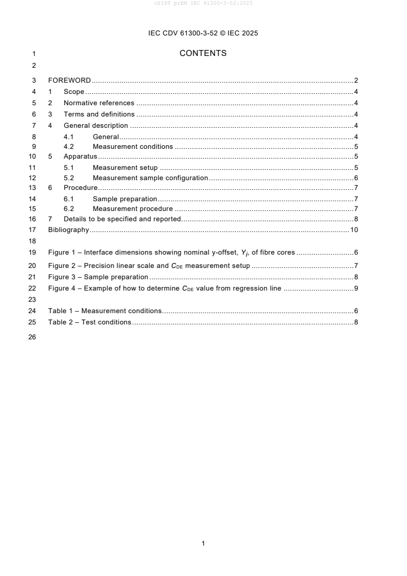
1 CONTENTS
3 FOREWORD . 2
4 1 Scope . 4
5 2 Normative references . 4
6 3 Terms and definitions . 4
7 4 General description . 4
8 4.1 General . 4
9 4.2 Measurement conditions . 5
10 5 Apparatus . 5
11 5.1 Measurement setup . 5
12 5.2 Measurement sample configuration . 6
13 6 Procedure . 7
14 6.1 Sample preparation . 7
15 6.2 Measurement procedure . 7
16 7 Details to be specified and reported. 8
17 Bibliography . 10
19 Figure 1 – Interface dimensions showing nominal y-offset, Y , of fibre cores . 6
i
20 Figure 2 – Precision linear scale and CDE measurement setup . 7
21 Figure 3 – Sample preparation . 8
22 Figure 4 – Example of how to determine CDE value from regression line . 9
24 Table 1 – Measurement conditions. 6
25 Table 2 – Test conditions . 8
oSIST prEN IEC 61300-3-52:2025
IEC CDV 61300-3-52 © IEC 2025
27 INTERNATIONAL ELECTROTECHNICAL COMMISSION
28 ____________
30 FIBRE OPTIC INTERCONNECTING
31 DEVICES AND PASSIVE COMPONENTS –
32 BASIC TEST AND MEASUREMENT PROCEDURES –
34 Part 3-52: Examinations and measurements –
35 Guide pin hole and guide pin deformation constant for angled physically
36 contacting rectangular ferrules with single-mode fibre
40 FOREWORD
41 1) The International Electrotechnical Commission (IEC) is a worldwide organization for standardization comprising
42 all national electrotechnical committees (IEC National Committees). The object of IEC is to promote international
43 co-operation on all questions concerning standardization in the electrical and electronic fields. To this end and
44 in addition to other activities, IEC publishes International Standards, Technical Specifications, Technical Reports,
45 Publicly Available Specifications (PAS) and Guides (hereafter referred to as “IEC Publication(s)”). Their
46 preparation is entrusted to technical committees; any IEC National Committee interested in the subject dealt with
47 may participate in this preparatory work. International, governmental and non-governmental organizations liaising
48 with the IEC also participate in this preparation. IEC collaborates closely with the International Organization for
49 Standardization (ISO) in accordance with conditions determined by agreement between the two organizations.
50 2) The formal decisions or agreements of IEC on technical matters express, as nearly as possible, an international
51 consensus of opinion on the relevant subjects since each technical committee has representation from all
52 interested IEC National Committees.
53 3) IEC Publications have the form of recommendations for international use and are accepted by IEC National
54 Committees in that sense. While all reasonable efforts are made to ensure that the technical content of IEC
55 Publications is accurate, IEC cannot be held responsible for the way in which they are used or for any
56 misinterpretation by any end user.
57 4) In order to promote international uniformity, IEC National Committees undertake to apply IEC Publications
58 transparently to the maximum extent possible in their national and regional publications. Any divergence between
59 any IEC Publication and the corresponding national or regional publication shall be clearly indicated in the latter.
60 5) IEC itself does not provide any attestation of conformity. Independent certification bodies provide conformity
61 assessment services and, in some areas, access to IEC marks of conformity. IEC is not responsible for any
62 services carried out by independent certification bodies.
63 6) All users should ensure that they have the latest edition of this publication.
64 7) No liability shall attach to IEC or its directors, employees, servants or agents including individual experts and
65 members of its technical committees and IEC National Committees for any personal injury, property damage or
66 other damage of any nature whatsoever, whether direct or indirect, or for costs (including legal fees) and
67 expenses arising out of the publication, use of, or reliance upon, this IEC Publication or any other IEC Publications.
68 8) Attention is drawn to the Normative references cited in this publication. Use of the referenced publications is
69 indispensable for the correct application of this publication.
70 9) Attention is drawn to the possibility that some of the elements of this IEC Publication may be the subject of patent
71 rights. IEC shall not be held responsible for identifying any or all such patent rights.
72 International Standard IEC 61300-3-52 has been prepared by subcommittee 86B: Fibre optic
73 interconnecting devices and passive components, of IEC technical committee 86: Fibre optics.
74 This second edition cancels and replaces the first edition published in 2014. This edition constitutes a
75 technical revision.
76 This edition includes the following significant technical changes with respect to the previous edition:
77 a) Inclusion of 19,6 N mating force and 0,5480 mm diameter pins, which covers 16 fibre and
78 multi-row ferrule variants.
79 b) Clarification to CDE measurement setup.
80 c) Improved definition of α parameter.
81 The text of this standard is based on the following documents:
oSIST prEN IEC 61300-3-52:2025
IEC CDV 61300-3-52 © IEC 2025
FDIS Report on voting
86B/xxxx/FDIS 86
...