

SIST EN 300 175-4 V2.2.1:2009
Digital Enhanced Cordless Telecommunications (DECT) - Common Interface (CI) - Part 4: Data Link Control (DLC) layer
General Information
- Abstract
The present document is one of the parts of the specification of the Digital Enhanced Cordless Telecommunications (DECT) Common Interface (CI). The present document specifies the Data Link Control (DLC) layer. The DLC layer is part 4 of the DECT CI standard and layer 2b of the DECT protocol stack. Two planes of operation are specified for this DLC (sub)layer. These planes are called the Control plane (C-plane) and the User plane (U-plane). The C-plane is mostly concerned with the DECT signalling aspects. It provides a reliable point-to-point service that uses a link access protocol to offer error protected transmission of Network (NWK) layer messages. The C-plane also provides a separate point-to-multipoint (broadcast) service (Lb). The U-plane is only concerned with end-to-end user information. This plane contains most of the application dependent procedures of DECT. Several alternative services (both circuit-mode and packet-mode) are defined as a family of independent entities. Each service provides one or more point-to-point U-plane data links, where the detailed characteristics of those links are determined by the particular needs of each service. The defined services cover a wide range of performance, from "unprotected with low delay" for speech applications to "highly protected with variable delay", for local area network applications. NOTE: The performance of the DLC services need not be tight to any particular application. For example the "unprotected with low delay" service could also be used for data applications, e.g. if some data protection is provided outside the DECT protocol.
The present document uses the layered model principles and terminology as described in ITU-T Recommendation X.200 [14] and ITU-T Recommendation X.210 [15]. The present document includes New Generation DECT, a further development of the DECT standard introducing wideband speech, improved data services, new slot types and other technical enhancements.
- Status
- Published
- Publication Date
- 20-Nov-2008
- Technical Committee
- MOC - Mobile Communications
- Current Stage
- 6060 - National Implementation/Publication (Adopted Project)
- Start Date
- 14-Nov-2008
- Due Date
- 19-Jan-2009
- Completion Date
- 21-Nov-2008
Buy Documents
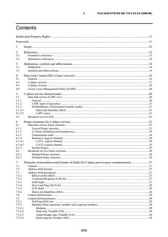
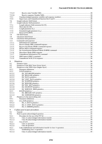
ETSI EN 300 175-4 V2.2.0 (2008-06) - Digital Enhanced Cordless Telecommunications (DECT); Common Interface (CI); Part 4: Data Link Control (DLC) layer
ETSI EN 300 175-4 V2.2.1 (2008-11) - Digital Enhanced Cordless Telecommunications (DECT); Common Interface (CI); Part 4: Data Link Control (DLC) layer


Overview
SIST EN 300 175-4 V2.2.1:2009 is a critical standard in the Digital Enhanced Cordless Telecommunications (DECT) series, addressing the Common Interface (CI) - Part 4: Data Link Control (DLC) layer. Developed by SIST and aligned with the European ETSI EN 300 175-4, this specification defines the comprehensive requirements and functionalities of the DLC layer within the DECT protocol stack. The DLC layer, also known as layer 2b, is essential for ensuring reliable and efficient communication between cordless telecommunication devices, supporting both signaling and user data transmission.
Key Topics
Data Link Control Layer Fundamentals
- Specifies the structure and operation of the DECT data link layer.
- Defines two distinct planes:
- Control Plane (C-plane): Specializes in signaling and provides reliable, point-to-point and broadcast communication, employing error protection for network messages.
- User Plane (U-plane): Manages end-to-end user data transmission and hosts application-dependent procedures for both circuit-mode and packet-mode services.
Service Flexibility
- Offers a range of data link services, from unprotected low-delay for voice (speech) applications to highly protected, variable delay for local area network (LAN) data transfer.
- Each service is tailored to meet the performance requirements of diverse telecommunication applications.
Layered Model and Interoperability
- Adopts methodologies and terminology from ITU-T Recommendations X.200 and X.210 for layered networking architecture.
- Facilitates integration and compatibility with international telecommunication systems.
Support for New Generation DECT
- Includes enhancements for advanced features such as wideband speech and improved data services, supporting modern requirements in cordless communications.
Applications
The Data Link Control layer as defined in SIST EN 300 175-4 V2.2.1:2009 is foundational in DECT-based systems and supports a wide range of professional and consumer applications, including:
Cordless Telephony
- Ensures secure and high-quality voice and data exchange in home and enterprise cordless phones.
Wireless Data Transmission
- Powers DECT-enabled local area networks by providing reliable and protected data transport for business environments.
Public and Private Mobile Radio
- Enhances mobility and connectivity in applications such as hospital communication systems, warehouses, and manufacturing plants.
Broadband and Packet Data Services
- Supports various forms of digital data communication, including wideband audio and high-rate data transfer for future-proof DECT deployments.
Integration with IMT-2000 and Mobility Services
- Facilitates global mobility and roaming features for wireless handsets and portable devices using TDD and TDMA technologies.
Related Standards
To achieve full compliance and interoperability within the DECT ecosystem, consider these associated standards:
- SIST EN 300 175-1: DECT Common Interface (CI); Overview and general description.
- SIST EN 300 175-2: Physical layer specifications of DECT CI.
- SIST EN 300 175-3: Medium Access Control (MAC) layer requirements.
- SIST EN 300 175-5: Network layer definitions.
- ITU-T X.200 and X.210: Reference for open systems interconnection layered models.
For more details and the latest updates, visit ETSI's DECT standards portal.
Keywords: DECT, Data Link Control, wireless telecommunications, cordless communications, common interface, protocol stack, signaling, user data, mobility, TDMA, TDD, standards, SIST EN 300 175-4
Buy Documents
ETSI EN 300 175-4 V2.2.0 (2008-06) - Digital Enhanced Cordless Telecommunications (DECT); Common Interface (CI); Part 4: Data Link Control (DLC) layer
ETSI EN 300 175-4 V2.2.1 (2008-11) - Digital Enhanced Cordless Telecommunications (DECT); Common Interface (CI); Part 4: Data Link Control (DLC) layer
Get Certified
Connect with accredited certification bodies for this standard

BSI Group
BSI (British Standards Institution) is the business standards company that helps organizations make excellence a habit.

NYCE
Mexican standards and certification body.

ANCE
Mexican certification and testing association.
Sponsored listings
Frequently Asked Questions
SIST EN 300 175-4 V2.2.1:2009 is a standard published by the Slovenian Institute for Standardization (SIST). Its full title is "Digital Enhanced Cordless Telecommunications (DECT) - Common Interface (CI) - Part 4: Data Link Control (DLC) layer". This standard covers: The present document is one of the parts of the specification of the Digital Enhanced Cordless Telecommunications (DECT) Common Interface (CI). The present document specifies the Data Link Control (DLC) layer. The DLC layer is part 4 of the DECT CI standard and layer 2b of the DECT protocol stack. Two planes of operation are specified for this DLC (sub)layer. These planes are called the Control plane (C-plane) and the User plane (U-plane). The C-plane is mostly concerned with the DECT signalling aspects. It provides a reliable point-to-point service that uses a link access protocol to offer error protected transmission of Network (NWK) layer messages. The C-plane also provides a separate point-to-multipoint (broadcast) service (Lb). The U-plane is only concerned with end-to-end user information. This plane contains most of the application dependent procedures of DECT. Several alternative services (both circuit-mode and packet-mode) are defined as a family of independent entities. Each service provides one or more point-to-point U-plane data links, where the detailed characteristics of those links are determined by the particular needs of each service. The defined services cover a wide range of performance, from "unprotected with low delay" for speech applications to "highly protected with variable delay", for local area network applications. NOTE: The performance of the DLC services need not be tight to any particular application. For example the "unprotected with low delay" service could also be used for data applications, e.g. if some data protection is provided outside the DECT protocol. The present document uses the layered model principles and terminology as described in ITU-T Recommendation X.200 [14] and ITU-T Recommendation X.210 [15]. The present document includes New Generation DECT, a further development of the DECT standard introducing wideband speech, improved data services, new slot types and other technical enhancements.
The present document is one of the parts of the specification of the Digital Enhanced Cordless Telecommunications (DECT) Common Interface (CI). The present document specifies the Data Link Control (DLC) layer. The DLC layer is part 4 of the DECT CI standard and layer 2b of the DECT protocol stack. Two planes of operation are specified for this DLC (sub)layer. These planes are called the Control plane (C-plane) and the User plane (U-plane). The C-plane is mostly concerned with the DECT signalling aspects. It provides a reliable point-to-point service that uses a link access protocol to offer error protected transmission of Network (NWK) layer messages. The C-plane also provides a separate point-to-multipoint (broadcast) service (Lb). The U-plane is only concerned with end-to-end user information. This plane contains most of the application dependent procedures of DECT. Several alternative services (both circuit-mode and packet-mode) are defined as a family of independent entities. Each service provides one or more point-to-point U-plane data links, where the detailed characteristics of those links are determined by the particular needs of each service. The defined services cover a wide range of performance, from "unprotected with low delay" for speech applications to "highly protected with variable delay", for local area network applications. NOTE: The performance of the DLC services need not be tight to any particular application. For example the "unprotected with low delay" service could also be used for data applications, e.g. if some data protection is provided outside the DECT protocol. The present document uses the layered model principles and terminology as described in ITU-T Recommendation X.200 [14] and ITU-T Recommendation X.210 [15]. The present document includes New Generation DECT, a further development of the DECT standard introducing wideband speech, improved data services, new slot types and other technical enhancements.
SIST EN 300 175-4 V2.2.1:2009 is classified under the following ICS (International Classification for Standards) categories: 33.070.30 - Digital Enhanced Cordless Telecommunications (DECT); 35.100.20 - Data link layer. The ICS classification helps identify the subject area and facilitates finding related standards.
SIST EN 300 175-4 V2.2.1:2009 is available in PDF format for immediate download after purchase. The document can be added to your cart and obtained through the secure checkout process. Digital delivery ensures instant access to the complete standard document.
Standards Content (Sample)
Final draft ETSI EN 300 175-4 V2.2.0 (2008-06)
European Standard (Telecommunications series)
Digital Enhanced Cordless Telecommunications (DECT);
Common Interface (CI);
Part 4: Data Link Control (DLC) layer
2 Final draft ETSI EN 300 175-4 V2.2.0 (2008-06)
Reference
REN/DECT-000248-4
Keywords
DECT, IMT-2000, mobility, radio, TDD, TDMA
ETSI
650 Route des Lucioles
F-06921 Sophia Antipolis Cedex - FRANCE
Tel.: +33 4 92 94 42 00 Fax: +33 4 93 65 47 16
Siret N° 348 623 562 00017 - NAF 742 C
Association à but non lucratif enregistrée à la
Sous-Préfecture de Grasse (06) N° 7803/88
Important notice
Individual copies of the present document can be downloaded from:
http://www.etsi.org
The present document may be made available in more than one electronic version or in print. In any case of existing or
perceived difference in contents between such versions, the reference version is the Portable Document Format (PDF).
In case of dispute, the reference shall be the printing on ETSI printers of the PDF version kept on a specific network drive
within ETSI Secretariat.
Users of the present document should be aware that the document may be subject to revision or change of status.
Information on the current status of this and other ETSI documents is available at
http://portal.etsi.org/tb/status/status.asp
If you find errors in the present document, please send your comment to one of the following services:
http://portal.etsi.org/chaircor/ETSI_support.asp
Copyright Notification
No part may be reproduced except as authorized by written permission.
The copyright and the foregoing restriction extend to reproduction in all media.
© European Telecommunications Standards Institute 2008.
All rights reserved.
TM TM TM TM
DECT , PLUGTESTS , UMTS , TIPHON , the TIPHON logo and the ETSI logo are Trade Marks of ETSI registered
for the benefit of its Members.
TM
3GPP is a Trade Mark of ETSI registered for the benefit of its Members and of the 3GPP Organizational Partners.
ETSI
3 Final draft ETSI EN 300 175-4 V2.2.0 (2008-06)
Contents
Intellectual Property Rights.11
Foreword.11
1 Scope.12
2 References.12
2.1 Normative references.13
2.2 Informative references.14
3 Definitions, symbols and abbreviations .14
3.1 Definitions.14
3.2 Symbols and abbreviations.14
4 Data Link Control (DLC) layer overview .16
4.1 General.16
4.2 C-plane services.17
4.3 U-plane services.18
4.4 Lower Layer Management Entity (LLME) .20
5 C-plane service characteristics .20
5.1 Data link service (LAPC+Lc).20
5.1.1 General.20
5.1.2 LAPC types of operation .21
5.1.3 Establishment of information transfer modes .21
5.1.3.1 Data Link Identifier (DLI) .21
5.1.3.2 LAPC states.21
5.2 Broadcast service (Lb).22
6 Frame structures for C-plane services.23
6.1 Data link service frame structure.23
6.1.1 General frame structure .23
6.1.2 Lc frame delimiting and transparency .24
6.1.3 Transmission order.24
6.1.4 Routing to logical channels.24
6.1.4.1 C /CL logical channel.24
F F
6.1.4.2 C /CL logical channel.25
S S
6.1.5 Invalid frames.25
6.2 Broadcast service frame structure.26
6.2.1 Standard frame structure.26
6.2.2 Extended frame structure .26
7 Elements of procedures and formats of fields for C-plane peer-to-peer communication.27
7.1 General.27
7.2 Address field formats.27
7.3 Address field parameters.27
7.3.1 REServed bit (RES).27
7.3.2 Command Response (C/R) bit .27
7.3.3 SAPI field.27
7.3.4 New Link Flag (NLF) bit.28
7.3.5 LLN-field.28
7.3.6 Data Link Identifiers (DLI).28
7.4 Control field formats .29
7.5 Control field parameters.29
7.5.1 Poll/Final (P/F) bit .29
7.5.2 Multiple frame operation variables and sequence numbers .29
7.5.2.1 Modulus.29
7.5.2.2 Send state Variable V(S).29
7.5.2.3 Acknowledge state Variable V(A) .30
7.5.2.4 Send sequence Number N(S) .30
ETSI
4 Final draft ETSI EN 300 175-4 V2.2.0 (2008-06)
7.5.2.5 Receive state Variable V(R).30
7.5.2.6 Receive sequence Number N(R) .30
7.5.3 Unacknowledged operation variables and sequence numbers .30
7.5.4 Supervisory and Unnumbered function bits S and U.30
7.6 Length indicator field format.30
7.7 Length indicator field parameters.31
7.7.1 Length indicator field extension bit (N).31
7.7.2 More data bit (M).31
7.7.3 Length parameter (L ) .31
I
7.7.4 Extended length parameter (L ) .32
JJ
7.7.5 Reserved bit (RES) .32
7.8 Fill field format .32
7.9 Checksum field format .32
7.10 Checksum field parameters .32
7.11 Commands and responses .34
7.11.1 Information (I) command.34
7.11.2 Receive Ready (RR) command/response.34
7.11.3 Receive Not Ready (RNR) command/response.35
7.11.4 REJect (REJ) command/response .35
7.11.5 Set Asynchronous Balanced Mode (SABM) command.35
7.11.6 Disconnect Mode (DM) response .35
7.11.7 Unnumbered Information (UI) command .35
7.11.8 DISConnect (DISC) command .36
7.11.9 Unnumbered ACK (UA) response.36
8 Primitives .36
8.1 Primitive types.36
8.2 Primitives to the MAC layer (lower layer).36
8.3 Primitives to the NWK layer (higher layer) .36
8.3.1 Parameter definitions.37
8.3.2 S-SAP primitives.38
8.3.2.1 DL_ESTABLISH primitive.38
8.3.2.2 DL_RELEASE primitive.38
8.3.2.3 DL_DATA primitive.39
8.3.2.4 DL_UNIT_DATA primitive.39
8.3.2.5 DL_SUSPEND primitive.39
8.3.2.6 DL_RESUME primitive.39
8.3.2.7 DL_ENC_KEY primitive.40
8.3.2.8 DL_ENCRYPT primitive.40
8.3.2.9 DL_SERVICE_MOD primitive.40
8.3.3 B-SAP primitives.40
8.3.3.1 DL_BROADCAST primitive.41
8.3.3.2 DL_EXPEDITED primitive.41
8.4 Primitives to the interworking unit.41
8.4.1 Parameter definitions.41
8.4.2 LU -SAP primitives .42
X
8.4.2.1 DL_U_DATA primitive.42
8.4.2.2 DL_U_UNIT_DATA primitive.42
8.4.2.3 DL_U_ERROR primitive.42
9 C-plane peer-to-peer procedures .43
9.1 General.43
9.2 Point to point acknowledged operation .43
9.2.1 Procedure for the use of the P/F bit .43
9.2.1.1 Class A acknowledged information transfer .43
9.2.1.2 Class B acknowledged information transfer .44
9.2.2 Use of LLN.44
9.2.2.1 Class A operation.44
9.2.2.2 Class B operation .44
9.2.3 Link establishment and information transfer in class A operation.44
9.2.3.1 Establishing class A operation .44
9.2.3.2 Class A acknowledged information transfer .45
ETSI
5 Final draft ETSI EN 300 175-4 V2.2.0 (2008-06)
9.2.3.3 Transmission of class A I-frames.45
9.2.3.4 Reception of class A I-frames .46
9.2.3.5 Receiving acknowledgements.46
9.2.3.6 Waiting for acknowledgement.46
9.2.3.7 Release of class A operation .47
9.2.3.8 Re-establishment of class A operation .47
9.2.4 Establishing class B multiple frame operation.47
9.2.4.1 Overview.47
9.2.4.2 Class B multiple frame establishment procedures.48
9.2.4.3 Class B LLN assignment procedures .49
9.2.4.3.1 PT establishment.49
9.2.4.3.2 FT establishment.50
9.2.5 Link maintenance and information transfer in class B multiple frame operation .50
9.2.5.1 Transmitting I-frames.50
9.2.5.2 Receiving I-frames.51
9.2.5.2.1 P bit set to 1.51
9.2.5.2.2 P bit set to 0.51
9.2.5.3 Sending and receiving acknowledgements.51
9.2.5.3.1 Sending acknowledgements.51
9.2.5.3.2 Receiving acknowledgements.51
9.2.5.4 Receiving REJ-frames.52
9.2.5.5 Receiving RNR-frames.53
9.2.5.6 LAPC own receiver busy condition .54
9.2.5.7 Waiting acknowledgement.54
9.2.5.8 Appropriate supervisory frame.55
9.2.6 Release of class B multiple frame operation.55
9.2.7 Link suspension and resumption.56
9.2.7.1 Link suspension.56
9.2.7.1.1 Class B acknowledged suspend.56
9.2.7.1.2 Unacknowledged suspend.57
9.2.7.2 Class B link resumption .58
9.2.7.3 Connection handover.59
9.2.7.3.1 Class A connection handover .60
9.2.7.3.2 Class B connection handover .61
9.2.7.3.3 Expiry of connection handover timer .61
9.2.8 Re-establishment of class B multi-frame operation .61
9.2.8.1 Criteria for re-establishment.61
9.2.8.2 Procedure.62
9.2.9 Exception handling.62
9.2.9.1 General.62
9.2.9.2 Class B exception condition reporting and recovery.63
9.2.9.2.1 N(S) sequence error.63
9.2.9.2.2 N(R) sequence error .63
9.2.9.2.3 Timer recovery condition .63
9.2.9.2.4 Collision of identical transmitted and received commands .63
9.3 Unacknowledged operation.64
9.3.1 Use of LLN for unacknowledged information transfer.64
9.3.2 Class U link establishment.64
9.3.3 Unacknowledged information transfer.64
9.3.3.1 Transmission of unacknowledged information .64
9.3.3.2 Reception of unacknowledged information .64
9.3.4 Unacknowledged release.64
9.4 Broadcast operation.65
9.4.1 Normal operation.65
9.4.1.1 Procedure in the Fixed radio Termination (FT) .65
9.4.1.2 Procedure in the Portable radio Termination (PT) .65
9.4.2 Expedited operation.65
9.4.2.1 Procedure in the Fixed radio Termination (FT) .65
9.4.2.2 Procedure in the Portable radio Termination (PT) .65
9.5 MAC layer interfaces .66
9.5.1 MC-SAP.66
9.5.1.1 C-plane overview.66
ETSI
6 Final draft ETSI EN 300 175-4 V2.2.0 (2008-06)
9.5.1.2 C-plane service data procedures.66
9.5.1.3 U-plane service data.67
9.5.2 MB-SAP.67
9.5.2.1 C-plane service data procedures.67
9.5.2.2 U-plane service data.67
9.5.3 MA-SAP.68
9.5.3.1 Overview.68
9.5.3.2 Service data procedures.68
10 Management procedures.68
10.1 Lower Layer Management Entity (LLME) .68
10.2 MAC connection management.69
10.2.1 MAC connection set-up.69
10.2.2 MAC connection release.69
10.2.3 MAC connection modification.69
10.2.4 MAC connection identifiers.70
10.2.4.1 Overview.70
10.2.4.2 Advanced MAC Connection Identifiers (AMCI).70
10.2.4.3 Basic MAC Connection Identifiers (BMCI) .71
10.2.4.4 MAC Connection Endpoint Identifier (MCEI) .71
10.2.5 Selection of logical channel (C or C ).71
S F
10.3 DLC C-plane (LAPC) management .72
10.3.1 Provision of link signature.72
10.3.2 Routing of connection oriented links.72
10.3.3 Routing of connectionless links.73
10.4 DLC U-plane (LUX) management.73
10.4.1 U-plane establishment.73
10.4.2 U-plane release.73
10.4.3 U-plane suspend and resume .73
10.5 Connection handover management .74
10.6 Ciphering management.74
10.6.1 Ciphering management in cases where the NWK layer executes the ciphering related MM procedure .74
10.6.1.1 Providing a key to the MAC layer .74
10.6.1.2 Starting and stopping the ciphering.75
10.6.1.3 Connection handover.75
10.6.2 Ciphering management in cases where the NWK layer does not execute the ciphering related MM
procedure .75
10.7 Broadband data link management .75
11 U-plane service characteristics.76
11.1 General.76
11.2 LU1 TRansparent UnProtected service (TRUP) .76
11.3 LU2 Frame RELay service (FREL).77
11.3.1 General.77
11.3.2 Checksum operation.78
11.3.3 Segmentation and transmission class.78
11.3.4 Data transmission.79
11.3.4.1 Send side procedure .79
11.3.4.2 Receive side procedure.79
11.4 LU3 Frame SWItching service (FSWI).80
11.5 LU4 Forward Error Correction (FEC) service.80
11.6 LU5 Basic Rate Adaption service (BRAT) .81
11.6.1 Overview.81
11.6.2 Protected service operation.82
11.6.2.1 General.82
11.6.2.2 Data buffering and initial rate adaptation.82
11.6.2.3 Multi-channel set multiplexing.83
11.6.2.4 Segmentation of Multiplexed Data Units (MDU).84
11.6.2.5 Frame sequencing and addition of control and fill octets.85
11.6.2.6 Frame transmission.86
11.6.3 Unprotected service operation .87
11.6.3.1 General.87
ETSI
7 Final draft ETSI EN 300 175-4 V2.2.0 (2008-06)
11.6.3.2 Data buffering and initial rate adaption.87
11.6.3.3 Multi-channel set multiplexing.87
11.6.3.4 Segmentation of MDUs.89
11.6.3.5 Frame transmission.89
11.7 LU6 Secondary Rate AdapTion (SRAT) service .89
11.7.1 General.89
11.8 LU16 ESCape Service (ESC).90
11.8.1 General.90
11.9 LU7 64 kbit/s data bearer service.91
11.9.1 General.91
11.9.2 Physical layer service.91
11.9.3 MAC layer service.91
11.9.4 DLC layer service .91
11.9.4.1 Architectural model.91
11.9.4.1.1 Transmit (Tx) frame buffering .92
11.9.4.1.2 Receive (Rx) frame buffering.92
11.9.4.2 Automatic-Repeat-Request (ARQ) and Forward Error Control (FEC).92
11.9.4.2.1 Control field .93
11.9.4.2.2 Information field.95
11.9.4.2.3 ARQ checksum.96
11.9.4.3 Procedures for normal operation.96
11.9.4.3.1 Establishment and synchronization procedures.96
11.9.4.3.2 Active phase .98
11.9.4.3.3 Release.100
11.9.4.4 Exceptional procedures.100
11.9.4.4.1 Invalid frame condition.100
11.9.4.4.2 Establishment.100
11.9.4.4.3 Transmitting frames.100
11.9.4.4.4 Receiving frames.100
11.9.4.4.5 Sending acknowledgements.101
11.9.4.4.6 Forwarding of received data.101
11.9.4.4.7 N(R) sequence error .101
11.9.4.4.8 N(O) sequence error .101
11.9.4.4.9 N(S) sequence error.102
11.9.4.4.10 Format error.102
11.9.4.4.11 Abnormal release.102
11.9.4.4.12 Implicit reset.102
11.9.5 Network layer service .102
11.9.5.1 LCE service.102
11.9.5.2 CC service.102
11.10 LU8 service.
...
European Standard (Telecommunications series)
Digital Enhanced Cordless Telecommunications (DECT);
Common Interface (CI);
Part 4: Data Link Control (DLC) layer
2 ETSI EN 300 175-4 V2.2.1 (2008-11)
Reference
REN/DECT-000248-4
Keywords
DECT, IMT-2000, mobility, radio, TDD, TDMA
ETSI
650 Route des Lucioles
F-06921 Sophia Antipolis Cedex - FRANCE
Tel.: +33 4 92 94 42 00 Fax: +33 4 93 65 47 16
Siret N° 348 623 562 00017 - NAF 742 C
Association à but non lucratif enregistrée à la
Sous-Préfecture de Grasse (06) N° 7803/88
Important notice
Individual copies of the present document can be downloaded from:
http://www.etsi.org
The present document may be made available in more than one electronic version or in print. In any case of existing or
perceived difference in contents between such versions, the reference version is the Portable Document Format (PDF).
In case of dispute, the reference shall be the printing on ETSI printers of the PDF version kept on a specific network drive
within ETSI Secretariat.
Users of the present document should be aware that the document may be subject to revision or change of status.
Information on the current status of this and other ETSI documents is available at
http://portal.etsi.org/tb/status/status.asp
If you find errors in the present document, please send your comment to one of the following services:
http://portal.etsi.org/chaircor/ETSI_support.asp
Copyright Notification
No part may be reproduced except as authorized by written permission.
The copyright and the foregoing restriction extend to reproduction in all media.
© European Telecommunications Standards Institute 2008.
All rights reserved.
TM TM TM TM
DECT , PLUGTESTS , UMTS , TIPHON , the TIPHON logo and the ETSI logo are Trade Marks of ETSI registered
for the benefit of its Members.
TM
3GPP is a Trade Mark of ETSI registered for the benefit of its Members and of the 3GPP Organizational Partners.
ETSI
3 ETSI EN 300 175-4 V2.2.1 (2008-11)
Contents
Intellectual Property Rights.11
Foreword.11
1 Scope.12
2 References.12
2.1 Normative references.13
2.2 Informative references.14
3 Definitions, symbols and abbreviations .14
3.1 Definitions.14
3.2 Symbols and abbreviations.14
4 Data Link Control (DLC) layer overview .16
4.1 General.16
4.2 C-plane services.17
4.3 U-plane services.18
4.4 Lower Layer Management Entity (LLME) .20
5 C-plane service characteristics .20
5.1 Data link service (LAPC+Lc).20
5.1.1 General.20
5.1.2 LAPC types of operation .21
5.1.3 Establishment of information transfer modes .21
5.1.3.1 Data Link Identifier (DLI) .21
5.1.3.2 LAPC states.21
5.2 Broadcast service (Lb).22
6 Frame structures for C-plane services.23
6.1 Data link service frame structure.23
6.1.1 General frame structure .23
6.1.2 Lc frame delimiting and transparency .24
6.1.3 Transmission order.24
6.1.4 Routing to logical channels.24
6.1.4.1 C /CL logical channel.24
F F
6.1.4.2 C /CL logical channel.25
S S
6.1.5 Invalid frames.25
6.2 Broadcast service frame structure.26
6.2.1 Standard frame structure.26
6.2.2 Extended frame structure .26
7 Elements of procedures and formats of fields for C-plane peer-to-peer communication.27
7.1 General.27
7.2 Address field formats.27
7.3 Address field parameters.27
7.3.1 REServed bit (RES).27
7.3.2 Command Response (C/R) bit .27
7.3.3 SAPI field.27
7.3.4 New Link Flag (NLF) bit.28
7.3.5 LLN-field.28
7.3.6 Data Link Identifiers (DLI).28
7.4 Control field formats .29
7.5 Control field parameters.29
7.5.1 Poll/Final (P/F) bit .29
7.5.2 Multiple frame operation variables and sequence numbers .29
7.5.2.1 Modulus.29
7.5.2.2 Send state Variable V(S).29
7.5.2.3 Acknowledge state Variable V(A) .30
7.5.2.4 Send sequence Number N(S) .30
ETSI
4 ETSI EN 300 175-4 V2.2.1 (2008-11)
7.5.2.5 Receive state Variable V(R).30
7.5.2.6 Receive sequence Number N(R) .30
7.5.3 Unacknowledged operation variables and sequence numbers .30
7.5.4 Supervisory and Unnumbered function bits S and U.30
7.6 Length indicator field format.30
7.7 Length indicator field parameters.31
7.7.1 Length indicator field extension bit (N).31
7.7.2 More data bit (M).31
7.7.3 Length parameter (L ) .31
I
7.7.4 Extended length parameter (L ) .32
JJ
7.7.5 Reserved bit (RES) .32
7.8 Fill field format .32
7.9 Checksum field format .32
7.10 Checksum field parameters .32
7.11 Commands and responses .34
7.11.1 Information (I) command.34
7.11.2 Receive Ready (RR) command/response.34
7.11.3 Receive Not Ready (RNR) command/response.35
7.11.4 REJect (REJ) command/response .35
7.11.5 Set Asynchronous Balanced Mode (SABM) command.35
7.11.6 Disconnect Mode (DM) response .35
7.11.7 Unnumbered Information (UI) command .35
7.11.8 DISConnect (DISC) command .36
7.11.9 Unnumbered ACK (UA) response.36
8 Primitives .36
8.1 Primitive types.36
8.2 Primitives to the MAC layer (lower layer).36
8.3 Primitives to the NWK layer (higher layer) .36
8.3.1 Parameter definitions.37
8.3.2 S-SAP primitives.38
8.3.2.1 DL_ESTABLISH primitive.38
8.3.2.2 DL_RELEASE primitive.38
8.3.2.3 DL_DATA primitive.39
8.3.2.4 DL_UNIT_DATA primitive.39
8.3.2.5 DL_SUSPEND primitive.39
8.3.2.6 DL_RESUME primitive.39
8.3.2.7 DL_ENC_KEY primitive.40
8.3.2.8 DL_ENCRYPT primitive.40
8.3.2.9 DL_SERVICE_MOD primitive.40
8.3.3 B-SAP primitives.40
8.3.3.1 DL_BROADCAST primitive.41
8.3.3.2 DL_EXPEDITED primitive.41
8.4 Primitives to the interworking unit.41
8.4.1 Parameter definitions.41
8.4.2 LU -SAP primitives .42
X
8.4.2.1 DL_U_DATA primitive.42
8.4.2.2 DL_U_UNIT_DATA primitive.42
8.4.2.3 DL_U_ERROR primitive.42
9 C-plane peer-to-peer procedures .43
9.1 General.43
9.2 Point to point acknowledged operation .43
9.2.1 Procedure for the use of the P/F bit .43
9.2.1.1 Class A acknowledged information transfer .43
9.2.1.2 Class B acknowledged information transfer .44
9.2.2 Use of LLN.44
9.2.2.1 Class A operation.44
9.2.2.2 Class B operation .44
9.2.3 Link establishment and information transfer in class A operation.44
9.2.3.1 Establishing class A operation .44
9.2.3.2 Class A acknowledged information transfer .45
ETSI
5 ETSI EN 300 175-4 V2.2.1 (2008-11)
9.2.3.3 Transmission of class A I-frames.45
9.2.3.4 Reception of class A I-frames .46
9.2.3.5 Receiving acknowledgements.46
9.2.3.6 Waiting for acknowledgement.46
9.2.3.7 Release of class A operation .47
9.2.3.8 Re-establishment of class A operation .47
9.2.4 Establishing class B multiple frame operation.47
9.2.4.1 Overview.47
9.2.4.2 Class B multiple frame establishment procedures.48
9.2.4.3 Class B LLN assignment procedures .49
9.2.4.3.1 PT establishment.49
9.2.4.3.2 FT establishment.50
9.2.5 Link maintenance and information transfer in class B multiple frame operation .50
9.2.5.1 Transmitting I-frames.50
9.2.5.2 Receiving I-frames.51
9.2.5.2.1 P bit set to 1.51
9.2.5.2.2 P bit set to 0.51
9.2.5.3 Sending and receiving acknowledgements.51
9.2.5.3.1 Sending acknowledgements.51
9.2.5.3.2 Receiving acknowledgements.51
9.2.5.4 Receiving REJ-frames.52
9.2.5.5 Receiving RNR-frames.53
9.2.5.6 LAPC own receiver busy condition .54
9.2.5.7 Waiting acknowledgement.54
9.2.5.8 Appropriate supervisory frame.55
9.2.6 Release of class B multiple frame operation.55
9.2.7 Link suspension and resumption.56
9.2.7.1 Link suspension.56
9.2.7.1.1 Class B acknowledged suspend.56
9.2.7.1.2 Unacknowledged suspend.57
9.2.7.2 Class B link resumption .58
9.2.7.3 Connection handover.59
9.2.7.3.1 Class A connection handover .60
9.2.7.3.2 Class B connection handover .61
9.2.7.3.3 Expiry of connection handover timer .61
9.2.8 Re-establishment of class B multi-frame operation .61
9.2.8.1 Criteria for re-establishment.61
9.2.8.2 Procedure.62
9.2.9 Exception handling.62
9.2.9.1 General.62
9.2.9.2 Class B exception condition reporting and recovery.63
9.2.9.2.1 N(S) sequence error.63
9.2.9.2.2 N(R) sequence error .63
9.2.9.2.3 Timer recovery condition .63
9.2.9.2.4 Collision of identical transmitted and received commands .63
9.3 Unacknowledged operation.64
9.3.1 Use of LLN for unacknowledged information transfer.64
9.3.2 Class U link establishment.64
9.3.3 Unacknowledged information transfer.64
9.3.3.1 Transmission of unacknowledged information .64
9.3.3.2 Reception of unacknowledged information .64
9.3.4 Unacknowledged release.64
9.4 Broadcast operation.65
9.4.1 Normal operation.65
9.4.1.1 Procedure in the Fixed radio Termination (FT) .65
9.4.1.2 Procedure in the Portable radio Termination (PT) .65
9.4.2 Expedited operation.65
9.4.2.1 Procedure in the Fixed radio Termination (FT) .65
9.4.2.2 Procedure in the Portable radio Termination (PT) .65
9.5 MAC layer interfaces .66
9.5.1 MC-SAP.66
9.5.1.1 C-plane overview.66
ETSI
6 ETSI EN 300 175-4 V2.2.1 (2008-11)
9.5.1.2 C-plane service data procedures.66
9.5.1.3 U-plane service data.67
9.5.2 MB-SAP.67
9.5.2.1 C-plane service data procedures.67
9.5.2.2 U-plane service data.67
9.5.3 MA-SAP.68
9.5.3.1 Overview.68
9.5.3.2 Service data procedures.68
10 Management procedures.68
10.1 Lower Layer Management Entity (LLME) .68
10.2 MAC connection management.69
10.2.1 MAC connection set-up.69
10.2.2 MAC connection release.69
10.2.3 MAC connection modification.69
10.2.4 MAC connection identifiers.70
10.2.4.1 Overview.70
10.2.4.2 Advanced MAC Connection Identifiers (AMCI).70
10.2.4.3 Basic MAC Connection Identifiers (BMCI) .71
10.2.4.4 MAC Connection Endpoint Identifier (MCEI) .71
10.2.5 Selection of logical channel (C or C ).71
S F
10.3 DLC C-plane (LAPC) management .72
10.3.1 Provision of link signature.72
10.3.2 Routing of connection oriented links.72
10.3.3 Routing of connectionless links.73
10.4 DLC U-plane (LUX) management.73
10.4.1 U-plane establishment.73
10.4.2 U-plane release.73
10.4.3 U-plane suspend and resume .73
10.5 Connection handover management .74
10.6 Ciphering management.74
10.6.1 Ciphering management in cases where the NWK layer executes the ciphering related MM procedure .74
10.6.1.1 Providing a key to the MAC layer .74
10.6.1.2 Starting and stopping the ciphering.75
10.6.1.3 Connection handover.75
10.6.2 Ciphering management in cases where the NWK layer does not execute the ciphering related MM
procedure .75
10.7 Broadband data link management .75
11 U-plane service characteristics.76
11.1 General.76
11.2 LU1 TRansparent UnProtected service (TRUP) .76
11.3 LU2 Frame RELay service (FREL).77
11.3.1 General.77
11.3.2 Checksum operation.78
11.3.3 Segmentation and transmission class.78
11.3.4 Data transmission.79
11.3.4.1 Send side procedure .79
11.3.4.2 Receive side procedure.79
11.4 LU3 Frame SWItching service (FSWI).80
11.5 LU4 Forward Error Correction (FEC) service.80
11.6 LU5 Basic Rate Adaption service (BRAT) .81
11.6.1 Overview.81
11.6.2 Protected service operation.82
11.6.2.1 General.82
11.6.2.2 Data buffering and initial rate adaptation.82
11.6.2.3 Multi-channel set multiplexing.83
11.6.2.4 Segmentation of Multiplexed Data Units (MDU).84
11.6.2.5 Frame sequencing and addition of control and fill octets.85
11.6.2.6 Frame transmission.86
11.6.3 Unprotected service operation .87
11.6.3.1 General.87
ETSI
7 ETSI EN 300 175-4 V2.2.1 (2008-11)
11.6.3.2 Data buffering and initial rate adaption.87
11.6.3.3 Multi-channel set multiplexing.87
11.6.3.4 Segmentation of MDUs.89
11.6.3.5 Frame transmission.89
11.7 LU6 Secondary Rate AdapTion (SRAT) service .89
11.7.1 General.89
11.8 LU16 ESCape Service (ESC).90
11.8.1 General.90
11.9 LU7 64 kbit/s data bearer service.91
11.9.1 General.91
11.9.2 Physical layer service.91
11.9.3 MAC layer service.91
11.9.4 DLC layer service .91
11.9.4.1 Architectural model.91
11.9.4.1.1 Transmit (Tx) frame buffering .92
11.9.4.1.2 Receive (Rx) frame buffering.92
11.9.4.2 Automatic-Repeat-Request (ARQ) and Forward Error Control (FEC).92
11.9.4.2.1 Control field .93
11.9.4.2.2 Information field.95
11.9.4.2.3 ARQ checksum.96
11.9.4.3 Procedures for normal operation.96
11.9.4.3.1 Establishment and synchronization procedures.96
11.9.4.3.2 Active phase .98
11.9.4.3.3 Release.100
11.9.4.4 Exceptional procedures.100
11.9.4.4.1 Invalid frame condition.100
11.9.4.4.2 Establishment.100
11.9.4.4.3 Transmitting frames.100
11.9.4.4.4 Receiving frames.100
11.9.4.4.5 Sending acknowledgements.101
11.9.4.4.6 Forwarding of received data.101
11.9.4.4.7 N(R) sequence error .101
11.9.4.4.8 N(O) sequence error .101
11.9.4.4.9 N(S) sequence error.102
11.9.4.4.10 Format error.102
11.9.4.4.11 Abnormal release.102
11.9.4.4.12 Implicit reset.102
11.9.5 Network layer service .102
11.9.5.1 LCE service.102
11.9.5.2 CC service.102
11.10 LU8 service.103
11.10.1 Physical layer service.
...
2003-01.Slovenski inštitut za standardizacijo. Razmnoževanje celote ali delov tega standarda ni dovoljeno.Digital Enhanced Cordless Telecommunications (DECT) - Common Interface (CI) - Part 4: Data Link Control (DLC) layer35.100.20Podatkovni povezovalni slojData link layer33.070.30'(&7Digital Enhanced Cordless Telecommunications (DECT)ICS:Ta slovenski standard je istoveten z:EN 300 175-4 Version 2.2.1SIST EN 300 175-4 V2.2.1:2009en01-januar-2009SIST EN 300 175-4 V2.2.1:2009SLOVENSKI
STANDARD
ETSI ETSI EN 300 175-4 V2.2.1 (2008-11) 2
Reference REN/DECT-000248-4 Keywords DECT, IMT-2000, mobility, radio, TDD, TDMA ETSI 650 Route des Lucioles F-06921 Sophia Antipolis Cedex - FRANCE
Tel.: +33 4 92 94 42 00
Fax: +33 4 93 65 47 16
Siret N° 348 623 562 00017 - NAF 742 C Association à but non lucratif enregistrée à la Sous-Préfecture de Grasse (06) N° 7803/88
Important notice Individual copies of the present document can be downloaded from: http://www.etsi.org The present document may be made available in more than one electronic version or in print. In any case of existing or perceived difference in contents between such versions, the reference version is the Portable Document Format (PDF). In case of dispute, the reference shall be the printing on ETSI printers of the PDF version kept on a specific network drive within ETSI Secretariat. Users of the present document should be aware that the document may be subject to revision or change of status. Information on the current status of this and other ETSI documents is available at http://portal.etsi.org/tb/status/status.asp If you find errors in the present document, please send your comment to one of the following services: http://portal.etsi.org/chaircor/ETSI_support.asp Copyright Notification No part may be reproduced except as authorized by written permission. The copyright and the foregoing restriction extend to reproduction in all media.
© European Telecommunications Standards Institute 2008. All rights reserved.
DECTTM, PLUGTESTSTM, UMTSTM, TIPHONTM, the TIPHON logo and the ETSI logo are Trade Marks of ETSI registered for the benefit of its Members. 3GPPTM is a Trade Mark of ETSI registered for the benefit of its Members and of the 3GPP Organizational Partners. SIST EN 300 175-4 V2.2.1:2009
ETSI ETSI EN 300 175-4 V2.2.1 (2008-11) 3
Contents Intellectual Property Rights.11 Foreword.11 1 Scope.12 2 References.12 2.1 Normative references.13 2.2 Informative references.14 3 Definitions, symbols and abbreviations.14 3.1 Definitions.14 3.2 Symbols and abbreviations.14 4 Data Link Control (DLC) layer overview.16 4.1 General.16 4.2 C-plane services.17 4.3 U-plane services.18 4.4 Lower Layer Management Entity (LLME).20 5 C-plane service characteristics.20 5.1 Data link service (LAPC+Lc).20 5.1.1 General.20 5.1.2 LAPC types of operation.21 5.1.3 Establishment of information transfer modes.21 5.1.3.1 Data Link Identifier (DLI).21 5.1.3.2 LAPC states.21 5.2 Broadcast service (Lb).22 6 Frame structures for C-plane services.23 6.1 Data link service frame structure.23 6.1.1 General frame structure.23 6.1.2 Lc frame delimiting and transparency.24 6.1.3 Transmission order.24 6.1.4 Routing to logical channels.24 6.1.4.1 CF/CLF logical channel.24 6.1.4.2 CS/CLS logical channel.25 6.1.5 Invalid frames.25 6.2 Broadcast service frame structure.26 6.2.1 Standard frame structure.26 6.2.2 Extended frame structure.26 7 Elements of procedures and formats of fields for C-plane peer-to-peer communication.27 7.1 General.27 7.2 Address field formats.27 7.3 Address field parameters.27 7.3.1 REServed bit (RES).27 7.3.2 Command Response (C/R) bit.27 7.3.3 SAPI field.27 7.3.4 New Link Flag (NLF) bit.28 7.3.5 LLN-field.28 7.3.6 Data Link Identifiers (DLI).28 7.4 Control field formats.29 7.5 Control field parameters.29 7.5.1 Poll/Final (P/F) bit.29 7.5.2 Multiple frame operation variables and sequence numbers.29 7.5.2.1 Modulus.29 7.5.2.2 Send state Variable V(S).29 7.5.2.3 Acknowledge state Variable V(A).30 7.5.2.4 Send sequence Number N(S).30 SIST EN 300 175-4 V2.2.1:2009
ETSI ETSI EN 300 175-4 V2.2.1 (2008-11) 4
7.5.2.5 Receive state Variable V(R).30 7.5.2.6 Receive sequence Number N(R).30 7.5.3 Unacknowledged operation variables and sequence numbers.30 7.5.4 Supervisory and Unnumbered function bits S and U.30 7.6 Length indicator field format.30 7.7 Length indicator field parameters.31 7.7.1 Length indicator field extension bit (N).31 7.7.2 More data bit (M).31 7.7.3 Length parameter (LI).31 7.7.4 Extended length parameter (LJJ).32 7.7.5 Reserved bit (RES).32 7.8 Fill field format.32 7.9 Checksum field format.32 7.10 Checksum field parameters.32 7.11 Commands and responses.34 7.11.1 Information (I) command.34 7.11.2 Receive Ready (RR) command/response.34 7.11.3 Receive Not Ready (RNR) command/response.35 7.11.4 REJect (REJ) command/response.35 7.11.5 Set Asynchronous Balanced Mode (SABM) command.35 7.11.6 Disconnect Mode (DM) response.35 7.11.7 Unnumbered Information (UI) command.35 7.11.8 DISConnect (DISC) command.36 7.11.9 Unnumbered ACK (UA) response.36 8 Primitives.36 8.1 Primitive types.36 8.2 Primitives to the MAC layer (lower layer).36 8.3 Primitives to the NWK layer (higher layer).36 8.3.1 Parameter definitions.37 8.3.2 S-SAP primitives.38 8.3.2.1 DL_ESTABLISH primitive.38 8.3.2.2 DL_RELEASE primitive.38 8.3.2.3 DL_DATA primitive.39 8.3.2.4 DL_UNIT_DATA primitive.39 8.3.2.5 DL_SUSPEND primitive.39 8.3.2.6 DL_RESUME primitive.39 8.3.2.7 DL_ENC_KEY primitive.40 8.3.2.8 DL_ENCRYPT primitive.40 8.3.2.9 DL_SERVICE_MOD primitive.40 8.3.3 B-SAP primitives.40 8.3.3.1 DL_BROADCAST primitive.41 8.3.3.2 DL_EXPEDITED primitive.41 8.4 Primitives to the interworking unit.41 8.4.1 Parameter definitions.41 8.4.2 LUX-SAP primitives.42 8.4.2.1 DL_U_DATA primitive.42 8.4.2.2 DL_U_UNIT_DATA primitive.42 8.4.2.3 DL_U_ERROR primitive.42 9 C-plane peer-to-peer procedures.43 9.1 General.43 9.2 Point to point acknowledged operation.43 9.2.1 Procedure for the use of the P/F bit.43 9.2.1.1 Class A acknowledged information transfer.43 9.2.1.2 Class B acknowledged information transfer.44 9.2.2 Use of LLN.44 9.2.2.1 Class A operation.44 9.2.2.2 Class B operation.44 9.2.3 Link establishment and information transfer in class A operation.44 9.2.3.1 Establishing class A operation.44 9.2.3.2 Class A acknowledged information transfer.45 SIST EN 300 175-4 V2.2.1:2009
ETSI ETSI EN 300 175-4 V2.2.1 (2008-11) 5
9.2.3.3 Transmission of class A I-frames.45 9.2.3.4 Reception of class A I-frames.46 9.2.3.5 Receiving acknowledgements.46 9.2.3.6 Waiting for acknowledgement.46 9.2.3.7 Release of class A operation.47 9.2.3.8 Re-establishment of class A operation.47 9.2.4 Establishing class B multiple frame operation.47 9.2.4.1 Overview.47 9.2.4.2 Class B multiple frame establishment procedures.48 9.2.4.3 Class B LLN assignment procedures.49 9.2.4.3.1 PT establishment.49 9.2.4.3.2 FT establishment.50 9.2.5 Link maintenance and information transfer in class B multiple frame operation.50 9.2.5.1 Transmitting I-frames.50 9.2.5.2 Receiving I-frames.51 9.2.5.2.1 P bit set to 1.51 9.2.5.2.2 P bit set to 0.51 9.2.5.3 Sending and receiving acknowledgements.51 9.2.5.3.1 Sending acknowledgements.51 9.2.5.3.2 Receiving acknowledgements.51 9.2.5.4 Receiving REJ-frames.52 9.2.5.5 Receiving RNR-frames.53 9.2.5.6 LAPC own receiver busy condition.54 9.2.5.7 Waiting acknowledgement.54 9.2.5.8 Appropriate supervisory frame.55 9.2.6 Release of class B multiple frame operation.55 9.2.7 Link suspension and resumption.56 9.2.7.1 Link suspension.56 9.2.7.1.1 Class B acknowledged suspend.56 9.2.7.1.2 Unacknowledged suspend.57 9.2.7.2 Class B link resumption.58 9.2.7.3 Connection handover.59 9.2.7.3.1 Class A connection handover.60 9.2.7.3.2 Class B connection handover.61 9.2.7.3.3 Expiry of connection handover timer.61 9.2.8 Re-establishment of class B multi-frame operation.61 9.2.8.1 Criteria for re-establishment.61 9.2.8.2 Procedure.62 9.2.9 Exception handling.62 9.2.9.1 General.62 9.2.9.2 Class B exception condition reporting and recovery.63 9.2.9.2.1 N(S) sequence error.63 9.2.9.2.2 N(R) sequence error.63 9.2.9.2.3 Timer recovery condition.63 9.2.9.2.4 Collision of identical transmitted and received commands.63 9.3 Unacknowledged operation.64 9.3.1 Use of LLN for unacknowledged information transfer.64 9.3.2 Class U link establishment.64 9.3.3 Unacknowledged information transfer.64 9.3.3.1 Transmission of unacknowledged information.64 9.3.3.2 Reception of unacknowledged information.64 9.3.4 Unacknowledged release.64 9.4 Broadcast operation.65 9.4.1 Normal operation.65 9.4.1.1 Procedure in the Fixed radio Termination (FT).65 9.4.1.2 Procedure in the Portable radio Termination (PT).65 9.4.2 Expedited operation.65 9.4.2.1 Procedure in the Fixed radio Termination (FT).65 9.4.2.2 Procedure in the Portable radio Termination (PT).65 9.5 MAC layer interfaces.66 9.5.1 MC-SAP.66 9.5.1.1 C-plane overview.66 SIST EN 300 175-4 V2.2.1:2009
ETSI ETSI EN 300 175-4 V2.2.1 (2008-11) 6
9.5.1.2 C-plane service data procedures.66 9.5.1.3 U-plane service data.67 9.5.2 MB-SAP.67 9.5.2.1 C-plane service data procedures.67 9.5.2.2 U-plane service data.67 9.5.3 MA-SAP.68 9.5.3.1 Overview.68 9.5.3.2 Service data procedures.68 10 Management procedures.68 10.1 Lower Layer Management Entity (LLME).68 10.2 MAC connection management.69 10.2.1 MAC connection set-up.69 10.2.2 MAC connection release.69 10.2.3 MAC connection modification.69 10.2.4 MAC connection identifiers.70 10.2.4.1 Overview.70 10.2.4.2 Advanced MAC Connection Identifiers (AMCI).70 10.2.4.3 Basic MAC Connection Identifiers (BMCI).71 10.2.4.4 MAC Connection Endpoint Identifier (MCEI).71 10.2.5 Selection of logical channel (CS or CF).71 10.3 DLC C-plane (LAPC) management.72 10.3.1 Provision of link signature.72 10.3.2 Routing of connection oriented links.72 10.3.3 Routing of connectionless links.73 10.4 DLC U-plane (LUX) management.73 10.4.1 U-plane establishment.73 10.4.2 U-plane release.73 10.4.3 U-plane suspend and resume.73 10.5 Connection handover management.74 10.6 Ciphering management.74 10.6.1 Ciphering management in cases where the NWK layer executes the ciphering related MM procedure.74 10.6.1.1 Providing a key to the MAC layer.74 10.6.1.2 Starting and stopping the ciphering.75 10.6.1.3 Connection handover.75 10.6.2 Ciphering management in cases where the NWK layer does not execute the ciphering related MM procedure.75 10.7 Broadband data link management.75 11 U-plane service characteristics.76 11.1 General.76 11.2 LU1 TRansparent UnProtected service (TRUP).76 11.3 LU2 Frame RELay service (FREL).77 11.3.1 General.77 11.3.2 Checksum operation.78 11.3.3 Segmentation and transmission class.78 11.3.4 Data transmission.79 11.3.4.1 Send side procedure.79 11.3.4.2 Receive side procedure.79 11.4 LU3 Frame SWItching service (FSWI).80 11.5 LU4 Forward Error Correction (FEC) service.80 11.6 LU5 Basic Rate Adaption service (BRAT).81 11.6.1 Overview.81 11.6.2 Protected service operation.82 11.6.2.1 General.82 11.6.2.2 Data buffering and initial rate adaptation.82 11.6.2.3 Multi-channel set multiplexing.83 11.6.2.4 Segmentation of Multiplexed Data Units (MDU).84 11.6.2.5 Frame sequencing and addition of control and fill octets.85 11.6.2.6 Frame transmission.86 11.6.3 Unprotected service operation.87 11.6.3.1 General.87 SIST EN 300 175-4 V2.2.1:2009
ETSI ETSI EN 300 175-4 V2.2.1 (2008-11) 7
11.6.3.2 Data buffering and initial rate adaption.87 11.6.3.3 Multi-channel set multiplexing.87 11.6.3.4 Segmentation of MDUs.89 11.6.3.5 Frame transmission.89 11.7 LU6 Secondary Rate AdapTion (SRAT) service.89 11.7.1 General.89 11.8 LU16 ESCape Service (ESC).90 11.8.1 General.90 11.9 LU7 64 kbit/s data bearer service.91 11.9.1 General.91 11.9.2 Physical layer service.91 11.9.3 MAC layer service.91 11.9.4 DLC layer service.91 11.9.4.1 Architectural model.91 11.9.4.1.1 Transmit (Tx) frame buffering.92 11.9.4.1.2 Receive (Rx) frame buffering.92 11.9.4.2 Automatic-Repeat-Request (ARQ) and Forward Error Control (FEC).92 11.9.4.2.1 Control field.93 11.9.4.2.2 Information field.95 11.9.4.2.3 ARQ checksum.96 11.9.4.3 Procedures for normal operation.96 11.9.4.3.1 Establishment and synchronization procedures.96 11.9.4.3.2 Active phase.98 11.9.4.3.3 Release.100 11.9.4.4 Exceptional procedures.100 11.9.4.4.1 Invalid frame condition.100 11.9.4.4.2 Establishment.100 11.9.4.4.3 Transmitting frames.100 11.9.4.4.4 Receiving frames.100 11.9.4.4.5 Sending acknowledgements.101 11.9.4.4.6 Forwarding of received data.101 11.9.4.4.7 N(R) sequence error.101 11.9.4.4.8 N(O) sequence error.101 11.9.4.4.9 N(S) sequence error.102 11.9.4.4.10 Format error.102 11.9.4.4.11 Abnormal release.102 11.9.4.4.12 Implicit reset.102 11.9.5 Network layer service.102 11.9.5.1 LCE service.102 11.9.5.2 CC service.102 11.10 LU8 service.103 11.10.1 Physical layer service.
...