


ASTM D1424-09(2019)
(Test Method)Standard Test Method for Tearing Strength of Fabrics by Falling-Pendulum (Elmendorf-Type) Apparatus
Standard Test Method for Tearing Strength of Fabrics by Falling-Pendulum (Elmendorf-Type) Apparatus
SIGNIFICANCE AND USE
5.1 This test method for the determination of tearing strength by the falling pendulum type apparatus is used in the trade for the acceptance testing of commercial shipments of fabrics, but caution is advised since technicians may fail to get good agreement between results on certain fabrics. Comparative tests as directed in 5.1.1 may be needed.
5.1.1 In case of a dispute arising from differences in reported test results when using this test method for acceptance testing of commercial shipments, the purchaser and the supplier should conduct comparative tests to determine if there is a statistical bias between their laboratories. Statistical assistance is recommended for the investigation of bias. As a minimum, the two parties should take a group of test specimens that are as homogeneous as possible and that are from a lot of fabric of the type in question. The test specimens should then be randomly assigned in equal numbers to each laboratory for testing. The average results from the two laboratories should be compared using appropriate statistical analysis and an acceptable probability level chosen by the two parties before the testing began. If a bias is found, either its cause must be found and corrected or the purchaser and the supplier must agree to interpret future test results with consideration to the known bias.
5.2 Microprocessor systems for automatic collection of data can provide economical and reliable results when properly calibrated. See Test Methods D2261 and D5587.
SCOPE
1.1 This test method covers the determination of the force required to propagate a single-rip tear starting from a cut in a fabric and using a falling-pendulum (Elmendorf-Type) apparatus.
1.2 This test method applies to most fabrics including woven, layered blankets, napped pile, blanket, and air bag fabrics, provided the fabric does not tear in the direction crosswise to the direction of the force application during the test. The fabrics may be untreated, heavily sized, coated, resin-treated, or otherwise treated. Instructions are provided for testing specimens with, or without, wetting.
1.3 This test method is suitable only for the warp direction tests of warp-knit fabrics. It is not suited for the course direction of warp knit fabrics or either direction of most other knitted fabrics.
1.4 The values stated in either SI units or U.S. customary units are to be regarded as standard, but must be used independently of each other. The U.S. customary units may be approximate.
1.5 This standard does not purport to address all of the safety concerns, if any, associated with its use. It is the responsibility of the user of this standard to establish appropriate safety, health, and environmental practices and determine the applicability of regulatory limitations prior to use.
1.6 This international standard was developed in accordance with internationally recognized principles on standardization established in the Decision on Principles for the Development of International Standards, Guides and Recommendations issued by the World Trade Organization Technical Barriers to Trade (TBT) Committee.
General Information
Buy Standard
Standards Content (Sample)
NOTICE: This standard has either been superseded and replaced by a new version or withdrawn.
Contact ASTM International (www.astm.org) for the latest information
Designation: D1424 − 09 (Reapproved 2019)
Standard Test Method for
Tearing Strength of Fabrics by Falling-Pendulum
(Elmendorf-Type) Apparatus
This standard is issued under the fixed designation D1424; the number immediately following the designation indicates the year of
original adoption or, in the case of revision, the year of last revision. A number in parentheses indicates the year of last reapproval. A
superscript epsilon (´) indicates an editorial change since the last revision or reapproval.
This standard has been approved for use by agencies of the U.S. Department of Defense.
1. Scope 2. Referenced Documents
2.1 ASTM Standards:
1.1 This test method covers the determination of the force
D123 Terminology Relating to Textiles
required to propagate a single-rip tear starting from a cut in a
D629 Test Methods for Quantitative Analysis of Textiles
fabric and using a falling-pendulum (Elmendorf-Type) appa-
D1776 Practice for Conditioning and Testing Textiles
ratus.
D2261 Test Method for Tearing Strength of Fabrics by the
1.2 This test method applies to most fabrics including
Tongue (Single Rip) Procedure (Constant-Rate-of-
woven, layered blankets, napped pile, blanket, and air bag
Extension Tensile Testing Machine)
fabrics, provided the fabric does not tear in the direction
D2904 Practice for Interlaboratory Testing of a Textile Test
crosswise to the direction of the force application during the
Method that Produces Normally Distributed Data (With-
test. The fabrics may be untreated, heavily sized, coated,
drawn 2008)
resin-treated,orotherwisetreated.Instructionsareprovidedfor D2906 Practice for Statements on Precision and Bias for
testing specimens with, or without, wetting.
Textiles (Withdrawn 2008)
D4848 Terminology Related to Force, Deformation and
1.3 This test method is suitable only for the warp direction
Related Properties of Textiles
tests of warp-knit fabrics. It is not suited for the course
D4850 Terminology Relating to Fabrics and Fabric Test
direction of warp knit fabrics or either direction of most other
Methods
knitted fabrics.
D5587 Test Method for Tearing Strength of Fabrics by
Trapezoid Procedure
1.4 The values stated in either SI units or U.S. customary
units are to be regarded as standard, but must be used
3. Terminology
independently of each other. The U.S. customary units may be
3.1 For all terminology relating to D13.59, Fabric Test
approximate.
Methods, General, refer to Terminology D4850.
1.5 This standard does not purport to address all of the
3.2 For all terminology relating to Force, Deformation and
safety concerns, if any, associated with its use. It is the
Related Properties in Textiles, refer to Terminology D4848.
responsibility of the user of this standard to establish appro-
3.2.1 The following terms are relevant to this standard:
priate safety, health, and environmental practices and deter-
cross-machine direction, CD, length of tear, machine direction,
mine the applicability of regulatory limitations prior to use.
MD, tearing energy, tearing force, tear resistance, tearing
1.6 This international standard was developed in accor-
strength, fabric.
dance with internationally recognized principles on standard-
3.3 For all other terminology related to textiles, refer to
ization established in the Decision on Principles for the
Terminology D123.
Development of International Standards, Guides and Recom-
mendations issued by the World Trade Organization Technical
4. Summary of Test Method
Barriers to Trade (TBT) Committee.
4.1 Aslit is centrally precut in a test specimen held between
two clamps and the specimen is torn through a fixed distance.
1 2
This test method is under the jurisdiction ofASTM Committee D13 on Textiles For referenced ASTM standards, visit the ASTM website, www.astm.org, or
and is the direct responsibility of Subcommittee D13.60 on Fabric Test Methods, contact ASTM Customer Service at service@astm.org. For Annual Book of ASTM
Specific. Standards volume information, refer to the standard’s Document Summary page on
Current edition approved July 1, 2019. Published July 2019. Originally approved the ASTM website.
ɛ1 3
in 1956. Last previous edition approved in 2013 as D1424 – 09 (2013) . DOI: The last approved version of this historical standard is referenced on
10.1520/D1424-09R19. www.astm.org.
Copyright © ASTM International, 100 Barr Harbor Drive, PO Box C700, West Conshohocken, PA 19428-2959. United States
D1424 − 09 (2019)
The resistance to tearing is in part factored into the scale 6 0.1 mm (4.055 6 0.004 in.). The clamping surface in each
reading of the instrument and is computed from this reading jaw is at least 25 mm (1.0 in.) wide and 15.9 6 0.1 mm (0.625
and the pendulum capacity. 6 0.004 in.) deep.
6.1.3 The tester may have a pointer mounted on the same
5. Significance and Use
axis as the pendulum to register the tearing force, or it may be
substituted by means of calculating and displaying the required
5.1 This test method for the determination of tearing
results without the use of a pointer, such as digital display and
strength by the falling pendulum type apparatus is used in the
computer driven systems. Preferably the clamps may be air
trade for the acceptance testing of commercial shipments of
actuated, but manual clamping is permitted.
fabrics, but caution is advised since technicians may fail to get
6.1.4 The test instrument should be equipped to provide
good agreement between results on certain fabrics. Compara-
interchangeable full scale force ranges. Typical full scale
tive tests as directed in 5.1.1 may be needed.
ranges are shown in Table A3.1.
5.1.1 In case of a dispute arising from differences in
reported test results when using this test method for acceptance
6.2 Calibration Weight(s) for graduation of 50 % of the full
testing of commercial shipments, the purchaser and the sup-
scale force range, or other means as described by the manu-
plier should conduct comparative tests to determine if there is
facturer of the test apparatus.
a statistical bias between their laboratories. Statistical assis-
6.3 Cutting Diehavingessentiallytheshapeanddimensions
tance is recommended for the investigation of bias. As a
shown in Fig. 1(a) or (b). Either die provides the basic
minimum, the two parties should take a group of test speci-
rectangular test specimen 100 62mm(4 6 0.05 in.) long by
mens that are as homogeneous as possible and that are from a
63 6 0.15 mm (2.5 6 0.005 in.) wide, along with additional
lot of fabric of the type in question. The test specimens should
fabricatthetopedgeofthespecimentohelpensurethebottom
then be randomly assigned in equal numbers to each laboratory
portion of specimen will be torn during the test. The critical
for testing. The average results from the two laboratories
dimension of the test specimen is the distance 43.0 6 0.15 mm
should be compared using appropriate statistical analysis and
(1.69 6 0.005 in.) which is to be torn during the test.
anacceptableprobabilitylevelchosenbythetwopartiesbefore
NOTE 1—The improved die model shown in Fig. 1(a) has two new
the testing began. If a bias is found, either its cause must be
features not found in the original model, Fig. 1(b), namely a cutout for the
found and corrected or the purchaser and the supplier must
bottom of the specimen to aid in centering it in the clamps, and (optional)
agree to interpret future test results with consideration to the
provision for cutting the 20.0 mm (0.75 in.) slit prior to inserting the
known bias.
specimen in the tester. These dies can be made to order by most die
manufacturers.
5.2 Microprocessor systems for automatic collection of data
6.4 Air Pressure Regulator, capable of controlling gauge air
can provide economical and reliable results when properly
calibrated. See Test Methods D2261 and D5587. pressure between 410 kPa and 620 kPa (60 psi and 90 psi),
when applicable, for air clamps.
6. Apparatus
6.5 Setting Gauge for Cutting Blade that will provide a cut
6.1 Falling-Pendulum (Elmendorf-Type) Tester —Thetester slit that leaves a 43 6 0.15 mm (1.69 6 0.005 in.) specimen
includes: a stationary clamp, a clamp carried on a pendulum tearing distance for a 63 6 0.15 mm (2.5 6 0.005 in.) wide
that is free to swing on a bearing, means for leveling as specimen, or equivalent.
applicable, means for holding the pendulum in a raised
6.6 Jaw Spacing Gauge 2.5 6 0.25 mm (0.1 6 0.01 in.)
position, means for instantly releasing the pendulum, and
width, or equivalent.
means for measuring the force to tear the test specimen.
6.7 Oil, light weight, non-gumming clock type.
6.1.1 Aknife can be mounted on a stationary post for initial
slitting of the specimens centered between the clamps and
6.8 Silicone Grease, when applicable, for air clamp lubri-
adjusted in height to give a tearing distance of 43.0 6 0.15 mm cation.
(1.69 6 0.005 in.); that is, the distance between the end of the
6.9 Vacuum Cleaner, when applicable, for cleaning dust and
slit made by the knife and the upper edge of the specimen is
fiber from sensor, or equivalent.
43.0 6 0.15 mm (1.69 6 0.005 in.) when the lower edge of the
63.0-mm (2.5 6 0.005 in.) wide specimen rests against the
bottom of the clamp.
6.1.2 With the pendulum in its initial position ready for a
test, the two clamps are separated by a distance of 2.5 6 0.25
mm (0.1 6 0.01 in.) and are aligned such that the clamped
specimen lies in a plane parallel to the axis of the pendulum,
the plane making an angle of 0.480 rad (27.5 6 0.5°) with the
perpendicular line joining the axis and the horizontal line
formed by the top edges of the clamping jaws. The distance
between the axis and the top edges of the clamping jaws is 103
Apparatus is commercially available. FIG. 1 Die Diagram for Cutting Notched Specimens
D1424 − 09 (2019)
7. Sampling and Test Specimens 8. Preparation of Apparatus and Calibration
7.1 Lot Sample—As a lot sample for acceptance testing, 8.1 Select test instrument force range, such that the tear
randomly select the number of rolls or pieces of fabric directed occurs between 20 and 80 % or 20 and 60 % of the full-scale
range as applicable. Ensure the clamps are spaced as directed
in an applicable material specification or other agreement
between the purchaser and the supplier. Consider the rolls or in A1.4.
pieces of fabric to be the primary sampling units. In the
NOTE 4—For standard test apparatus, the useable portion of the full
absence of such an agreement, take the number of fabric rolls
scale force range is 20 to 80 %. For the high capacity test instrument, the
or pieces specified in Table 1. useable portion of the full scale force range is 20 to 60 %.
8.2 When equipped with a registering sensor, examine the
NOTE 2—An adequate specification or other agreement between the
purchaserandsupplierrequirestakingintoaccountthevariabilitybetween scale and the complementary sensor, as applicable. Using care
rolls or pieces of fabric and between specimens from a swatch from a roll
and without touching the sensor, vacuum away any loose fibers
orpieceoffabrictoprovideasamplingplanwithameaningfulproducer’s
and dust.
risk, consumer’s risk, acceptable quality level, and limiting quality level.
8.3 Examine the knife edge for sharpness, wear, and central
7.2 Laboratory Sample—For acceptance testing, take a
alignment as directed in A1.5 – A1.7.
swatch extending the width of the fabric and approximately 1
8.4 For air clamps, set the air gauge pressure to the clamps
m (1 yd) along the machine direction from each roll or piece in
to about 550 kPa (80 psi).
the lot sample. For rolls of fabric, take a sample that will
8.4.1 Maximum gauge pressure should be no more than 620
exclude fabric from the outer wrap of the roll or the inner wrap
kPa(90psi)andminimumgaugepressurenolessthan410kPa
around the core of the roll of fabric.
(60 psi).
7.3 Test Specimens—From each laboratory sampling unit,
8.5 When using microprocessor automatic data gathering
take five specimens from the machine direction and five
systems, set the appropriate parameters as defined in the
specimens from the cross-machine direction, for each test
manufacturer’s instructions.
condition described in 9.1 and 9.2, as applicable to a material
specification or contract order.
8.6 Verifythecalibrationoftheselectedpendulumfullscale
7.3.1 Direction of Test—Consider the long direction of the
force range using the procedure described in AnnexA2, unless
specimen as the direction of test.
otherwise specified.
7.3.2 Cutting Test Specimens—Take the specimens to be
9. Conditioning
used for the measurement of machine direction with the longer
dimension parallel to the machine direction. Take the speci- 9.1 Condition 1, Standard Testing Conditioning:
menstobeusedforthemeasurementofthecross-machinewith 9.1.1 Precondition the specimens by bringing them to ap-
the longer dimension parallel to the cross-machine direction. proximate moisture equilibrium in the standard atmosphere for
Use the cutting die described in 6.3 and shown in Fig. 1(a) or preconditioning textiles as directed in Practice D1776, unless
(b), as applicable. When specimens are to be tested wet, cut otherwise directed in a material specification or contract order.
from areas adjacent to the dry test specimens. Label to 9.1.2 After preconditioning, bring the test specimens to
maintain specimen identity.
moisture equilibrium for testing in the standard atmosphere for
7.3.2.1 In cutting the woven fabric specimens, take care to testing textiles as directed in Practice D1776 or, if applicable,
align the yarns running in the short direction parallel with the
in the specified atmosphere in which the testing is to be
die such that when the slit is cut, the subsequent tear will take performed,unlessotherwisedirectedinamaterialspecification
placebetweentheseyarnsandnotacrossthem.Thisprecaution or contract order.
is most important when testing bowed fabrics.
9.2 Condition 2, Wet Specimen Testing Conditioning:
7.3.2.2 Cut specimens representing a broad distribution
9.2.1 When desizing treatments are specified prior to wet
across the width and length, and preferably along the diagonal
testing, use desizing treatments that will not affect the normal
of the laboratory sample, and no nearer the edge than one-tenth
physical property of the fabric as directed in Test Method
its width. Ensure specimens are free of folds, creases, or
D629.
wrinkles.Avoidgettingoil,water,grease,etc.onthespecimens
9.2.2 Submerge the specimens in a container of distilled or
when handling.
deionized water at ambient temperature until thoroughly
soaked.
NOTE 3—The reading obtained is directly proportional to the length of
the material torn, therefore, it is essential that the specimen be prepared
...
This document is not an ASTM standard and is intended only to provide the user of an ASTM standard an indication of what changes have been made to the previous version. Because
it may not be technically possible to adequately depict all changes accurately, ASTM recommends that users consult prior editions as appropriate. In all cases only the current version
of the standard as published by ASTM is to be considered the official document.
´1
Designation: D1424 − 09 (Reapproved 2013) D1424 − 09 (Reapproved 2019)
Standard Test Method for
Tearing Strength of Fabrics by Falling-Pendulum
(Elmendorf-Type) Apparatus
This standard is issued under the fixed designation D1424; the number immediately following the designation indicates the year of
original adoption or, in the case of revision, the year of last revision. A number in parentheses indicates the year of last reapproval. A
superscript epsilon (´) indicates an editorial change since the last revision or reapproval.
This standard has been approved for use by agencies of the U.S. Department of Defense.
ε NOTE—In Table A3.1, typographical errors in the Useable Test Ranges were corrected editorially in January 2015.
1. Scope
1.1 This test method covers the determination of the force required to propagate a single-rip tear starting from a cut in a fabric
and using a falling-pendulum (Elmendorf-Type) apparatus.
1.2 This test method applies to most fabrics including woven, layered blankets, napped pile, blanket, and air bag fabrics,
provided the fabric does not tear in the direction crosswise to the direction of the force application during the test. The fabrics may
be untreated, heavily sized, coated, resin-treated, or otherwise treated. Instructions are provided for testing specimens with, or
without, wetting.
1.3 This test method is suitable only for the warp direction tests of warp-knit fabrics. It is not suited for the course direction
of warp knit fabrics or either direction of most other knitted fabrics.
1.4 The values stated in either SI units or U.S. customary units are to be regarded as standard, but must be used independently
of each other. The U.S. customary units may be approximate.
1.5 This standard does not purport to address all of the safety concerns, if any, associated with its use. It is the responsibility
of the user of this standard to establish appropriate safety safety, health, and healthenvironmental practices and determine the
applicability of regulatory limitations prior to use.
1.6 This international standard was developed in accordance with internationally recognized principles on standardization
established in the Decision on Principles for the Development of International Standards, Guides and Recommendations issued
by the World Trade Organization Technical Barriers to Trade (TBT) Committee.
2. Referenced Documents
2.1 ASTM Standards:
D123 Terminology Relating to Textiles
D629 Test Methods for Quantitative Analysis of Textiles
D1776 Practice for Conditioning and Testing Textiles
D2261 Test Method for Tearing Strength of Fabrics by the Tongue (Single Rip) Procedure (Constant-Rate-of-Extension Tensile
Testing Machine)
D2904 Practice for Interlaboratory Testing of a Textile Test Method that Produces Normally Distributed Data (Withdrawn 2008)
D2906 Practice for Statements on Precision and Bias for Textiles (Withdrawn 2008)
D4848 Terminology Related to Force, Deformation and Related Properties of Textiles
D4850 Terminology Relating to Fabrics and Fabric Test Methods
D5587 Test Method for Tearing Strength of Fabrics by Trapezoid Procedure
3. Terminology
3.1 For all terminology relating to D13.59, Fabric Test Methods, General, refer to Terminology D4850.
3.2 For all terminology relating to Force, Deformation and Related Properties in Textiles, refer to Terminology D4848.
This test method is under the jurisdiction of ASTM Committee D13 on Textiles and is the direct responsibility of Subcommittee D13.60 on Fabric Test Methods, Specific.
Current edition approved July 1, 2013July 1, 2019. Published September 2013July 2019. Originally approved in 1956. Last previous edition approved in 20092013 as
ɛ1
D1424 – 09.D1424 – 09 (2013) . DOI: 10.1520/D1424-09R13E01.10.1520/D1424-09R19.
For referenced ASTM standards, visit the ASTM website, www.astm.org, or contact ASTM Customer Service at service@astm.org. For Annual Book of ASTM Standards
volume information, refer to the standard’s Document Summary page on the ASTM website.
The last approved version of this historical standard is referenced on www.astm.org.
Copyright © ASTM International, 100 Barr Harbor Drive, PO Box C700, West Conshohocken, PA 19428-2959. United States
D1424 − 09 (2019)
3.2.1 The following terms are relevant to this standard: cross-machine direction, CD, length of tear, machine direction, MD,
tearing energy, tearing force, tear resistance, tearing strength, fabric.
3.3 For all other terminology related to textiles, refer to Terminology D123.
4. Summary of Test Method
4.1 A slit is centrally precut in a test specimen held between two clamps and the specimen is torn through a fixed distance. The
resistance to tearing is in part factored into the scale reading of the instrument and is computed from this reading and the pendulum
capacity.
5. Significance and Use
5.1 This test method for the determination of tearing strength by the falling pendulum type apparatus is used in the trade for
the acceptance testing of commercial shipments of fabrics, but caution is advised since technicians may fail to get good agreement
between results on certain fabrics. Comparative tests as directed in 5.1.1 may be needed.
5.1.1 In case of a dispute arising from differences in reported test results when using this test method for acceptance testing of
commercial shipments, the purchaser and the supplier should conduct comparative tests to determine if there is a statistical bias
between their laboratories. Statistical assistance is recommended for the investigation of bias. As a minimum, the two parties
should take a group of test specimens that are as homogeneous as possible and that are from a lot of fabric of the type in question.
The test specimens should then be randomly assigned in equal numbers to each laboratory for testing. The average results from
the two laboratories should be compared using appropriate statistical analysis and an acceptable probability level chosen by the
two parties before the testing began. If a bias is found, either its cause must be found and corrected or the purchaser and the supplier
must agree to interpret future test results with consideration to the known bias.
5.2 Microprocessor systems for automatic collection of data can provide economical and reliable results when properly
calibrated. See Test Methods D2261 and D5587.
6. Apparatus
6.1 Falling-Pendulum (Elmendorf-Type) Tester —The tester includes: a stationary clamp, a clamp carried on a pendulum that
is free to swing on a bearing, means for leveling as applicable, means for holding the pendulum in a raised position, means for
instantly releasing the pendulum, and means for measuring the force to tear the test specimen.
6.1.1 A knife can be mounted on a stationary post for initial slitting of the specimens centered between the clamps and adjusted
in height to give a tearing distance of 43.0 6 0.15 mm (1.69 6 0.005 in.); that is, the distance between the end of the slit made
by the knife and the upper edge of the specimen is 43.0 6 0.15 mm (1.69 6 0.005 in.) when the lower edge of the 63.0-mm (2.5
6 0.005 in.) wide specimen rests against the bottom of the clamp.
6.1.2 With the pendulum in its initial position ready for a test, the two clamps are separated by a distance of 2.5 6 0.25 mm
(0.1 6 0.01 in.) and are aligned such that the clamped specimen lies in a plane parallel to the axis of the pendulum, the plane
making an angle of 0.480 rad (27.5 6 0.5°) with the perpendicular line joining the axis and the horizontal line formed by the top
edges of the clamping jaws. The distance between the axis and the top edges of the clamping jaws is 1036 103 6 0.1 mm (4.055
6 0.004 in.). The clamping surface in each jaw is at least 25 mm (1.0 in.) wide and 15.9 6 0.1 mm (0.625 6 0.004 in.) deep.
6.1.3 The tester may have a pointer mounted on the same axis as the pendulum to register the tearing force, or it may be
substituted by means of calculating and displaying the required results without the use of a pointer, such as digital display and
computer driven systems. Preferably the clamps may be air actuated, but manual clamping is permitted.
6.1.4 The test instrument should be equipped to provide interchangeable full scale force ranges. Typical full scale ranges are
shown in Table A3.1Table A3.1.
6.2 Calibration Weight(s) for graduation of 50 % of the full scale force range, or other means as described by the manufacturer
of the test apparatus.
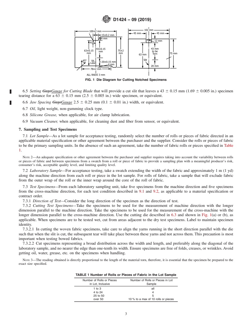
6.3 Cutting Die having essentially the shape and dimensions shown in Fig. 1(a) or (b). Either die provides the basic rectangular
test specimen 100 6 2 mm (4 6 0.05 in.) long by 63 6 0.15 mm (2.5 6 0.005 in.) wide, along with additional fabric at the top
edge of the specimen to help ensure the bottom portion of specimen will be torn during the test. The critical dimension of the test
specimen is the distance 43.0 6 0.15 mm (1.696 (1.69 6 0.005 in.) which is to be torn during the test.
NOTE 1—The improved die model shown in Fig. 1(a) has two new features not found in the original model, Fig. 1(b), namely a cutout for the bottom
of the specimen to aid in centering it in the clamps, and (optional) provision for cutting the 20.0 mm (0.75 in.) slit prior to inserting the specimen in the
tester. These dies can be made to order by most die manufacturers.
6.4 Air Pressure Regulator, capable of controlling gagegauge air pressure between 410 kPa and 620 kPa (60 psi and 90 psi),
when applicable, for air clamps.
Apparatus is commercially available.
D1424 − 09 (2019)
FIG. 1 Die Diagram for Cutting Notched Specimens
6.5 Setting GageGauge for Cutting Blade that will provide a cut slit that leaves a 43 6 0.15 mm (1.69 6 0.005 in.) specimen
tearing distance for a 63 6 0.15 mm (2.5 6 0.005 in.) wide specimen, or equivalent.
6.6 Jaw Spacing GageGauge 2.5 6 0.25 mm (0.1 6 0.01 in.) width, or equivalent.
6.7 Oil, light weight, non-gumming clock type.
6.8 Silicone Grease, when applicable, for air clamp lubrication.
6.9 Vacuum Cleaner, when applicable, for cleaning dust and fiber from sensor, or equivalent.
7. Sampling and Test Specimens
7.1 Lot Sample—As a lot sample for acceptance testing, randomly select the number of rolls or pieces of fabric directed in an
applicable material specification or other agreement between the purchaser and the supplier. Consider the rolls or pieces of fabric
to be the primary sampling units. In the absence of such an agreement, take the number of fabric rolls or pieces specified in Table
1.
NOTE 2—An adequate specification or other agreement between the purchaser and supplier requires taking into account the variability between rolls
or pieces of fabric and between specimens from a swatch from a roll or piece of fabric to provide a sampling plan with a meaningful producer’s risk,
consumer’s risk, acceptable quality level, and limiting quality level.
7.2 Laboratory Sample—For acceptance testing, take a swatch extending the width of the fabric and approximately 1 m (1 yd)
along the machine direction from each roll or piece in the lot sample. For rolls of fabric, take a sample that will exclude fabric
from the outer wrap of the roll or the inner wrap around the core of the roll of fabric.
7.3 Test Specimens—From each laboratory sampling unit, take five specimens from the machine direction and five specimens
from the cross-machine direction, for each test condition described in 9.1 and 9.2, as applicable to a material specification or
contract order.
7.3.1 Direction of Test—Consider the long direction of the specimen as the direction of test.
7.3.2 Cutting Test Specimens—Take the specimens to be used for the measurement of machine direction with the longer
dimension parallel to the machine direction. Take the specimens to be used for the measurement of the cross-machine with the
longer dimension parallel to the cross-machine direction. Use the cutting die described in 6.3 and shown in Fig. 1(a) or (b), as
applicable. When specimens are to be tested wet, cut from areas adjacent to the dry test specimens. Label to maintain specimen
identity.
7.3.2.1 In cutting the woven fabric specimens, take care to align the yarns running in the short direction parallel with the die
such that when the slit is cut, the subsequent tear will take place between these yarns and not across them. This precaution is most
important when testing bowed fabrics.
7.3.2.2 Cut specimens representing a broad distribution across the width and length, and preferably along the diagonal of the
laboratory sample, and no nearer the edge than one-tenth its width. Ensure specimens are free of folds, creases, or wrinkles. Avoid
getting oil, water, grease, etc. on the specimens when handling.
NOTE 3—The reading obtained is directly proportional to the length of the material torn, therefore, it is essential that the specimen be prepared to the
exact size specified.
TABLE 1 Number of Rolls or Pieces of Fabric in the Lot Sample
Number of Rolls or Pieces Number of Rolls or Pieces in Lot
in Lot, Inclusive Sample
1 to 3 all
4 to 24 4
25 to 50 5
over 50 10 % to a max of 10 rolls or pieces
D1424 − 09 (2019)
8. Preparation of Apparatus and Calibration
8.1 Select test instrument force range, such that the tear occurs between 20 and 80 % or 20 and 60 % of the full-scale range
as applicable. Ensure the clamps are spaced as directed in A1.4.
NOTE 4—For standard test apparatus, the useable portion of the full scale force range is 20 to 80 %. For the high capacity test instrument, the useable
portion of the full scale force range is 20 to 60 %.
8.2 When equipped with a registering sensor, examine the scale and the complementary sensor, as applicable. Using care and
without touching the sensor, vacuum away any loose fibers and dust.
8.3 Examine the knife edge for sharpness, wear, and central alignment as directed in A1.5 – A1.7.
8.4 For air clamps, set the air gagegauge pressure to the clamps to about 550 kPa (80 psi).
8.4.1 Maximum gagegauge pressure should be no more than 620 kPa (90 psi) and minimum gagegauge pressure no less than
410 kPa (60 psi).
8.5 When using microprocessor automatic data gathering systems, set the appropriate parameters as defined in the
manufacturer’s instructions.
8.6 Verify the calibration of the selected pendulum full scale force range using the procedure described in Annex A2, unless
otherwise specified.
9. Conditioning
9.1 Condition 1,
...
Questions, Comments and Discussion
Ask us and Technical Secretary will try to provide an answer. You can facilitate discussion about the standard in here.