

ASTM F3529-21
(Guide)Guide for Additive Manufacturing - Design - Material Extrusion of Polymers
General Information
- Abstract
SCOPE
1.1 This document specifies the features of MEX/P and provides detailed design recommendations.
1.2 Some of the fundamental principles are also applicable to other AM processes, provided that due consideration is given to process-specific features.
1.3 This document also provides a state of the art review of design guidelines associated with the MEX/P by bringing together relevant knowledge about this process and by supplementing the scope of ISO/ASTM 52910.
1.4 This international standard was developed in accordance with internationally recognized principles on standardization established in the Decision on Principles for the Development of International Standards, Guides and Recommendations issued by the World Trade Organization Technical Barriers to Trade (TBT) Committee.
- Status
- Published
- Publication Date
- 31-Oct-2021
- Technical Committee
- F42 - Additive Manufacturing Technologies
- Drafting Committee
- F42.04 - Design
Overview
ASTM F3529-21: Guide for Additive Manufacturing - Design - Material Extrusion of Polymers is a globally recognized standard developed by ASTM International. This guide presents detailed design recommendations for the additive manufacturing (AM) process known as Material Extrusion of Polymers (MEX/P). With the rise of 3D printing across various industries, this standard fills a crucial gap by providing comprehensive guidelines for designing parts to be produced using polymer extrusion technologies. It supports practitioners-including design and production engineers-in understanding the features, possibilities, and limitations of MEX/P compared to conventional processes like machining and injection molding.
Key Topics
- Fundamental Features of MEX/P: The standard covers unique characteristics of the MEX/P process, including bead deposition, layer-by-layer build-up, toolpath and infill patterns, and bonding between extruded layers and beads.
- Design Recommendations: Offers best practices related to part orientation, infill density, minimum wall thickness, overhangs, support structures, voids, and stair-step effects to optimize part performance and manufacturability.
- Process-Specific Guidelines: Addresses considerations for different machine configurations, feedstock types, and multi-material capabilities.
- Support for Complex Geometries: Provides guidance for designing intricate, multi-component assemblies, integrating positive and negative features, and utilizing cellular or lattice structures.
- Dimensional Accuracy and Surface Quality: Discusses the impact of build parameters like nozzle size and layer thickness on tolerances, finish, and post-processing needs.
- Material Considerations: Includes information on compatible thermoplastic materials, anisotropy in mechanical properties, and the effects of process settings on material performance.
Applications
Material Extrusion of Polymers is widely used for:
- Rapid Prototyping: Efficiently producing functional prototypes with complex geometries or intricate internal features for engineering validation.
- Tooling and Manufacturing Aids: Fabricating custom jigs, fixtures, and forming tools, reducing lead times and costs compared to conventional manufacturing.
- End-Use Parts: Manufacturing short runs of parts with complex or customized features, ideal for industries like automotive, aerospace, healthcare, and consumer goods.
- Educational and Research Applications: Providing a flexible platform for experimentation with geometry, materials, and part consolidation strategies.
Practicing the design guidelines in ASTM F3529-21 helps organizations harness the full potential of MEX/P, improving part quality, reducing material waste, and optimizing production costs and timescales.
Related Standards
ASTM F3529-21 complements and extends the scope of several international additive manufacturing standards, including:
- ISO/ASTM 52910: Additive manufacturing - Design - Requirements, guidelines, and recommendations
- ISO/ASTM 52900: General principles - Terminology
- ISO/ASTM 52903-1 and 52903-2: Material extrusion-based additive manufacturing - Feedstock materials and process equipment
- ISO/ASTM 52901: Requirements for purchased AM parts
- ISO/ASTM 52915: Specifications for Additive Manufacturing File Format (AMF)
- ISO/ASTM 52921: Terminology for coordinate systems and test methodologies
Additionally, VDI 3405 (part 3) provides design rules for part production using laser sintering and laser beam melting, which share some underlying principles with MEX/P.
Practical Value
By adhering to ASTM F3529-21, organizations and engineers can:
- Enhance part quality and functionality by designing specifically for material extrusion processes.
- Identify potential challenges in manufacturability early in the design phase.
- Reduce trial-and-error and material waste by following established best practices.
- Improve collaboration and communication across teams by using standardized terminology and definitions.
- Accelerate product development cycles and lower production costs, especially for custom or low-volume applications.
Understanding and applying the recommendations in ASTM F3529-21 is essential for anyone involved in additive manufacturing design for polymer extrusion, from product designers to production engineers and research professionals.
Get Certified
Connect with accredited certification bodies for this standard

DVS-ZERT GmbH
German welding certification society.
CARES (UK Certification Authority for Reinforcing Steels)
UK certification for reinforcing steels and construction.
EWF/IIW (European/International Welding Federation)
International welding personnel certification.
Sponsored listings
Frequently Asked Questions
ASTM F3529-21 is a guide published by ASTM International. Its full title is "Guide for Additive Manufacturing - Design - Material Extrusion of Polymers". This standard covers: SCOPE 1.1 This document specifies the features of MEX/P and provides detailed design recommendations. 1.2 Some of the fundamental principles are also applicable to other AM processes, provided that due consideration is given to process-specific features. 1.3 This document also provides a state of the art review of design guidelines associated with the MEX/P by bringing together relevant knowledge about this process and by supplementing the scope of ISO/ASTM 52910. 1.4 This international standard was developed in accordance with internationally recognized principles on standardization established in the Decision on Principles for the Development of International Standards, Guides and Recommendations issued by the World Trade Organization Technical Barriers to Trade (TBT) Committee.
SCOPE 1.1 This document specifies the features of MEX/P and provides detailed design recommendations. 1.2 Some of the fundamental principles are also applicable to other AM processes, provided that due consideration is given to process-specific features. 1.3 This document also provides a state of the art review of design guidelines associated with the MEX/P by bringing together relevant knowledge about this process and by supplementing the scope of ISO/ASTM 52910. 1.4 This international standard was developed in accordance with internationally recognized principles on standardization established in the Decision on Principles for the Development of International Standards, Guides and Recommendations issued by the World Trade Organization Technical Barriers to Trade (TBT) Committee.
ASTM F3529-21 is classified under the following ICS (International Classification for Standards) categories: 25.030 - Additive manufacturing. The ICS classification helps identify the subject area and facilitates finding related standards.
ASTM F3529-21 is available in PDF format for immediate download after purchase. The document can be added to your cart and obtained through the secure checkout process. Digital delivery ensures instant access to the complete standard document.
Standards Content (Sample)
This international standard was developed in accordance with internationally recognized principles on standardization established in the Decision on Principles for the
Development of International Standards, Guides and Recommendations issued by the World Trade Organization Technical Barriers to Trade (TBT) Committee.
Designation: F3529 − 21
Guide for
Additive Manufacturing — Design — Material Extrusion of
Polymers
This standard is issued under the fixed designation F3529; the number immediately following the designation indicates the year of
original adoption or, in the case of revision, the year of last revision. A number in parentheses indicates the year of last reapproval. A
superscript epsilon (´) indicates an editorial change since the last revision or reapproval.
INTRODUCTION
Polymer material extrusion (MEX/P) describes an additive manufacturing (AM) process and offers
anadditionalmanufacturingoptionalongsideestablishedprocesses.ApplicationsforMEXrangefrom
functional prototypes to simple fixtures and jigs to complex manufacturing aids and short manufac-
turing runs of parts with complex geometry. MEX has the potential to reduce manufacturing time and
costs,increasepartfunctionality,andhasthecapabilityofproducingverylargeparts.Practitionersare
aware of the strengths and weaknesses of conventional, long-established manufacturing processes,
suchascutting,joiningandshapingprocesses(forexample,bymachining,plasticweldingorinjection
molding) and of giving them appropriate consideration at the design stage and when selecting the
manufacturing process. In the case of MEX/PandAM in general, design and manufacturing engineers
only have a limited pool of experience. Without the limitations associated with conventional
processes, the use of MEX offers designers and manufacturers a high degree of freedom and this
requires an understanding about the possibilities and limitations of the process.
Note that the term Fused Filament Fabrication (FFF) is sometimes used to specify the type of MEX
process described in this document that refers to the extrusion of a thermoplastic filament in a layer.
The term MEX will be used in this document, or MEX/P when it is desired to emphasize the
deposition of polymer material, including thermoplastics, and other materials.
This document provides support to technology users, such as design and production engineers,
when designing parts that need to be manufactured by means of MEX/P. It will help practitioners to
explore the benefits of MEX/P processes and to recognize the process-related limitations when
designing parts. It also builds on ISO/ASTM 52910 to extend the requirements, guidelines and
recommendations for AM design to include the MEX/P process.
1. Scope ization established in the Decision on Principles for the
Development of International Standards, Guides and Recom-
1.1 This document specifies the features of MEX/P and
mendations issued by the World Trade Organization Technical
provides detailed design recommendations.
Barriers to Trade (TBT) Committee.
1.2 Some of the fundamental principles are also applicable
to other AM processes, provided that due consideration is 2. Referenced Documents
given to process-specific features.
2.1 ASTM Standards:
1.3 This document also provides a state of the art review of
F3413 Guide for Additive Manufacturing — Design —
design guidelines associated with the MEX/P by bringing
Directed Energy Deposition
together relevant knowledge about this process and by supple-
2.2 ISO/ASTM Standards:
menting the scope of ISO/ASTM 52910.
52900 Additive manufacturing — General principles —
Terminology
1.4 This international standard was developed in accor-
52901 Additive manufacturing — General principles —
dance with internationally recognized principles on standard-
Requirements for purchased AM parts
This guide is under the jurisdiction of ASTM Committee F42 on Additive
Manufacturing Technologies and is the direct responsibility of Subcommittee For referenced ISO/ASTM standards, visit the ASTM website, www.astm.org,
F42.04 on Design. orcontactASTMCustomerServiceatservice@astm.org.For Annual Book of ASTM
Current edition approved Nov. 1, 2021. Published February 2022. DOI: 10.1520/ Standards volume information, refer to the standard’s Document Summary page on
F3529-21. the ASTM website.
Copyright © ASTM International, 100 Barr Harbor Drive, PO Box C700, West Conshohocken, PA 19428-2959. United States
F3529 − 21
52903-1 Additive manufacturing — Material extrusion- 3.3 downskin angle, δ,n—angle between the plane of the
based additive manufacturing of plastic materials — Part buildplatformandthe downskin area(3.4)wherethevaluelies
1: Feedstock materials between 0° (parallel to the build platform) and 90° (perpen-
52903-2 Additive manufacturing — Material extrusion- dicular to the build platform).
based additive manufacturing of plastic materials — Part
3.3.1 Discussion—See Fig. 1.
2: Process equipment
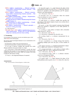
3.4 downskin area, D, n—(sub-)area where the normal
52910 Additive manufacturing — Design — Requirements,
vector in relation to z-axis is negative.
guidelines and recommendations
3.4.1 Discussion—See Fig. 1.
52915 Specification forAdditive Manufacturing File Format
3.5 infill density, n—a process variable that specifies the
(AMF) Version 1.2
percentage of the interior regions of part cross sections that is
52921 Terminology for additive manufacturing — Coordi-
filled with beads (3.2)
nate systems and test methodologies
3.6 nozzle, n—tip of the material extrusion head through
52950 Additive manufacturing — General principles —
which the material is deposited on the build platform or
Overview of data processing.
3 previous beads.
2.3 VDI Standard:
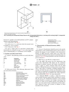
VDI 3405: Part 3: 2015 Additive manufacturing processes, 3.7 overhang, n—part surface or feature with a downskin
angle between 0° and 90°.
rapid manufacturing - Design rules for part production
using laser sintering and laser beam melting 3.7.1 Discussion—See Fig. 2a.
3.7.2 Discussion—Synonym for downskin area.
3. Terminology
3.8 overhang length, a, n—distance measurement for an
For the purposes of this document, the terms and definitions given in ISO/
overhang.
ASTM 52900 and the following apply.
3.8.1 Discussion—See Fig. 2a.
ISO and IEC maintain terminological databases for use in standardization at the
3.9 part consolidation, n—a design strategy that involves
following addresses:
combining multiple parts into one part, or fewer number of
— IEC Electropedia: available at http://www.electropedia.org/ parts.
— ISO Online browsing platform: available at http://www.iso.org/obp
3.10 support structure, n—sacrificial material that is depos-
3.1 air gap—a process variable that specifies the scalar
ited to support part material in subsequent layers.
distance between successive beads in a layer.
3.11 unsupported bridge, n—part surface or feature with a
3.1.1 Discussion—If the bead spacing is exactly the bead
downskin angle of 0° that is supported on both sides.
width,thentheairgapis0.Anairgapgreaterthan0meansthat
3.11.1 Discussion—See Fig. 2b.
neighboring beads do not touch, while an air gap of less than
0 indicates that beads overlap.
3.12 unsupported bridge width, w, n—distance measure-
ment for an unsupported bridge.
3.2 bead, n—the deposited filament of material.
3.12.1 Discussion—See Fig. 2b.
3.13 upskin angle, υ,n—angle between the plane of the
build platform and an upskin area (3.14) where the value lies
VDI - The Association of German Engineers; available online.
Reproduced with permission of the Verein Deutscher Ingenieure e. V.
Source: VDI 3405: Part 3:2015.
FIG. 1 Upskin and Downskin Areas U and D, Upskin and Downskin Angles υ and δ, Normal Vector nW
F3529 − 21
Reproduced with permission of the Verein Deutscher Ingenieure e. V.
Source: VDI 3405 Part 3:2015
FIG. 2 Overhang and Unsupported Bridge Features with Corresponding Dimensions a) overhang with overhang length b) unsupported
bridge with width w
between 0° (parallel to the build platform) and 90° (perpen-
PPSU polyphenylene sulfone
STL stereolithography format or surface
dicular to the build platform).
tessellation language
3.13.1 Discussion—See Fig. 1.
T glass transition temperature
g
3.14 upskin area, U, n—(sub-)area where the normal vector
in relation to z-axis is positive. 5. Characteristics of Material Extrusion (MEX)
3.14.1 Discussion—See Fig. 1.
Processes
3.15 void, n—empty space in a part that is formed either
5.1 General—Consideration should be given to the specific
intentionally, by setting the air gap (3.1) to a value larger than
characteristics of the manufacturing process used in order to
zero, or unintentionally as a consequence of the toolpath.
optimize the design of a part. Examples of the characteristic
features of MEX processes which need to be taken into
4. Symbols and Abbreviated Terms
considerationduringthedesignandprocessplanningstagesare
4.1 Symbols—The following symbols are used in this docu-
listed in 5.2 to 5.10. Design guidelines and rules-of-thumb are
ment:
given in Section 6.
Symbol Designation Unit
a overhand length mm
5.2 MEX Process and Machine Configurations:
D downskin area mm
5.2.1 The MEX AM process has the characteristic that
normal vector —
nW
Ra mean roughness µm
creates three dimensional (3D) objects by the continuous
w unsupported bridge mm
deposition of polymer material with relative movement be-
width
U upskin area mm
tween a single or various extrusion heads and the build
δ downskin angle °
platform.Although this process is being used to create objects
υ upskin angle °
with a wide range of materials, including biological cells,
4.2 Abbreviated Terms—The following abbreviated terms
cement, and food, the most common are thermoplastic mate-
are used in this document:
rials.These are liquefied by increasing their temperature inside
3D three dimensional
the extrusion head and re-solidified after being deposited.
ABS acrylonitrile butadiene styrene
Refer to ISO/ASTM 52903-1 for more information.
AM additive manufacturing
AMF additive manufacturing file format
5.2.2 Although MEX/P is usually a single-step process,
CAD computer aided design
some available materials require further operations to consoli-
CTE coefficient of thermal expansion
MEX/P material extrusion of polymers
date the part to the fundamental properties of the intended
MRI magnetic resonance imaging
material (metallic or ceramic); for example, removing of the
PA polyamide
PBF powder bed fusion
polymer as carrier of the metallic particles and sintering. In
PEEK polyether ether ketone
these cases, the specific design considerations of these opera-
PEKK polyetherketoneketone
tions should be taken into account in addition to those
PLA polyactic acid
PP polypropylene
described in this document.
F3529 − 21
5.2.3 Some machines allow the extrusion of multiple mate- the contact area increases between the deposited bead and the
rials in the same build cycle. This usually enables the use of a previous layer which results in better bonding and a denser,
different material for the object and the support structures (see stronger part.
5.8.4). 5.3.3 Bead Bonding:
5.2.4 Most MEX systems are based on a 3-axis
5.3.3.1 Bonding between filaments greatly influences part
configuration, and therefore base the building of objects by the
strength and stiffness. It should be recognized that bonding
sequential deposition of planar layers parallel to the build
occurs between neighboring beads in a layer, as well as
platform.However,somemachineconfigurationsincludemore
layer-to-layer.
axes, allowing the deposition of material in layers non-parallel
5.3.3.2 Bond strength is highly dependent on processing
to the build platform, or even non-planar layers.
conditions; all of the process variables mentioned in the
5.2.5 For most MEX systems, feedstock material is in the
filament deposition discussion apply. The local temperature
form of a filament and the extrusion head softens or partially
history controls the degree of bonding between beads. When
melts the filament and extrudes it at a much smaller diameter.
the temperature remains above the material’s softening tem-
In some systems, the feedstock consists of pellets (that is,
perature (typically the material’s glass transition temperature,
feedstock for injection molding). In this case, the extrusion
T )foraperiodoftime,thepolymermoleculesinthebeadscan
g
head is larger and more sophisticated since it liquifies the
start to intermingle forming a bond. If the local temperature
pellets and produces a filament that is much smaller than the
decreases too rapidly, weak bonds form between beads. A
pellet size.
balance between material deposition rate, extruder
5.2.6 Different MEX systems have different methods of
temperature, local part shape, and build chamber temperature
controllingthethermalenvironmentofthebuildvolume.Some
(if applicable) can achieve local temperatures that result in
systems are open to the environment and have a platform
strongbonds,whilepreservinglocalpartshape.Iftemperatures
heater. Others have an enclosed build volume, while others
are too high for too long, the material will flow, resulting in
incorporate a heater into the enclosure.
part or feature deformation.
5.3.4 Toolpath and Infill Patterns:
5.3 MEX Processing Fundamentals:
5.3.4.1 Typical toolpath patterns use a combination of
5.3.1 General—An understanding of MEX process funda-
contourandinfillpatterns.Often,onecontourwillbedeposited
mentals is important to understand part characteristics and the
to provide the outline of the part cross section, then the cross
advantages and disadvantages of MEX processes. The basics
section will be filled with a set of parallel deposits at a
offilamentdeposition,bonding,andtoolpathandinfillpatterns
prescribed angle, called infill. These infill beads are often
will be described in this section.
defined at specific angles to the platform’s X axis.An example
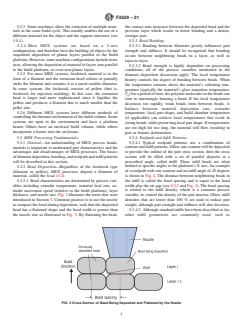
5.3.2 Bead Deposition—Regardless of the feedstock type
of a toolpath with one contour and an infill angle of 45 degrees
(filament or pellets), MEX processes deposit a filament of
is shown in Fig. 4. The distance between neighboring beads in
material, called the bead (3.2).
the infill is called the bead spacing and is equal to the bead
5.3.2.1 Bead characteristics are determined by process vari-
width plus the air gap (see 5.3.2 and Fig. 3). The bead spacing
ables including extruder temperature, material feed rate, ex-
truder movement speed (relative to the build platform), layer is related to the infill density, which is a common process
variable, to control the density of the part interior. Often, infill
thickness, and nozzle size. Fig. 3 illustrates the terms that were
introduced in Section 3. Common practice is to use the nozzle densities that are lower than 100 % are used to reduce part
weight, although part strength and stiffness will also decrease.
to compact the bead during deposition, such that the deposited
bead has a flattened shape and the bead width is greater than 5.3.4.2 Although standard infills have been described so far,
the nozzle size as illustrated in Fig. 3. By flattening the bead, other infill geometries are commonly used, such as
FIG. 3 Cross Section of Bead Being Deposited and Flattened by the Nozzle
F3529 − 21
FIG. 4 Top View of a Toolpath Illustrating One Contour and Infill at an Angle of 45° with a Bead Spacing that Yields an Infill Density
Less than 100 %
honeycomb, rectangular mesh, or diagonal mesh. In particular, bead widths. In the transition region, a void is formed since the
infill angles are frequently alternated by 90 degrees in subse- region is too thin for an additional bead.
quentlayers.Forexample,a45°/-45°infillpatternisoftenused
5.3.4.5 The final characteristic is the voids that form be-
toprovideadiagonalmesh.A0°/90°alternatepatternproduces
tween beads from layer to layer. These voids were shown in
a rectangular mesh. Similarly, other angle combinations can be
Fig. 3 as the white areas between previously deposited beads
used, such as 30°/-60°, 15°/-75°, etc. The specific type of infill
and the bead being deposited. Flattened beads have shapes that
geometry can significantly affect part properties and introduce
are between ellipses and rectangles with rounded corners; their
directional dependence in these part properties beyond that
shapesdependonthematerialfeedrate,depositionrate,nozzle
normally seen related to build orientation. Additionally, some
diameter, and layer thickness.
curved infill vector styles, such as gyroid infills, are offered in
5.4 Size of Parts—The size of parts is limited by the
some pre-processing software.
working area/working volume of the MEX machine. An
5.3.4.3 ThreeothercharacteristicsofMEXtoolpathswillbe
enclosed build chamber will have a defined maximum part
illustrated. First, the typical contour+infill toolpath tends to
size.LargerformatMEXmachinescanhaveanopenbuildarea
leave voids between successive beads. Shown in Fig. 5a is a
that allows for very large parts. There should be consideration,
single contour and four infill beads, viewed in the XY plane,
however,thatinlargerpartstheshrinkageeffectfromCTEand
where each pair of infill beads results from the extruder head
the deposition time are larger, increasing the risk of a weak
performing a 180 degree turn. Slight overlaps (over-extrusion)
inter-layer bonding. Another important practical factor that
between the contour and infill beads are used to aid bonding
limits the maximal part size is the time and cost of production,
and reduce void size, but a limit exists on how much overlap
can be achieved before bulges or other defects occur at these having a direct relation to volume of the part and the bead size.
Largernozzleorlayerthickness,andthereforelargerbeadsize,
turnaround sites.
5.3.4.4 Thesecondcharacteristicistheresultofverynarrow reduce the time and cost of production, but there is a subse-
quent reduction of resolution. This is commonly counteracted
part regions, where the region thickness is not a multiple of
bead width. The schematic in Fig. 5b shows a narrow tapered in large-scale MEX by a machining post-process step to obtain
the detailed features. Cost of production can be minimized by
region that transitions from more than three bead widths to two
FIG. 5 Voids that Form in a Layer Between a) Infill and Contour Beads or in b) Narrow Regions of Parts
F3529 − 21
choosing build orientation in a way that allows reducing the 5.6.1.1 Part support by way of a secondary, sacrificial
volume of supports required. An orientation that increases the material, may be needed due to part geometry, build space
layer cross-section would minimize the time required as well, utilization, or both.
as with small cross-sections the deposition needs to slow down 5.6.1.2 Shrinkage,residualstressanddeformationcanoccur
to allow the beads to cool down before the next layer is
due to local temperature differences.
deposited. 5.6.1.3 The surface quality of AM parts is typically influ-
enced by the layer-wise build-up technique (stair-step effect).
5.5 Typical Advantages of the MEX Process:
Post-processing may be required to improve surface quality,
5.5.1 MEX processes can be advantageous for manufactur-
depending on the application.
ing parts where the following points are relevant:
5.6.1.4 Consideration should be given to deviations from
5.5.1.1 MEX processes can be scaled up in size for large
form, dimensional and positional tolerances of parts. A ma-
part fabrication, particularly if nozzle size is scaled up. The
chining allowance should be provided for post-production
size scale-up can be easier than for other AM processes.
finishing. Specified geometric tolerances can be achieved by
5.5.1.2 Parts with multiple polymers in a single part can be
precision post-processing.
produced.
5.6.1.5 Anisotropic characteristics typically arise due to the
5.5.1.3 Degrees of design freedom for parts are typically
layer-wise build-up and should be taken into account during
high. Limitations of conventional manufacturing processes do
part design and process planning.
not usually exist; designers do not need to consider:
5.6.1.6 Limited polymeric material selection, especially
(1) draft angles, rounds and fillets for injection molding,
when compared to traditional polymeric manufacturing pro-
(2) tool accessibility, and
cesses.
(3) undercuts.
5.6.1.7 Parts typically have some porosity due to the inabil-
5.5.1.4 A wide range of complex geometries can be
ity to completely fill cross-sections.
produced, such as
5.6.1.8 Material properties can differ from expected values
(1) free-form geometries, for example, organic structures,
known from other technologies like injection molding. Mate-
(2) topologically optimised structures,
rial properties can be influenced significantly by process
(3) infill structures, for example, honeycomb, sandwich
settings and control.
and mesh structures,
5.6.1.9 As in many manufacturing processes, MEX exhibits
(4) hollow structures, for example, unbroken spheres and
a trade-off between resolution and speed. Small layer thick-
honeycomb structures with skins.
nesses and deposition nozzles can be used to improve
5.5.1.5 The degree of part complexity is largely unrelated to
resolution, but will cause slower build speeds.
production costs.
5.6.1.10 The physical interaction between the nozzle and
5.5.1.6 The number of assembly and joining processes can
the deposited part make MEX more prone to failure when
be reduced through part consolidation or single-body construc-
producing complex geometries such as cellular structures.
tion.
5.6.1.11 Limited efficiency gains are realizable when build-
5.5.1.7 Relative simpler working principle compared to
ing multiple parts, or packing the build platform, compared to
other AM processes. This helps reduce the cost of this type of
other AM processes like PBF and binder jetting.
machine and knowledge required for operating them and the
5.7 Economic and Time Effıciency:
availability of a wide range of machine and material manufac-
5.7.1 Provided that the geometry permits a part to be placed
turers.
in the build space in such a way that it can be manufactured as
5.5.1.8 Relative low cost of the feedstock material and
cost-effectively as possible, various different criteria for opti-
machine cost compared to other AM processes.
mization are available depending on the number of units
5.5.1.9 Overall part characteristics can be selectively con-
planned.
figured by adjusting process parameters locally.
5.7.1.1 For most parts, feedstock cost generally is the factor
5.5.1.10 Reduction in lead times until part production.
that has the greatest impact on build costs.
5.5.1.11 Tools for thermoforming, composites lay-up, and
5.7.1.2 If the intention is to build concept parts not intended
other forming processes can be fabricated with MEX/P with a
for testing or end use, then using the least expensive feedstock
relative improvement in cost and lead time compared to
that can make the concept parts is generally the best first step
traditional machining processes.
to cost optimization.
5.5.1.12 Sacrificial support materials can be used to create
5.7.1.3 If a large number of units is to be produced, limited
geometriesandassembliesthatwouldbechallengingforsingle
benefits are achieved by building more than one part at one
material technologies. However, the use of support structures
time. Some machine operations (such as tip wipes, extruder
also has disadvantages (see 5.6).
changes, and material purges) can be optimized with packing
5.5.1.13 Robust neat and reinforced thermoplastic material
parts together, but overall time savings is limited. Part packing
options.
is most effectively used to create builds to optimize machine
5.6 Typical Disadvantages of the MEX Process:
utilization, such as planning builds so that jobs will change at
5.6.1 Certain disadvantages associated with MEX and typi- the beginning of a shift and at the end of a shift. If multiple
cally associated with AM processes should be taken into partsarefabricatedsimultaneously,thenthebuildspaceshould
consideration during product design. be used as efficiently as possible. Provided that the part
F3529 − 21
geometry permits such orientation, strategies for reorientation is, support structure provides a surface on which to deposit
and nesting should be utilized to maximize the available build material if previously deposited part material is not in that
space.
location. As a secondary purpose, support structure can help
5.7.1.4 Sacrificial material used to support parts adds cost prevent residual stress-induced warping.
relating to the support material itself and the post processing
5.8.4.2 Support structures are common in MEX processes
needed to remove the support material. These considerations
and can be generated for the downskin areas of a part. These
need to be taken into account when build space efficiency is
part areas depend on the overall build orientation of the part
being determined.
and the dimensions of the downskin surface. Fig. 8 shows
5.8 Feature Constraints: specific cases of overhangs that require support structures. In
Fig. 8a, the downskin angle is less than 45 degrees, measured
5.8.1 General—Since AM parts are built up in successive
layers, separation of features may occur at some stage of the from the horizontal, which often require supports. Note that 45
build.This depends on the part geometry and build orientation. degreesisatypicalthresholdvalue,butmaydependonspecific
5.8.2 Islands—Islands (I) are features that connect to form a printersandmaterials.InFig.8b,theoverhanglengthisgreater
part (P) only at a later stage of the build process. How this than a threshold (usually no more than several millimeters).
connection will occur should be taken into consideration at the
5.8.5 Support Removal—Support structures of parts fabri-
design stage. Parts that are stable in terms of their overall
cated by MEX have to be removed after production. Support
design can be unstable at some stage of the build process (see
structures can be removed mechanically and chemically.When
Fig. 6).
using soluble materials for support structure generation, the
5.8.3 Overhang:
supportstructurecanberemovedinasolution,typicallyheated
5.8.3.1 Areas with a downskin angle of 0° produce an
water and cleaning agent.When using non-soluble material for
overhang with length a (see Fig. 2a). Small overhangs do not
support structure generation, the support structures can be
needanyadditionalgeometryintheformofsupportstructures.
removed manually with tools.
In such cases, the projected area is self-supporting during
5.8.6 Stair-step Effect—Due to the layer-wise build-up, the
manufacturing.Thepermissiblevaluesfor awilldependonthe
3D geometry of the part becomes a stack of layers, where the
specific MEX process, the material and the process parameters
shape of each layer is a 2.5D projection of its sliced geometry.
used.
This yields discrete steps in the build direction. The resulting
5.8.3.2 Acloserlookatthebeadsalongthesurfaceprovides
error caused by deviation of this 2.5D image from the original
insight into downskin (overhang) angles and when support
geometry is described as the stair-step effect which is evident
structures are needed. Fig. 7 shows three walls with various
in Fig. 9. The extent of this is largely dependent on the layer
downskin angles of 90°, 70°, and 45°. At a 45°angle, beads
thickness as shown in Fig. 7.
deposited in subsequent layers overlap the bead in the previous
5.8.7 Wall Thickness:
layerbyonlyhalfofitswidth.Ifdownskinsurfacesoflessthan
5.8.7.1 A part needs to be of a certain thickness to be
45 degrees are attempted, the overlap between beads is even
less which can cause poor bonding between layers and sagging manufactured without any distortion or breakage. Part walls
of the surface. should be at least as thick as required to provide suitable
5.8.4 Support Structure: performance, while being manufacturable and maintaining
5.8.4.1 Support structures in MEX processes serve primar- suitable shapes after manufacture. Part warping and curling of
ilyasaprovisionalsupportforapieceunderconstruction.That corners are issues that come with designing very thin walls.
Reproduced with permission of the Verein Deutscher Ingenieure e. V.
Source: VDI 3405 Part 3:2015
FIG. 6 Islands l (left) Formed During the Construction of Parts
F3529 − 21
FIG. 7 Five-layer Walls that Form Overhangs of a) δ = 90° (no overhang), b) δ = 70°, and c) δ =45°
FIG. 8 Downskin Areas (Overhangs) That Require Support Structure
Additionally, with proper judgement of the minimum wall larger shapes and result in material being added to a part. In
thickness, the printing costs of the parts can be reduced. contrast, negative features, such as holes, gaps, grooves, slots,
5.8.7.2 Factors that determine minimum wall thickness
and pockets, indicate the absence or removal of material from
include the type of material extrusion process, the presence of a part. Design rules have been developed for designing both
constant physical forces such as gravity, and the loading the
positive and negative features, and will be discussed in 6.7.
part must bear when functioning. See 6.7.3 for more informa-
5.8.9 Downfacing Wedges and Knife-edges—A variation of
tion.Iftheparttobemanufacturedistoundergoconstantforce
islands can arise if downward facing protrusions extend below
or pressure, thicker walls ensure enough resistance to impact
walls or other features to which the protrusions are attached. If
and sufficient strength. With MEX/P printers, the layer thick-
these downward protrusions have sharp edges and these edges
ness and size of the deposited bead (a function of nozzle size)
are the lowest part of the feature, then these features can cause
play significant roles in determining the minimum wall thick-
build problems. A wedge and a sharp knife-edge feature are
ness and feature size.
shown in Fig. 10. To the right is a close-up of the knife-edge
5.8.8 Positive and Negative Features:
featureshowingthesupportstructuresurroundingthetipofthe
5.8.8.1 Awide variety of positive and negative features can
knife-edge (see 6.7.5).
be fabricated in MEX/Pprocesses, which is consistent with the
5.8.10 Static and Movable Assemblies and Joints:
shape complexity capabilities ofAM, in general. Such features
5.8.10.1 Rather than fabricate individual parts that are
can serve many purposes including as interfaces for adjacent
assembled post-fabrication, MEX can fabricate complete as-
parts, fastening features, stiffening structures, or to allow
sembliesofparts.Insomecases,itisbettertoconsolidateparts
access,acceptmatingfeatures,oraidlightweightinginthecase
of negative features. into one to provide enhanced part integrity. If parts need to be
removed or disassembled later, then a static assembly is
5.8.8.2 Ribs, bosses, gussets, and tabs are examples of
positive features since they refer to features that protrude from preferred. An example is a multi-part product housing, where
F3529 − 21
FIG. 9 Impact of Different Layer Thicknesses on the Stair-step Effect
FIG. 10 Downward Wedge and Knife-edge Features that will Likely Require Surround Supports
the housing pieces need to be disassembled and assembled, be removed from joint areas. More generally, moving assem-
enabling other parts to be assembled inside the housing. blies can be fabricated by MEX.
5.8.10.2 In many AM processes, it is possible to design 5.8.10.3 For some applications, kinematic joints can be
working mechanisms, that is, parts that move relative to one replaced by compliant joints to form a compliant mechanism
another, without the need for secondary assembly operations. whose members bend. Taken further, compliant mechanisms
Kinematic joints, such as pin, sliding and cam joints, can be can be designed where members are designed to bend in such
designed to enable relative motion between parts. In MEX a manner that input/output relationships can be achieved
processes, joints can provide motion if support structures can without discrete joint regions. Fig. 11 illustrates the ideas
FIG. 11 Example Linkages and Compliant Mechanisms
F3529 − 21
behind a conventional kinematic linkage, a linkage with 5.9 Dimensional, Form and Positional Accuracy:
compliant joint, and a compliant mechanism.
5.9.1 Typically, MEX/P cannot produce parts with the
5.8.11 Cellular Structures—MEX processes are capable of
tolerances that can be achieved with conventional tool-based
fabricating very sophisticated geometric constructions. The
manufacturing processes. For this reason, post-processing may
class of cellular structures, including rectangular and diagonal
be necessary to meet accuracy requirements. Post-processing
meshes, honeycombs, lattices, and foams, can be used to
may include subtractive manufacturing, surface finishing, ther-
design lightweight, porous structures. Honeycombs are typi-
mal processing, or other operations according to ISO/ASTM
cally based on 2D patterns that are built up in the vertical
52910.
direction. Lattices are composed of patterns of short beams.
5.9.2 The form accuracy is defined by the nozzle size and
Foams can be either open-cell or closed-cell, where closed cell
the layer thickness, as described in 5.3, while the machine
foams can be considered as generalized honeycombs, while
architecture and software that generate the toolpaths determine
open-cell foams are like lattices with complex-shapes struts,
the dimensional accuracy.
rather than simple cylindrical or square struts. Fig. 12 shows
examples of the three types of cellular structures or materials. 5.9.3 In this respect, it is particularly important to be aware
5.8.12 Warpage:
of and consider process parameters that will influence charac-
5.8.12.1 Warpage can affect large parts in MEX. This
teristics of the final part. For example, build orientation to
deformation is mainly due to the gradient of temperature
some extent determines the level of accuracy that can be
between the extruded filament and the envelope/room
achieved. Directionally dependent (anisotropic) shrinkage of
temperature, causing non-uniform shrinkage and bending.This
the part can occur due to the layer-wise build-up. As another
can cause the part to release from the build platform.Also, this
example,layer-wiseconsistencycanbeaffectedbythelocation
gradient is taking place between the extruded filament and
of the part on the build platform.
either the initial build platform or the previously deposited
5.10 Data Quality, Resolution, Representation:
material (more significant for large parts where the deposited
layer is colder). This effect is often experienced by printing
5.10.1 The use of AM requires 3D geometric data that is
ABS, PSU and semi crystalline polymers such as PP, PEEK
typically represented as a tessellated model, but other repre-
and PA. Materials with large CTE are also susceptible to
sentations can also be used including voxels or sliced layer
warpage due to shrinkage upon cooling.
representations. For tessellated data, files describe the surface
5.8.12.2 Warpage is a common problem for MEX parts,
geometryofapartasaseriesoftriangularmeshes.Thevertices
especially large ones. This deformation is mainly due to
of the triangles are defined using the right-hand rule and the
thermal contraction as the filament cools from melt tempera-
normal vector.
ture to the temperature of the envelope/room, bed, or previous
5.10.2 The STL file format has been the most widely used
layer. Because each layer cools at a different time, the
industry data exchange format. The AMF format, which is
shrinkage is non-uniform and can cause bending of the part,
defined in ISO/ASTM 52915, was published to address the
particularly in the bottom corners where the stress of each
specific needs of additive manufacturing applications. It has
added layer accumulates. If severe, warping can cause the part
more robust support for tessellated data, including the
to release from the build platform which will result in a failed
description, location and orientation of objects, multi-
part.
componentobjects,andassembliesofobjects.The3MFformat
5.8.12.3 The degree of warping is highly dependent on
is also available for use in data exchange.
material type and is significantly worse in materials with high
5.10.3 Additional information can be found in ISO/ASTM
coefficients of thermal expansion such as ABS, high print
temperatures such as PPSU, or semi-crystalline polymers such 52950, Overview of data processing, the general design guide
ISO/ASTM 52910, and the directed energy deposition design
PP, PEEK, and PA(since crystallization is an additional source
of contraction). guide, ASTM F3413.
FIG. 12 Example Cellular Structures a) honeycomb, b) metal foam (1), c) lattice
F3529 − 21
6. Design Guidelines for Material Extrusion of Polymers and flat have lower strength and elongation properties. Vertical
(MEX/P) specimens exhibit significant reductions in properties com-
pared to horizontal specimens.
6.1 General—The design guidelines in this section take into
6.3.2 Some example studies will be summarized to indicate
account the specific characteristics of MEX/P. In general, the
the broader trends. For PEI (polyetherimide), tensile strength
MEX process in AM for polymers is similar to that for other
for flat specimens was found to be 21% less than for on edge
extrusion processes for polymers. This section describes the
specimens, while vertical specimens exhibited a reduction of
implications of build orientation, positioning and arrangement;
approximately 46 % (5). For elongation at break, reductions
material properties of fused polymers; surface characteristics
were 46 % and 73 %, respectively for flat and vertical
of fused polymers; aspects of post-production finishing and
specimens, compared to those on edge. Elastic modulus
other design considerations.
exhibited smaller reductions of 20 % for both flat and vertical
6.2 Material and Structural Characteristics:
specimens, compared to those on edge. These results are
6.2.1 Many different thermoplastics are available for
consistent with those reported by material vendors in their
MEX/P. Feedstocks can include filaments or pellets. Build
material data sheets. A study of PLA specimens demonstrated
spaces can be enclosed or open. Enclosed build spaces can be
even larger sensitivities to build orientation (6). The ultimate
heated to allow for better bonding between layers and less
tensile strength of on edge specimens was found to be 90 %
residual stress in parts. For unheated or open build spaces,
less for vertical specimens compared to on edge. Elongation at
consideration must be given to material type, layer thickness,
break was reduced by 50 % for flat versus on edge specimens,
and time elapsed between successive layers, as all of these
comparedtoareductionof90%forverticalspecimens.Elastic
parameters can affect bond-strength between layers.
modulus exhibited less variation, with a reduction of 43 % for
6.2.2 A selection of commonly available materials for
vertical specimens compared to those fabricated on edge.
MEX/P is shown in Table 1. Material data sheets are available
6.4 Build Orientation, Positioning and Arrangement:
from material suppliers and service bureaus.
6.4.1 General—The orientation, positioning and arrange-
6.2.3 Structural properties depend on a variety of factors,
ment of parts have a significant effect on part characteristics in
including anisotropy of the part, the type of polymer, degree of
MEX/P. The build orientation of the part should be agreed
feedstock recycling and processing conditions. In particular,
uponbetweenthecustomerandthepartproviderandshouldbe
the bond strength between successive layers has a significant
documented so it can be used for inspection, finishing, or
effect on structural properties, being lower typically than the
rework. The build orientation is recommended to follow the
bond strength intra-layer (3). Layer thickness, nozzle speed,
rules given in ISO/ASTM 52921.
nozzle temperature, time elapsed between successive layers,
6.4.2 Part Orientation:
andaheatedversusunheatedbuildspacecanhaveasignificant
6.4.2.1 Determining how to orient a part in the build
effectonbondstrength.Forthesereasons,itisdifficulttomake
chamber can involve complicated decisions and tradeoffs.
general statements about the achievable material structure and
Many types of part features are most accurate if built vertically
properties.
(walls, cylinders, bosses, holes). Slanted features can have
6.3 Mechanical Property Anisotropy:
rough surfaces. On the other hand, strength and stiffness
6.3.1 MEX/P parts generally have considerable anisotropy
considerations may dictate orientations that conflict with ori-
as a function of build orientation (4). A particularly high
entations preferred from accuracy or finish considerations. Part
anisotropy occurs between the build plane and the z-axis (z
regions that must be strong or stiff should be fabricated
direction). Strength and elongation at break in particular show
horizontally as discussed in the anisotropy section.
greater differences between orientations, while the modulus of
6.4.2.2 Additional considerations involve build time and
elasticity differs by considerably less. Many studies have
cost. Part orientations that minimize height (minimum number
shownthatthestrongestbuildorientationfortensilespecimens
of layers) can result in minimum build times. Furthermore,
is horizontal on edge, while tensile specimens built horizontal
certain part orientations may require additional support
structure, which can significantly increase build time and cost.
6.4.2.3 The designer will need to investigate several build
The boldface numbers in parentheses refer to a list of references at the end of
orientations to determine the best trade-off among possibly
this standard.
TABLE 1 Overview on Available Materials for MEX/P (Ref (2))
Polymer Feedstock Material Application Field Main Properties
Low temperature thermoplastics, for example, ABS, PLA (Semi-) rigid polymer parts Long-term usability
High performance polymers, for example, PEI, PEKK Rigid polymer parts Long-term usability with high loading; good chemical
resistance
High temperature polymers, for example, PPSU Rigid polymer parts, tooling Long-term usability with high loading and temperatures;
good chemical resistance
Semi-crystalline polymers, for example, PA6, PA12, PC (Semi-) rigid polymer parts Long-term usability; toughness
Filled polymers, for example, ABS-Carbon fiber, PA-Carbon High stiffness, wear resistant parts. Tooling. High stiffness
fiber
Filled amorphous polymers, for example, polymer-metal Metal complex parts Metal properties after de- binding and sintering
Elastomeric polymers, for example, TPU Elastic parts High elasticity, long term usability
Polymer-polymer blends, for example, PC-ABS Emerging applications Specialized applications
F3529 − 21
competing objectives.After part orientation is determined, it is roughness values due to the particularly pronounced stair-step
often possible to redesign some part features to improve their effect produced by the layer-wise build-up.
manufacturability or reduce the need for supports.
6.5.2 The presence of support structures also influences
6.4.3 Part Location in the Build Chamber: surfaceroughnessforthedownskinsurfacesthataresupported.
6.4.3.1 MEX/P is a thermal process and can be sensitive to Soluble support materials can result in somewhat smoother
surfaces, but this is dependent on feature geometry, surface
temperature variations in the build chamber. The thermal
environment surrounding a part being built can be different in angle, support material, and the time that the part is submerged
in the solvent. In contrast, break-away support structures tend
different locations. These thermal differences can be particu-
larlynotableforthosethermoplasticsthatareprocessedathigh to increase surface roughness since residual protrusions remain
after breaking away the supports.
temperatures, such as PEEK, PEKK, and PEI.
6.5.3 It is also possible to add a texture to part surfaces at
6.4.3.2 If the MEX machine has an enclosed build chamber,
it can be preheated to only a few degrees Celsius below the the design stage through a technique called image texturing.
Some software packages can be used to apply a textured image
glass transition temperature, Tg, of the material. This is ty
...