


ASTM C621-09(2018)
(Test Method)Standard Test Method for Isothermal Corrosion Resistance of Refractories to Molten Glass
Standard Test Method for Isothermal Corrosion Resistance of Refractories to Molten Glass
SIGNIFICANCE AND USE
3.1 This test method provides a rapid, inexpensive method for comparing the corrosion resistance of refractories. The isothermal conditions of this test method represent the most severe static corrosion environment possible at the specified test temperature. This test method is suitable for quality control, research and development applications, and for product value studies on similar materials. Tests run at a series of temperatures are often helpful in determining the use temperature limitations of a particular material. Melt-line corrosion results are also a useful indication of relative resistance to both upward and downward drilling corrosion mechanisms. Examination of test specimens also provides information about the tendency for a particular refractory to form stones or other glass defects.
3.2 Because this test method is both isothermal and static, and since most glass-contact refractories operate in a dynamic system with a thermal gradient, test results do not directly predict service in a furnace. The effects of differing thermal conductivities, refractory thickness, artificial cooling or insulation upon the refractory thermal gradient, and the erosive action of moving molten glass currents are not evaluated with this test.
SCOPE
1.1 This test method covers the determination of the corrosion resistance of refractories in contact with molten glass under static, isothermal conditions.
1.2 The values stated in inch-pound units are to be regarded as standard. The values given in parentheses are mathematical conversions to SI units that are provided for information only and are not considered standard.
1.3 This standard does not purport to address all of the safety concerns, if any, associated with its use. It is the responsibility of the user of this standard to establish appropriate safety, health, and environmental practices and determine the applicability of regulatory limitations prior to use.
1.4 This international standard was developed in accordance with internationally recognized principles on standardization established in the Decision on Principles for the Development of International Standards, Guides and Recommendations issued by the World Trade Organization Technical Barriers to Trade (TBT) Committee.
General Information
Buy Standard
Standards Content (Sample)
NOTICE: This standard has either been superseded and replaced by a new version or withdrawn.
Contact ASTM International (www.astm.org) for the latest information
Designation: C621 − 09 (Reapproved 2018)
Standard Test Method for
Isothermal Corrosion Resistance of Refractories to Molten
Glass
This standard is issued under the fixed designation C621; the number immediately following the designation indicates the year of
original adoption or, in the case of revision, the year of last revision. A number in parentheses indicates the year of last reapproval. A
superscript epsilon (´) indicates an editorial change since the last revision or reapproval.
1. Scope uct value studies on similar materials. Tests run at a series of
temperatures are often helpful in determining the use tempera-
1.1 This test method covers the determination of the corro-
ture limitations of a particular material. Melt-line corrosion
sion resistance of refractories in contact with molten glass
results are also a useful indication of relative resistance to both
under static, isothermal conditions.
upward and downward drilling corrosion mechanisms. Exami-
1.2 The values stated in inch-pound units are to be regarded
nation of test specimens also provides information about the
as standard. The values given in parentheses are mathematical
tendency for a particular refractory to form stones or other
conversions to SI units that are provided for information only
glass defects.
and are not considered standard.
3.2 Because this test method is both isothermal and static,
1.3 This standard does not purport to address all of the
and since most glass-contact refractories operate in a dynamic
safety concerns, if any, associated with its use. It is the
system with a thermal gradient, test results do not directly
responsibility of the user of this standard to establish appro-
predict service in a furnace. The effects of differing thermal
priate safety, health, and environmental practices and deter-
conductivities, refractory thickness, artificial cooling or insu-
mine the applicability of regulatory limitations prior to use.
lation upon the refractory thermal gradient, and the erosive
1.4 This international standard was developed in accor-
action of moving molten glass currents are not evaluated with
dance with internationally recognized principles on standard-
this test.
ization established in the Decision on Principles for the
Development of International Standards, Guides and Recom-
4. Apparatus
mendations issued by the World Trade Organization Technical
4.1 Glass-Melting Test Furnace, heated with some type of
Barriers to Trade (TBT) Committee.
electrical resistor (Note 1) and having a chamber large enough
2. Referenced Documents to receive four crucible assemblies of the type used in the test
(Fig. 1) is required. The zone of the furnace in which the
2.1 ASTM Standards:
crucibles will rest should possess a maximum transverse
E220 Test Method for Calibration of Thermocouples By
thermal gradient of 61.8 °F (61 °C). Fig. A1.1 shows a
Comparison Techniques
schematic drawing of a furnace that is satisfactory for this test.
3. Significance and Use
NOTE 1—It has been demonstrated that gas-fired furnaces show greater
variability and higher average corrosion with this test method and are
3.1 This test method provides a rapid, inexpensive method
therefore generally unsuitable.
for comparing the corrosion resistance of refractories. The
isothermal conditions of this test method represent the most 4.2 Temperature-Control Instrumentation, capable of main-
taining the desired temperature to 61.8 °F (61 °C).
severe static corrosion environment possible at the specified
test temperature. This test method is suitable for quality
4.3 Thermocouple, for use as the temperature measuring
control, research and development applications, and for prod-
device. The type of thermocouple chosen will depend on the
normal use temperature of the furnace. Since thermocouples
age with a consequent drift in the signal fed to the control
This test method is under the jurisdiction of ASTM Committee C08 on
instrument, check the couple before each test run with a
RefractoriesandisthedirectresponsibilityofSubcommitteeC08.10onRefractories
for Glass.
calibrated thermocouple. Test Method E220 specifies calibra-
Current edition approved Oct. 1, 2018. Published October 2018. Originally
tion procedures for thermocouples. If drift becomes severe,
approved in 1968. Last previous edition approved in 2014 as C621 – 09 (2014).
replace the thermocouple. Position the thermocouple hot junc-
DOI: 10.1520/C0621-09R18.
For referenced ASTM standards, visit the ASTM website, www.astm.org, or tion in the furnace to coincide with the level of the glass line
contact ASTM Customer Service at service@astm.org. For Annual Book of ASTM
of the test samples.
Standards volume information, refer to the standard’s Document Summary page on
the ASTM website. 4.4 Platinum Crucibles (Fig. 1).
Copyright © ASTM International, 100 Barr Harbor Drive, PO Box C700, West Conshohocken, PA 19428-2959. United States
C621 − 09 (2018)
the specimen on the surface opposite the font scar (and
perpendicular to this surface) and at least 3 in. (76 mm) from
an end and a side of the casting. For voidless castings, take the
specimenfromanycastsurfacenearthetop,saw-cutsurfaceof
the block. Take this specimen at least 3 in. from any corner of
the casting. Such specimens avoid edge and corner crystalli-
zation effects and have chemistries similar to those represent-
ing the bulk of the casting.
5.2 Specimen Size and Preparation:
5.2.1 The specimen shall be either 0.39 in. (9.9 mm) square
by 2.0 in. (51 mm) long or cylinders 0.5 in. (13 mm) in
diameter by 2.0 in. long. In either case, the specified dimen-
sions shall be controlled within 0.002 in. (0.05 mm) along the
entire length of the specimens.
5.2.2 Prepare cylindrical specimens with a diamond-core
bit. Specimens should be perfectly smooth (free of small
offsets, etc.) and free of metal marks from the drill along their
entire length. Grind square specimens to size, after diamond
sawing, on a diamond hone to provide clean parallel faces.
5.2.3 Do not grind the specimens with silicon carbide
because of the potential contaminating effect.
5.2.4 After grinding or drilling, dry the specimens to con-
stant weight at 230 °F (110 °C) prior to corrosion testing.
5.3 Pretest Specimen Measurements and Inspection:
5.3.1 Make a bulk density measurement on the specimen.
SI Equivalents
Calculate the volume of the specimen either from the specimen
in. mm
0.030 0.76 dimensions or by water displacement.
⁄64 5
5.3.2 Measure the specimen to the nearest 0.001 in.
⁄2 13
(0.03 mm) at two points, the anticipated glass line, and at a
⁄64 13
level halfway between the glass line and the bottom of the
⁄32 13
specimen. With square specimens, it is important that the
1 ⁄4 32.8
orientation of these measurements be marked above the glass
line so that corresponding measurements can be made after the
NOTE 1—All undesignated dimensions are in inches.
test.
FIG. 1 Crucible Assemblage
5.3.3 Make an inspection of the specimen prior to the test,
noting color, evidence of porosity, and any irregularities or
unusual features.
4.5 Sintered Zircon, or other refractory wafers (Annex A2).
5.4 Other Specimen Notes:
4.6 Zircon Cement (Annex A3).
5.4.1 Four or more specimens are usually tested concur-
4.7 Measuring Microscope.
rently. It has been found helpful to include a control (or
4.8 Tongs, suitable for handling samples in the furnace (Fig.
standard) in each series of specimens. Ideally, the control
A1.6).
specimens are taken from a single refractory block or shape
retained semi-permanently for that purpose. By using a control
4.9 Furnace, for preheating test specimens to about 1832 °F
specimen, the variability between tests can be continuously
(1000 °C) (Annex A1).
scrutinizedandthecontrolspecimencanserveasacomparison
4.10 Diamond Saw, and diamond hone, or diamond-core
standard for the other specimen in the same test.
drill.
5.4.2 Either round or square test specimens may be used,
but never both in the same series of experiments, since data
5. Test Specimens
from the two types of specimen geometry are not directly
5.1 Sample Selection—A sample shall be comprised of one
comparable.
or more specimens cut from the refractory unit being tested.
5.4.3 Specimen orientation within a test or series of tests
Specimens should be as representative of the material being
should be consistent.When applicable, cast or pressed surfaces
tested as possible. In the testing of slip-cast and pressed
should comprise the sample bottom.
refractory products, take care to avoid cracks, checks, obvious
contaminants, etc. In the testing of fusion-cast materials, it is
6. Test Temperature and Duration
recognized that wide variations in both chemistry and crystal
size occur within every casting.Therefore, a standard sampling 6.1 Test temperatures should simulate those in the intended
location should be used and specified. For flat-cast blocks, take service.
C621 − 09 (2018)
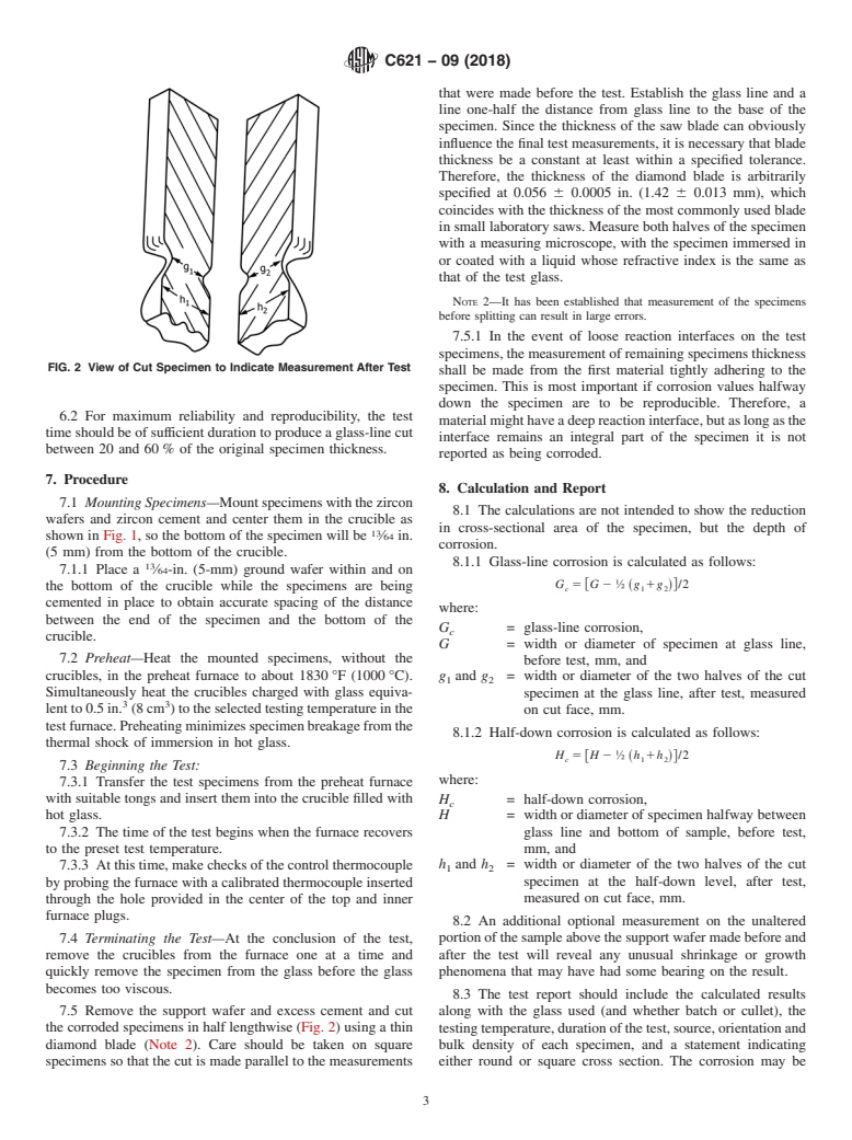
that were made before the test. Establish the glass line and a
line one-half the distance from glass line to the base of the
specimen. Since the thickness of the saw blade can obviously
influence the final test measurements, it is necessary that blade
thickness be a constant at least within a specified tolerance.
Therefore, the thickness of the diamond blade is arbitrarily
specified at 0.056 6 0.0005 in. (1.42 6 0.013 mm), which
coincides with the thickness of the most commonly used blade
in small laboratory saws. Measure both halves of the specimen
with a measuring microscope, with the specimen immersed in
or coated with a liquid whose refractive index is the same as
that of the test glass.
NOTE 2—It has been established that measurement of the specimens
before splitting can result in large errors.
7.5.1 In the event of loose reaction interfaces on the test
specimens, the measurement of remaining specimens thickness
FIG. 2 View of Cut Specimen to Indicate Measurement After Test
shall be made from the fir
...
This document is not an ASTM standard and is intended only to provide the user of an ASTM standard an indication of what changes have been made to the previous version. Because
it may not be technically possible to adequately depict all changes accurately, ASTM recommends that users consult prior editions as appropriate. In all cases only the current version
of the standard as published by ASTM is to be considered the official document.
Designation: C621 − 09 (Reapproved 2014) C621 − 09 (Reapproved 2018)
Standard Test Method for
Isothermal Corrosion Resistance of Refractories to Molten
Glass
This standard is issued under the fixed designation C621; the number immediately following the designation indicates the year of
original adoption or, in the case of revision, the year of last revision. A number in parentheses indicates the year of last reapproval. A
superscript epsilon (´) indicates an editorial change since the last revision or reapproval.
1. Scope
1.1 This test method covers the determination of the corrosion resistance of refractories in contact with molten glass under
static, isothermal conditions.
1.2 The values stated in inch-pound units are to be regarded as standard. The values given in parentheses are mathematical
conversions to SI units that are provided for information only and are not considered standard.
1.3 This standard does not purport to address all of the safety concerns, if any, associated with its use. It is the responsibility
of the user of this standard to establish appropriate safety safety, health, and healthenvironmental practices and determine the
applicability of regulatory limitations prior to use.
1.4 This international standard was developed in accordance with internationally recognized principles on standardization
established in the Decision on Principles for the Development of International Standards, Guides and Recommendations issued
by the World Trade Organization Technical Barriers to Trade (TBT) Committee.
2. Referenced Documents
2.1 ASTM Standards:
E220 Test Method for Calibration of Thermocouples By Comparison Techniques
3. Significance and Use
3.1 This test method provides a rapid, inexpensive method for comparing the corrosion resistance of refractories. The isothermal
conditions of this test method represent the most severe static corrosion environment possible at the specified test temperature. This
test method is suitable for quality control, research and development applications, and for product value studies on similar
materials. Tests run at a series of temperatures are often helpful in determining the use temperature limitations of a particular
material. Melt-line corrosion results are also a useful indication of relative resistance to both upward and downward drilling
corrosion mechanisms. Examination of test specimens also provides information about the tendency for a particular refractory to
form stones or other glass defects.
3.2 Because this test method is both isothermal and static, and since most glass-contact refractories operate in a dynamic system
with a thermal gradient, test results do not directly predict service in a furnace. The effects of differing thermal conductivities,
refractory thickness, artificial cooling or insulation upon the refractory thermal gradient, and the erosive action of moving molten
glass currents are not evaluated with this test.
4. Apparatus
4.1 Glass-Melting Test Furnace, heated with some type of electrical resistor (Note 1) and having a chamber large enough to
receive four crucible assemblies of the type used in the test (Fig. 1) is required. The zone of the furnace in which the crucibles
will rest should possess a maximum transverse thermal gradient of 61.8°F (61°C).61.8 °F (61 °C). Fig. A1.1 shows a schematic
drawing of a furnace that is satisfactory for this test.
NOTE 1—It has been demonstrated that gas-fired furnaces show greater variability and higher average corrosion with this test method and are therefore
generally unsuitable.
This test method is under the jurisdiction of ASTM Committee C08 on Refractories and is the direct responsibility of Subcommittee C08.10 on Refractories for Glass.
Current edition approved Sept. 1, 2014Oct. 1, 2018. Published November 2014October 2018. Originally approved in 1968. Last previous edition approved in 20092014
as C621 – 09.C621 – 09 (2014). DOI: 10.1520/C0621-09R14.10.1520/C0621-09R18.
For referenced ASTM standards, visit the ASTM website, www.astm.org, or contact ASTM Customer Service at service@astm.org. For Annual Book of ASTM Standards
volume information, refer to the standard’s Document Summary page on the ASTM website.
Copyright © ASTM International, 100 Barr Harbor Drive, PO Box C700, West Conshohocken, PA 19428-2959. United States
C621 − 09 (2018)
SI Equivalents
in. mm
0.030 0.76
⁄64 5
⁄2 13
⁄64 13
⁄32 13
1 25
1 ⁄4 32.8
NOTE 1—All undesignated dimensions are in inches.
FIG. 1 Crucible AssemblageAssemblage
4.2 Temperature-Control Instrumentation, capable of maintaining the desired temperature to 61.8°F (61°C).61.8 °F (61 °C).
4.3 Thermocouple, for use as the temperature-measuring temperature measuring device. The type of thermocouple chosen will
depend on the normal use temperature of the furnace. Since thermocouples age with a consequent drift in the signal fed to the
control instrument, check the couple before each test run with a calibrated thermocouple. Test Method E220 specifies calibration
procedures for thermocouples. If drift becomes severe, replace the thermocouple. Position the thermocouple hot junction in the
furnace to coincide with the level of the glass line of the test samples.
4.4 Platinum Crucibles (Fig. 1).
4.5 Sintered Zircon, or other refractory wafers (Annex A2).
4.6 Zircon Cement (Annex A3).
4.7 Measuring Microscope.
4.8 Tongs, suitable for handling samples in the furnace (Fig. A1.6).
4.9 Furnace, for preheating test specimens to about 1832°F (1000°C)1832 °F (1000 °C) (Annex A1).
4.10 Diamond Saw, and diamond hone, or diamond-core drill.
5. Test Specimens
5.1 Sample Selection—A sample shall be comprised of one or more specimens cut from the refractory unit being tested.
Specimens should be as representative of the material being tested as possible. In the testing of slip-cast and pressed refractory
products, take care to avoid cracks, checks, obvious contaminants, etc. In the testing of fusion-cast materials, it is recognized that
C621 − 09 (2018)
wide variations in both chemistry and crystal size occur within every casting. Therefore, a standard sampling location should be
used and specified. For flat-cast blocks, take the specimen on the surface opposite the font scar (and perpendicular to this surface)
and at least 3 in. (76 mm) from an end and a side of the casting. For voidless castings, take the specimen from any cast surface
near the top, saw-cut surface of the block. Take this specimen at least 3 in. from any corner of the casting. Such specimens avoid
edge and corner crystallization effects and have chemistries similar to those representing the bulk of the casting.
5.2 Specimen Size and Preparation:
5.2.1 The specimen shall be either 0.39 in. (9.9 mm) square by 2.0 in. (51 mm) long or cylinders 0.5 in. (13 mm) in diameter
by 2.0 in. long. In either case, the specified dimensions shall be controlled within 0.002 in. (0.05 mm) along the entire length of
the specimens.
5.2.2 Prepare cylindrical specimens with a diamond-core bit. Specimens should be perfectly smooth (free of small offsets, etc.)
and free of metal marks from the drill along their entire length. Grind square specimens to size, after diamond sawing, on a
diamond hone to provide clean parallel faces.
5.2.3 Do not grind the specimens with silicon carbide because of the potential contaminating effect.
5.2.4 After grinding or drilling, dry the specimens to constant weight at 230°F (110°C)230 °F (110 °C) prior to corrosion testing.
5.3 Pretest Specimen Measurements and Inspection:
5.3.1 Make a bulk density measurement on the specimen. Calculate the volume of the specimen either from the specimen
dimensions or by water displacement.
5.3.2 Measure the specimen to the nearest 0.001 in. (0.03 mm) (0.03 mm) at two points, the anticipated glass line, and at a level
halfway between the glass line and the bottom of the specimen. With square specimens, it is important that the orientation of these
measurements be marked above the glass line so that corresponding measurements can be made after the test.
5.3.3 Make an inspection of the specimen prior to the test, noting color, evidence of porosity, and any irregularities or unusual
features.
5.4 Other Specimen Notes:
5.4.1 Four or more specimens are usually tested concurrently. It has been found helpful to include a control (or standard) in each
series of specimens. Ideally, the control specimens are taken from a single refractory block or shape retained semi-permanently
for that purpose. By using a control specimen, the variability between tests can be continuously scrutinized,scrutinized and the
control specimen can serve as a comparison standard for the other specimen in the same test.
5.4.2 Either round or square test specimens may be used, but never both in the same series of experiments, since data from the
two types of specimen geometry are not directly comparable.
5.4.3 Specimen orientation within a test or series of tests should be consistent. When applicable, cast or pressed surfaces should
comprise the sample bottom.
6. Test Temperature and Duration
6.1 Test temperatures should simulate those in the intended service.
6.2 For maximum reliability and reproducibility, the test time should be of sufficient duration to produce a glass line glass-line
cut between 20 and 60 % of the original specimen thickness.
7. Procedure
7.1 Mounting Specimens—Mount specimens with the zircon wafers and zircon cement and center them in the crucible as shown
in Fig. 1, so the bottom of the specimen will be ⁄64 in. (5 mm) from the bottom of the crucible.
7.1.1 Place a ⁄64-in. (5-mm) ground wafer within and on the bottom of the crucible while the specimens are being cemented
in place to obtain accurate spacing of the distance between the end of the specimen and the bottom of the crucible.
7.2 Preheat—Heat the mounted specimens, without the crucibles, in the preheat furnace to about 1830°F (1000°C).1830 °F
3 3
(1000 °C). Simultaneously heat the crucibles charged with glass equivalent to 0.5 in. (8 cm ) to the selected testing temperature
in the test furnace. Preheating minimizes specimen breakage from the thermal shock of immersion in hot glass.
7.3 Beginning the Test:
7.3.1 Transfer the test specimens from the preheat furnace with suitable tongs and insert them into the
...
Questions, Comments and Discussion
Ask us and Technical Secretary will try to provide an answer. You can facilitate discussion about the standard in here.