


ASTM F408-99(2015)
(Test Method)Standard Test Method for Tires for Wet Traction in Straight-Ahead Braking, Using a Towed Trailer
Standard Test Method for Tires for Wet Traction in Straight-Ahead Braking, Using a Towed Trailer
SIGNIFICANCE AND USE
5.1 The measured values are traction properties of tires obtained with the towed trailer described here on a given road surface, under given environmental conditions (ambient and road surface temperature, humidity, wind speed and direction, purity and film depth of water used to wet the road surface). They are carried out in accordance with the stated test procedures and reflect the performance of the total tire-vehicle environmental system. A change in any of these factors may change the measurements on a subsequent run of the test.
5.2 These test methods are suitable for research and development purposes, where tires are compared during a single series of tests. They may not be suitable for regulatory statutes or specification acceptance, because the values obtained may not necessarily agree or correlate either in rank order or absolute traction performance level with those obtained on other road surfaces (or the same surface after additional wear), under other environmental conditions, or other towed trailers, or other test devices, or with results obtained with other test procedures.
SCOPE
1.1 This test method covers the measurement of braking traction of tires designed for passenger cars or light trucks. Such braking traction measurements are applicable to conditions wherein the vehicle is traveling straight ahead on a wet, paved surface.
1.2 The values stated in SI units are to be regarded as the standard. The values given in parentheses are for information only.
1.3 This standard does not purport to address all of the safety concerns, if any, associated with its use. It is the responsibility of the user of this standard to establish appropriate safety and health practices and determine the applicability of regulatory limitations prior to use.
General Information
Buy Standard
Standards Content (Sample)
NOTICE: This standard has either been superseded and replaced by a new version or withdrawn.
Contact ASTM International (www.astm.org) for the latest information
Designation: F408 − 99 (Reapproved 2015)
Standard Test Method for
Tires for Wet Traction in Straight-Ahead Braking, Using a
Towed Trailer
ThisstandardisissuedunderthefixeddesignationF408;thenumberimmediatelyfollowingthedesignationindicatestheyearoforiginal
adoptionor,inthecaseofrevision,theyearoflastrevision.Anumberinparenthesesindicatestheyearoflastreapproval.Asuperscript
epsilon (´) indicates an editorial change since the last revision or reapproval.
1. Scope 3.1.1 braking force, [F], n—of a tire, the negative longitu-
dinal force resulting from braking torque application. F538
1.1 This test method covers the measurement of braking
traction of tires designed for passenger cars or light trucks.
3.1.2 braking force coeffıcient, n—of a tire, the ratio of
Such braking traction measurements are applicable to condi-
braking force to normal force. F538
tions wherein the vehicle is traveling straight ahead on a wet,
3.1.3 braking force coeffıcient, peak, n—of a tire, the maxi-
paved surface.
mum value of tire braking force coefficient that occurs prior to
1.2 The values stated in SI units are to be regarded as the
wheel lockup as the braking torque is progressively increased.
standard. The values given in parentheses are for information
F538
only.
3.1.4 braking force coeffıcient, slide, n—of a tire, the value
1.3 This standard does not purport to address all of the
of braking force coefficient obtained on a locked wheel. F538
safety concerns, if any, associated with its use. It is the
2 2
3.1.5 braking torque, [ML /T ], n—of a vehicle, the
responsibility of the user of this standard to establish appro-
negative wheel torque. F538
priate safety and health practices and determine the applica-
bility of regulatory limitations prior to use.
3.1.6 lockup, n—of a wheel, the condition of a wheel in
which its rotational velocity about the wheel spin axis is zero
2. Referenced Documents
and it is prevented from rotating in the presence of applied
2.1 ASTM Standards:
wheel torque.
E274Test Method for Skid Resistance of Paved Surfaces
3.1.7 longitudinal force, [F], n—of a tire, the component of
Using a Full-Scale Tire
the tire force vector in the X' direction. F538
E1337Test Method for Determining Longitudinal Peak
Braking Coefficient of Paved Surfaces Using Standard 3.1.8 normal force, [F], n—of a tire,thecomponentofatire
Reference Test Tire force vector in the Z' direction. F538
F377PracticeforCalibrationofBraking/TractiveMeasuring
3.1.9 skid number (SN), n—slide braking force coefficient
Devices for Testing Tires
multiplied by 100. F538
F457Test Method for Speed and Distance Calibration of
3.1.10 test run, n—asinglepassofaloadedtireoveragiven
Fifth Wheel Equipped With Either Analog or Digital
test surface. F538
Instrumentation
F538Terminology Relating to the Characteristics and Per-
3.1.11 tire axis system, n—the origin of the tire-axis system
formance of Tires
is the center of the tire contact where the X'-axis is the
F1650Practice for Evaluating Tire Traction Performance
intersection of the wheel plane and the road plane with a
Data Under Varying Test Conditions
positive direction forward, the Z'-axis is perpendicular to the
road plane with a positive direction downward, and theY'-axis
3. Terminology
isintheroadplane,itsdirectionbeingchosentomaketheaxis
3.1 Definitions:
system orthogonal and right-hand.
3.1.11.1 Discussion—See Fig. 1. F538
This test method is under the jurisdiction of ASTM Committee F09 on Tires
and is the direct responsibility of Subcommittee F09.20 on Vehicular Testing. 3.1.12 tire forces, [F], n—theexternalforcesactingonatire
Current edition approved May 1, 2015. Published June 2015. Originally
by the road. F538
approved in 1975. Last previous edition approved in 2008 as F408–99 (2008).
DOI: 10.1520/F0408-99R15. 3.1.13 torque, [FL], n—of a wheel, the external torque
For referenced ASTM standards, visit the ASTM website, www.astm.org, or
applied to a tire from a vehicle about the wheel spin axis.
contact ASTM Customer Service at service@astm.org. For Annual Book of ASTM
3.1.13.1 Discussion—Driving torque is positive wheel
Standards volume information, refer to the standard’s Document Summary page on
the ASTM website. torque; braking torque is negative wheel torque. F538
Copyright © ASTM International, 100 Barr Harbor Drive, PO Box C700, West Conshohocken, PA 19428-2959. United States
F408 − 99 (2015)
6.2 Tow Vehicle:
6.2.1 Thetowvehicleshallhavethecapabilityoftowingthe
trailer at specified speeds in the range from 32 to 96 km/h (20
to 60 mph), which are to be kept constant to within 0.8 km/h
(0.5 mph), even at maximum level of application of braking
forces.
6.2.2 The tow vehicle shall be equipped with the following
accessories:
6.2.2.1 Equipment to actuate brakes on towed trailer,
6.2.2.2 A water tank to store sufficient water to supply the
watering system unless external watering is used,
6.2.2.3 Recording equipment to record signals from trans-
ducers installed on the towed trailer,
6.2.2.4 Hitch with adjustable height for towing the trailer,
and
6.2.2.5 Optionalequipmenttomonitorandcontrolbrakeline
pressure, brake application rate, and water application rate.
FIG. 1 Tire-Axis System
6.3 Towed Trailer—The trailer shall be equipped with a tow
hitch and one or two test wheels which shall be instrumented
as described. A self-watering system is optional (see 6.3.6).
3.1.14 vertical load, n—the normal reaction of the tire on
Trailers shall be designed to accommodate the range of
the road which is equal to the negative of the normal force.
passenger car and light truck rim sizes to be tested.
F538
6.3.1 Thehitchheightshallbenohigherthantheloadedtire
4. Summary of Test Method
radius, and the distance from hitch ball to axle centerline shall
be no less than ten times the hitch height. For external
4.1 The measurements are conducted on tires mounted on a
watering, the trailer hitch on the tow vehicle shall be so
trailer towed by a vehicle. Brakes are applied firmly until one
arranged that the trailer tires will run in tracks separate from
or both test tire(s) are locked and then held locked for a period
the tire tracks of the tow vehicle. The minimum track offset of
ofatleast1.5satspeedsrangingfrom32km/h(20mph)to96
the test tire(s) with respect to the track of the tow vehicles
km/h (60 mph).
should be 0.3 m (12 in.).
4.2 Recommended vehicle test speeds are: 32, 64, and 96
6.3.2 The trailer shall have provisions for adjustment of
km/h (20, 40, and 60 mph).
vertical load from 65 to 110% of the appropriate maximum
load as specified in the current yearbook of the appropriate tire
5. Significance and Use
and rim standards organization. To meet this requirement for
5.1 The measured values are traction properties of tires
all rim sizes, two or more trailers designed for different load
obtained with the towed trailer described here on a given road
ranges and equipped with appropriate wheel adaptors may be
surface, under given environmental conditions (ambient and
necessary.
road surface temperature, humidity, wind speed and direction,
6.3.3 Each of the test wheels shall be equipped with a
purity and film depth of water used to wet the road surface).
typicalorspecialautomotivehydraulicbrakesystemwhichcan
They are carried out in accordance with the stated test
apply sufficient braking torque to initiate and maintain lockup
procedures and reflect the performance of the total tire-vehicle
of the test wheel(s) for the duration of the test.
environmental system. A change in any of these factors may
6.3.4 Each of the test wheels shall have a suspension
change the measurements on a subsequent run of the test.
capableoflimitingchangeoftoeandcambertowithin 60.05°
5.2 These test methods are suitable for research and devel-
with maximum vertical suspension displacements. Suspension
opment purposes, where tires are compared during a single arms and bushings shall have sufficient rigidity necessary to
series of tests.They may not be suitable for regulatory statutes minimize free play and compliance under application of
or specification acceptance, because the values obtained may maximumbrakingforces.Thesuspensionsystemshallprovide
not necessarily agree or correlate either in rank order or adequate load-carrying capacity and be of such a design as to
absolute traction performance level with those obtained on isolate suspension resonance.
other road surfaces (or the same surface after additional wear),
6.3.5 The brake application system shall be able to control
under other environmental conditions, or other towed trailers, the time interval between initial brake application and wheel
or other test devices, or with results obtained with other test
lockup within a range of 0.2 to 0.5 s with a repeatability of
procedures. 60.1 s.
6.3.6 The trailer may be optionally equipped with a
6. Apparatus
pavement-wetting system, less the storage tank, which is
6.1 The apparatus consists of tow vehicle and trailer. Ve- mounted on the tow vehicle. The water being applied to the
hicle and trailer must comply with all applicable state and pavement ahead of the test tires shall be supplied by a nozzle
federal laws when operated on public roads. suitably designed to ensure the water layer encountered by the
F408 − 99 (2015)
test tire has a uniform cross section at all test speeds with a It shall have less than 2% cross-axis sensitivity at full scale.
minimum splash and over-spray (see Note 1). The nozzle The transducer shall be installed in such a manner as to
configuration and position shall ensure that the water jets shall experience less than 1° angular rotation with respect to its
be directed toward the test tire and pointed toward the measuring axes at a maximum expected braking torque.
pavement at an angle of 20 to 30°. The water shall strike the
6.4.4 Vertical Load—The vertical load-measuring trans-
pavement 0.25 to 0.46 m (10 to 18 in.) ahead of the center of
ducer shall measure the vertical load at each test wheel during
tire contact. The nozzle shall be located 25 mm (1 in.) above
brake application. The transducer shall have the same specifi-
the pavement or the minimum height required to clear ob-
cations as those described in 6.4.3.
stacleswhichthetesterisexpectedtoencounter,butinnocase
6.4.5 Signal Conditioning and Recording System—All sig-
morethan100mm(4in.)abovethepavement.Thewaterlayer
nal conditioning and recording equipment shall provide linear
shall be at least 25 mm (1 in.) wider than the test tire tread and
output with necessary gain and data reading resolution to meet
applied so the tire is centrally located between the edges. The
the requirements of 6.4.1. Additionally, it shall have the
volume of water per unit of wetted width shall be directly
following specifications:
proportional to the test speed. The quantity of water applied at
6.4.5.1 Minimum Frequency Response—d-c flat (61%)to
32 km/h (20 mph) shall be 300 mL/min per mm of width (2.0
30 Hz full scale,
gal/min per inch of width) of wetted surface.The rate of water
6.4.5.2 Tire vertical load, braking force, vehicle and wheel
application at speeds of 64 and 96 km/h (40 and 60 mph) shall
speeds and a time base must be recorded in phase (0 to 30 Hz
be 600 and 900 mL/min per mm of width (4.0 and 6.0 gal/min
65°),
perinchofwidth)ofwettedsurface,respectively.Thenominal
6.4.5.3 Signal-to-Noise Ratio—at least 20/1,
values of rate of water application shall be maintained within
6.4.5.4 Gain shall be sufficient to permit full-scale display
610%. The water shall be reasonably clean and contain no
chemicals such as wetting agents or detergents. for full-scale input signal level,
6.4.5.5 Input impedance shall be at least ten times larger
NOTE 1—Asuitable nozzle design is described in detail inTest Method
than the output impedance of the signal source,
E274.
6.4.5.6 Itmustbeinsensitivetovibrations,acceleration,and
6.4 Instrumentation—Each test wheel position on the trailer
changes in ambient temperature. The error in reading shall not
shall be equipped with a wheel rotational velocity measuring
exceed 1% full scale when subjected to vibrational accelera-
system and with transducers to measure the braking force and
tion of 49.0 m/s (5 g’s) in the 0.5 to 40-Hz frequency range
vertical load at the test wheel.
and operating temperature range from 0°C (32°F) to 43°C
6.4.1 General Requirements for Measurement System—The
(110°F),
instrumentation system shall conform to the following overall
6.4.5.7 It shall not be affected by storage temperature
requirements at ambient temperatures between 0 and 43°C (32
variations between−29°C (−20°F) and 71°C (160°F), and
and 110°F):
6.4.5.8 Chart recorders, if used, shall have an adjustable
6.4.1.1 Overall system accuracy, force: 61.5% of vertical
chart speed capable of at least 25 mm/s.
load or traction force from 450 N (100 lbf) to full scale,
6.4.1.2 Overall system accuracy, speed: 61.5% of speed or
6.4.6 Power Supply—The power supply for transducers and
60.8 km/h (60.5 mph), whichever is greater,
recording system shall meet or exceed requirements specified
6.4.1.3 Shunt Calibration—Allstrain-gagetransducersshall by transducer and recorder manufacturers.
be equipped with shunt calibration resistors that can be
connectedbeforeoraftertestsequences.Thecalibrationsignal
7. Selection and Preparation of Test Tires
shall be at least 50% of the full scale for the transducer, and
7.1 Test tires should be approximately of the same age and
6.4.1.4 Ruggedness—The exposed portions of the system
have been stored essentially at the same conditions.
shall tolerate 100% relative humidity (rain or spray) and all
other adverse conditions such as dust, shock, and vibrations
7.2 Trim the test tires to remove all protuberances on the
which may be encountered in regular operation. tread surface caused by mold air vents or flashes at mold
6.4.2 Vehicle Speed—To measure vehicle speed, a fifth
junctions.
wheelornon-contactprecisionspeed-measuringsystemshould
7.3 Mount the test tires on rims specified by the appropriate
be used. Output shall be directly visable to the driver and shall
tire and rim standards organization using conventional mount-
be simultaneously recorded. The fifth wheel or precision
ing methods. Ensure proper bead seating by the use of a
speedometer used to measure vehicle speed shall have speci-
suitable lubricant and the subsequent warm-up procedures.
fications in accordance with Test Method F457.
Excessive use of lubricant should be avoided to prevent
6.4.3 Braking Forces—The braking force-measuring trans-
slipping of the tire on the wheel rim.
ducers shall measure longitudinal force generated at the
tire-road interface as a result of brake application within a 7.4 Tire break-in may be used
...
This document is not an ASTM standard and is intended only to provide the user of an ASTM standard an indication of what changes have been made to the previous version. Because
it may not be technically possible to adequately depict all changes accurately, ASTM recommends that users consult prior editions as appropriate. In all cases only the current version
of the standard as published by ASTM is to be considered the official document.
Designation: F408 − 99 (Reapproved 2008) F408 − 99 (Reapproved 2015)
Standard Test Method for
Tires for Wet Traction in Straight-Ahead Braking, Using a
Towed Trailer
This standard is issued under the fixed designation F408; the number immediately following the designation indicates the year of original
adoption or, in the case of revision, the year of last revision. A number in parentheses indicates the year of last reapproval. A superscript
epsilon (´) indicates an editorial change since the last revision or reapproval.
1. Scope
1.1 This test method covers the measurement of braking traction of tires designed for passenger cars or light trucks. Such
braking traction measurements are applicable to conditions wherein the vehicle is traveling straight ahead on a wet, paved surface.
1.2 The values stated in SI units are to be regarded as the standard. The values given in parentheses are for information only.
1.3 This standard does not purport to address all of the safety concerns, if any, associated with its use. It is the responsibility
of the user of this standard to establish appropriate safety and health practices and determine the applicability of regulatory
limitations prior to use.
2. Referenced Documents
2.1 ASTM Standards:
E274 Test Method for Skid Resistance of Paved Surfaces Using a Full-Scale Tire
E1337 Test Method for Determining Longitudinal Peak Braking Coefficient of Paved Surfaces Using Standard Reference Test
Tire
F377 Practice for Calibration of Braking/Tractive Measuring Devices for Testing Tires
F457 Test Method for Speed and Distance Calibration of Fifth Wheel Equipped With Either Analog or Digital Instrumentation
F538 Terminology Relating to the Characteristics and Performance of Tires
F1650 Practice for Evaluating Tire Traction Performance Data Under Varying Test Conditions
3. Terminology
3.1 Definitions:
3.1.1 braking force, [F], n—of a tire, the negative longitudinal force resulting from braking torque application. F538
3.1.2 braking force coeffıcient, n—of a tire, the ratio of braking force to normal force. F538
3.1.3 braking force coeffıcient, peak, n—of a tire, the maximum value of tire braking force coefficient that occurs prior to wheel
lockup as the braking torque is progressively increased. F538
3.1.4 braking force coeffıcient, slide, n—of a tire, the value of braking force coefficient obtained on a locked wheel. F538
2 2
3.1.5 braking torque, [ML /T ], n—of a vehicle, the negative wheel torque. F538
3.1.6 lockup, n—of a wheel, the condition of a wheel in which its rotational velocity about the wheel spin axis is zero and it
is prevented from rotating in the presence of applied wheel torque.
3.1.7 longitudinal force, [F], n—of a tire, the component of the tire force vector in the X' direction. F538
3.1.8 normal force, [F], n—of a tire, the component of a tire force vector in the Z' direction. F538
3.1.9 skid number (SN), n—slide braking force coefficient multiplied by 100. F538
3.1.10 test run, n—a single pass of a loaded tire over a given test surface. F538
This test method is under the jurisdiction of ASTM Committee F09 on Tires and is the direct responsibility of Subcommittee F09.20 on Vehicular Testing.
Current edition approved May 1, 2008May 1, 2015. Published June 2008June 2015. Originally approved in 1975. Last previous edition approved in 19992008 as
F408 – 99.F408 – 99 (2008). DOI: 10.1520/F0408-99R08.10.1520/F0408-99R15.
For referenced ASTM standards, visit the ASTM website, www.astm.org, or contact ASTM Customer Service at service@astm.org. For Annual Book of ASTM Standards
volume information, refer to the standard’s Document Summary page on the ASTM website.
Copyright © ASTM International, 100 Barr Harbor Drive, PO Box C700, West Conshohocken, PA 19428-2959. United States
F408 − 99 (2015)
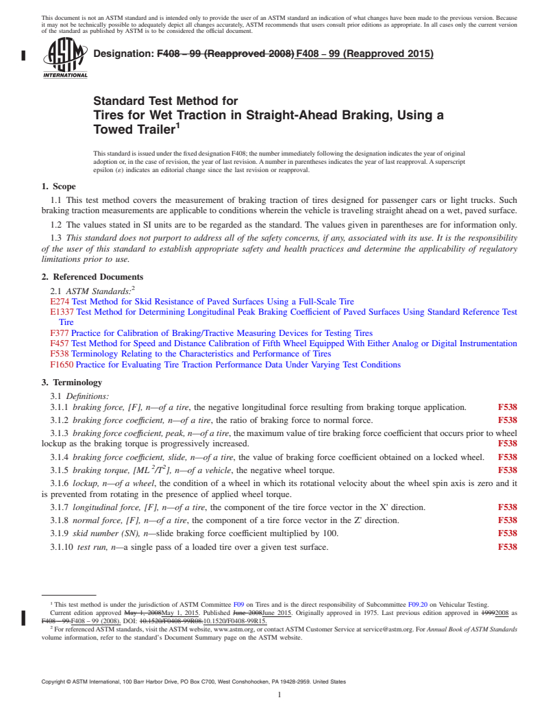
3.1.11 tire axis system, n—the origin of the tire-axis system is the center of the tire contact where the X'-axis is the intersection
of the wheel plane and the road plane with a positive direction forward, the Z'-axis is perpendicular to the road plane with a positive
direction downward, and the Y'-axis is in the road plane, its direction being chosen to make the axis system orthogonal and
right-hand.
3.1.11.1 Discussion—
See Fig. 1. F538
3.1.12 tire forces, [F], n—the external forces acting on a tire by the road. F538
3.1.13 torque, [FL], n—of a wheel, the external torque applied to a tire from a vehicle about the wheel spin axis.
3.1.13.1 Discussion—
Driving torque is positive wheel torque; braking torque is negative wheel torque. F538
3.1.14 vertical load, n—the normal reaction of the tire on the road which is equal to the negative of the normal force. F538
4. Summary of Test Method
4.1 The measurements are conducted on tires mounted on a trailer towed by a vehicle. Brakes are applied firmly until one or
both test tire(s) are locked and then held locked for a period of at least 1.5 s at speeds ranging from 32 km/h (20 mph) to 96 km/h
(60 mph).
4.2 Recommended vehicle test speeds are: 32, 64, and 96 km/h (20, 40, and 60 mph).
5. Significance and Use
5.1 The measured values are traction properties of tires obtained with the towed trailer described here on a given road surface,
under given environmental conditions (ambient and road surface temperature, humidity, wind speed and direction, purity and film
depth of water used to wet the road surface). They are carried out in accordance with the stated test procedures and reflect the
performance of the total tire-vehicle environmental system. A change in any of these factors may change the measurements on a
subsequent run of the test.
5.2 These test methods are suitable for research and development purposes, where tires are compared during a single series of
tests. They may not be suitable for regulatory statutes or specification acceptance, because the values obtained may not necessarily
agree or correlate either in rank order or absolute traction performance level with those obtained on other road surfaces (or the same
surface after additional wear), under other environmental conditions, or other towed trailers, or other test devices, or with results
obtained with other test procedures.
6. Apparatus
6.1 The apparatus consists of tow vehicle and trailer. Vehicle and trailer must comply with all applicable state and federal laws
when operated on public roads.
FIG. 1 Tire-Axis System
F408 − 99 (2015)
6.2 Tow Vehicle:
6.2.1 The tow vehicle shall have the capability of towing the trailer at specified speeds in the range from 32 to 96 km/h (20 to
60 mph), which are to be kept constant to within 0.8 km/h (0.5 mph), even at maximum level of application of braking forces.
6.2.2 The tow vehicle shall be equipped with the following accessories:
6.2.2.1 Equipment to actuate brakes on towed trailer,
6.2.2.2 A water tank to store sufficient water to supply the watering system unless external watering is used,
6.2.2.3 Recording equipment to record signals from transducers installed on the towed trailer,
6.2.2.4 Hitch with adjustable height for towing the trailer, and
6.2.2.5 Optional equipment to monitor and control brakeline pressure, brake application rate, and water application rate.
6.3 Towed Trailer—The trailer shall be equipped with a tow hitch and one or two test wheels which shall be instrumented as
described. A self-watering system is optional (see 6.3.6). Trailers shall be designed to accommodate the range of passenger car and
light truck rim sizes to be tested.
6.3.1 The hitch height shall be no higher than the loaded tire radius, and the distance from hitch ball to axle centerline shall be
no less than ten times the hitch height. For external watering, the trailer hitch on the tow vehicle shall be so arranged that the trailer
tires will run in tracks separate from the tire tracks of the tow vehicle. The minimum track offset of the test tire(s) with respect
to the track of the tow vehicles should be 0.3 m (12 in.).
6.3.2 The trailer shall have provisions for adjustment of vertical load from 65 to 110 % of the appropriate maximum load as
specified in the current yearbook of the appropriate tire and rim standards organization. To meet this requirement for all rim sizes,
two or more trailers designed for different load ranges and equipped with appropriate wheel adaptors may be necessary.
6.3.3 Each of the test wheels shall be equipped with a typical or special automotive hydraulic brake system which can apply
sufficient braking torque to initiate and maintain lockup of the test wheel(s) for the duration of the test.
6.3.4 Each of the test wheels shall have a suspension capable of limiting change of toe and camber to within 60.05° with
maximum vertical suspension displacements. Suspension arms and bushings shall have sufficient rigidity necessary to minimize
free play and compliance under application of maximum braking forces. The suspension system shall provide adequate
load-carrying capacity and be of such a design as to isolate suspension resonance.
6.3.5 The brake application system shall be able to control the time interval between initial brake application and wheel lockup
within a range of 0.2 to 0.5 s with a repeatability of 60.1 s.
6.3.6 The trailer may be optionally equipped with a pavement-wetting system, less the storage tank, which is mounted on the
tow vehicle. The water being applied to the pavement ahead of the test tires shall be supplied by a nozzle suitably designed to
ensure the water layer encountered by the test tire has a uniform cross section at all test speeds with a minimum splash and
over-spray (see Note 1). The nozzle configuration and position shall ensure that the water jets shall be directed toward the test tire
and pointed toward the pavement at an angle of 20 to 30°. The water shall strike the pavement 0.25 to 0.46 m (10 to 18 in.) ahead
of the center of tire contact. The nozzle shall be located 25 mm (1 in.) above the pavement or the minimum height required to clear
obstacles which the tester is expected to encounter, but in no case more than 100 mm (4 in.) above the pavement. The water layer
shall be at least 25 mm (1 in.) wider than the test tire tread and applied so the tire is centrally located between the edges. The
volume of water per unit of wetted width shall be directly proportional to the test speed. The quantity of water applied at 32 km/h
(20 mph) shall be 300 mL/min per mm of width (2.0 gal/min per inch of width) of wetted surface. The rate of water application
at speeds of 64 and 96 km/h (40 and 60 mph) shall be 600 and 900 mL/min per mm of width (4.0 and 6.0 gal/min per inch of
width) of wetted surface, respectively. The nominal values of rate of water application shall be maintained within 610 %. The
water shall be reasonably clean and contain no chemicals such as wetting agents or detergents.
NOTE 1—A suitable nozzle design is described in detail in Test Method E274.
6.4 Instrumentation—Each test wheel position on the trailer shall be equipped with a wheel rotational velocity measuring
system and with transducers to measure the braking force and vertical load at the test wheel.
6.4.1 General Requirements for Measurement System—The instrumentation system shall conform to the following overall
requirements at ambient temperatures between 0 and 43°C (32 and 110°F):
6.4.1.1 Overall system accuracy, force: 61.5 % of vertical load or traction force from 450 N (100 lbf) to full scale,
6.4.1.2 Overall system accuracy, speed: 61.5 % of speed or 60.8 km/h (60.5 mph), whichever is greater,
6.4.1.3 Shunt Calibration—All strain-gage transducers shall be equipped with shunt calibration resistors that can be connected
before or after test sequences. The calibration signal shall be at least 50 % of the full scale for the transducer, and
6.4.1.4 Ruggedness—The exposed portions of the system shall tolerate 100 % relative humidity (rain or spray) and all other
adverse conditions such as dust, shock, and vibrations which may be encountered in regular operation.
6.4.2 Vehicle Speed—To measure vehicle speed, a fifth wheel or non-contact precision speed-measuring system should be used.
Output shall be directly visable to the driver and shall be simultaneously recorded. The fifth wheel or precision speedometer used
to measure vehicle speed shall have specifications in accordance with Test Method F457.
6.4.3 Braking Forces—The braking force-measuring transducers shall measure longitudinal force generated at the tire-road
interface as a result of brake application within a range from 0 to at least 125 % of the applied vertical load. The transducer design
and location shall minimize inertial effects and vibration induced mechanical resonance. The transducer shall have an output
F408 − 99 (2015)
directly proportional to the force with less than 1 % hysteresis and less than 1 % nonlinearity at full scale. It shall have less than
2 % cross-axis sensitivity at full scale. The transducer shall be installed in such a manner as to experience less than 1° angular
rotation with respect to its measuring axes at a maximum expected braking torque.
6.4.4 Vertical Load—The vertical load-measuring transducer shall measure the vertical load at each test wheel during brake
application. The transducer shall have the same specifications as those described in 6.4.3.
6.4.5 Signal Conditioning and Recording System—All signal conditioning and recording equipment shall provide linear output
with necessary gain and data reading resolution to meet the requirements of 6.4.1. Additionally, it shall have the following
specifications:
6.4.5.1 Minimum Frequency Response—d-c flat (61 %) to 30 Hz full scale,
6.4.5.2 Tire vertical load, braking force, vehicle and wheel speeds and a time base must be recorded in phase (0 to 30 Hz 65°),
6.4.5.3 Signal-to-Noise Ratio—at least 20/1,
6.4.5.4 Gain shall be sufficient to permit full-scale display for full-scale input signal level,
6.4.5.5 Input impedance shall be at least ten times larger than the output impedance of the signal source,
6.4.5.6 It must be insensitive to vibrations, acceleration, and changes in ambient temperature. The error in reading shall not
exceed 1 % full scale when subjected to vibrational acceleration of 49.0 m/s (5 g’s) in the 0.5 to 40-Hz frequency range and
operating temperature range from 0°C (32°F) to 43°C (110°F),
6.4.5.7 It shall not be affected by storage temperature variation
...
Questions, Comments and Discussion
Ask us and Technical Secretary will try to provide an answer. You can facilitate discussion about the standard in here.