


ASTM C159-06(2016)
(Specification)Standard Specification for Vitrified Clay Filter Blocks
Standard Specification for Vitrified Clay Filter Blocks
ABSTRACT
This specification establishes the criteria for acceptance, prior to installation, of vitrified clay filter block used in trickling filters for the treatment of sewage and industrial wastes. Filter block shall be formed from fire clay, shale, surface clay, or a combination of these materials. Chemical properties such as acid resistance; and physical properties such as compressive strength, and absorption; are detailed.
SCOPE
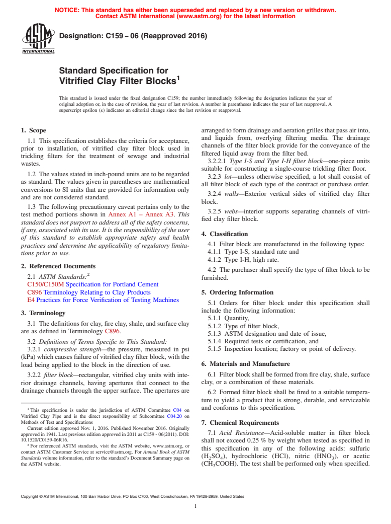
1.1 This specification establishes the criteria for acceptance, prior to installation, of vitrified clay filter block used in trickling filters for the treatment of sewage and industrial wastes.
1.2 The values stated in inch-pound units are to be regarded as standard. The values given in parentheses are mathematical conversions to SI units that are provided for information only and are not considered standard.
1.3 The following precautionary caveat pertains only to the test method portions shown in Annex A1 – Annex A3. This standard does not purport to address all of the safety concerns, if any, associated with its use. It is the responsibility of the user of this standard to establish appropriate safety and health practices and determine the applicability of regulatory limitations prior to use.
General Information
Buy Standard
Standards Content (Sample)
NOTICE: This standard has either been superseded and replaced by a new version or withdrawn.
Contact ASTM International (www.astm.org) for the latest information
Designation:C159 −06 (Reapproved 2016)
Standard Specification for
Vitrified Clay Filter Blocks
This standard is issued under the fixed designation C159; the number immediately following the designation indicates the year of
original adoption or, in the case of revision, the year of last revision. A number in parentheses indicates the year of last reapproval. A
superscript epsilon (´) indicates an editorial change since the last revision or reapproval.
1. Scope arrangedtoformdrainageandaerationgrillesthatpassairinto,
and liquids from, overlying filtering media. The drainage
1.1 This specification establishes the criteria for acceptance,
channels of the filter block provide for the conveyance of the
prior to installation, of vitrified clay filter block used in
filtered liquid away from the filter bed.
trickling filters for the treatment of sewage and industrial
3.2.2.1 Type I-S and Type I-H filter block—one-piece units
wastes.
suitable for constructing a single-course trickling filter floor.
1.2 The values stated in inch-pound units are to be regarded
3.2.3 lot—unless otherwise specified, a lot shall consist of
as standard. The values given in parentheses are mathematical
all filter block of each type of the contract or purchase order.
conversions to SI units that are provided for information only
3.2.4 walls—Exterior vertical sides of vitrified clay filter
and are not considered standard.
block.
1.3 The following precautionary caveat pertains only to the
3.2.5 webs—interior supports separating channels of vitri-
test method portions shown in Annex A1 – Annex A3. This
fied clay filter block.
standard does not purport to address all of the safety concerns,
if any, associated with its use. It is the responsibility of the user
4. Classification
of this standard to establish appropriate safety and health
4.1 Filter block are manufactured in the following types:
practices and determine the applicability of regulatory limita-
4.1.1 Type I-S, standard rate and
tions prior to use.
4.1.2 Type I-H, high rate.
2. Referenced Documents
4.2 The purchaser shall specify the type of filter block to be
2.1 ASTM Standards:
furnished.
C150/C150M Specification for Portland Cement
C896 Terminology Relating to Clay Products
5. Ordering Information
E4 Practices for Force Verification of Testing Machines
5.1 Orders for filter block under this specification shall
include the following information:
3. Terminology
5.1.1 Quantity,
3.1 The definitions for clay, fire clay, shale, and surface clay
5.1.2 Type of filter block,
are as defined in Terminology C896.
5.1.3 ASTM designation and date of issue,
3.2 Definitions of Terms Specific to This Standard: 5.1.4 Required tests or certification, and
5.1.5 Inspection location; factory or point of delivery.
3.2.1 compressive strength—the pressure, measured in psi
(kPa)whichcausesfailureofvitrifiedclayfilterblock,withthe
6. Materials and Manufacture
load being applied to the block in the direction of use.
6.1 Filterblockshallbeformedfromfireclay,shale,surface
3.2.2 filter block—rectangular, vitrified clay units with inte-
clay, or a combination of these materials.
rior drainage channels, having apertures that connect to the
drainage channels through the upper surface. The apertures are
6.2 Formed filter block shall be fired to a suitable tempera-
ture to yield a product that is strong, durable, and serviceable
1 and conforms to this specification.
This specification is under the jurisdiction of ASTM Committee C04 on
Vitrified Clay Pipe and is the direct responsibility of Subcomittee C04.20 on
Methods of Test and Specifications
7. Chemical Requirements
Current edition approved Nov. 1, 2016. Published November 2016. Originally
7.1 Acid Resistance—Acid-soluble matter in filter block
approved in 1941. Last previous edition approved in 2011 as C159 - 06(2011). DOI:
10.1520/C0159-06R16.
shall not exceed 0.25 % by weight when tested as specified in
For referenced ASTM standards, visit the ASTM website, www.astm.org, or
this specification in any of the following acids: sulfuric
contact ASTM Customer Service at service@astm.org. For Annual Book of ASTM
(H SO ), hydrochloric (HCl), nitric (HNO ), or acetic
Standards volume information, refer to the standard’s Document Summary page on 2 4 3
the ASTM website. (CH COOH).The test shall be performed only when specified.
Copyright © ASTM International, 100 Barr Harbor Drive, PO Box C700, West Conshohocken, PA 19428-2959. United States
C159−06 (2016)
7.2 The purchaser shall designate the acid or acids to be shall not extend through the upper surface from the end of the
used in this test. filter block to an aperture opening, nor between aperture
openings.
8. Physical Properties
11. Sampling
8.1 Compressive Strength—Compressive strength tests shall
be performed on full- or half-size block.The average compres-
11.1 Selection of Test Specimens—Full- or half-size filter
sive strength of filter block units shall be at least 450 psi (3.1
block shall be selected by the purchaser or his representative at
mPa), and no individual unit shall have a compressive strength
points he designates when placing the order. Specimens shall
less than 400 psi (2.8 mPa). The compressive strength shall be
meet the dimensions, workmanship, finish, and appearance
calculated on the gross area of the block.
requirements of this specification.
8.2 Absorption—The average absorption of five filter block,
11.2 Number of Specimens—Thenumberofspecimenstobe
determined by 1-h submersion in boiling water, shall not
tested shall be at least five full-size or half-size filter block
exceed 6 % by weight.
selected from each lot, except the acid resistance tests shall be
tested on one specimen from each lot. Additional specimens
9. Dimensions and Permissible Variations
may be tested at the discretion of the purchaser.
9.1 Aperture—The smallest dimension of an aperture in
11.3 Identification—Each specimen shall be marked so that
Type I-S and I-H filter block shall not exceed 1 ⁄2 in. (38 mm),
it may be identified at any time. Filter block specimen
and the total aperture area shall be at least 20 % of the top area.
markings shall not cover more than 5 % of the superficial area
9.2 Drainage Channels:
of the specimen.
9.2.1 The drainage channel cross-sectional area shall be
defined as the channel area lying below the lowest level of the
12. Retesting
aperture. Minimum cross-sectional area of drainage channels
12.1 If test specimens from a lot fail to meet compressive
in filter block shall be as shown in the following table:
strength,absorption,oracidresistancerequirements,themanu-
Drainage Channel Cross-Sectional Area
facturer or seller may sort the shipment into two lots. New
2 2
Type Area, min, in. /ft (cm /m) of width
samples shall be selected by the purchaser from the lot to be
I-S 20 (425)
retained. If the set of test specimens from the retained lot fails
I-H 40 (850)
to meet these requirements, the retained lot shall also be
9.2.2 Drainage channels of filter block shall be curved or
rejected.
narrowed at the bottom to maintain velocity in the channels at
low flow.
13. Test Methods
9.2.3 The minimum depth of drainage channels in filter
block shall be 2 ⁄2 in. (64 mm), measured from the lowest level 13.1 Physical and chemical tests shall be conducted in
accordance with the procedures described in Annex A1 –
of the aperture.
9.2.4 There shall be at least two parallel drainage channels Annex A3.
per foot (0.3 m) of width of Type I-S and I-H filter block.
14. Inspection
9.3 Exterior Walls and Interior Webs—Thicknessofexterior
wallsinTypeI-SandI-Hfilterblockshallbeatleast ⁄16in.(14
14.1 Filter block shall be subject to inspection by the
mm) and interior webs separating drainage channels shall be at
purchaser or the purchaser’s representative. Inspection shall be
least ⁄2 in. (13 mm).
made at the factory or promptly at the point and time of
delivery.Thepurposeofthisinspectionistodeterminewhether
9.4 Permissible Variations in Dimensions:
the filter block meet the dimension, workmanship, appearance,
9.4.1 Exterior dimensions of filter block shall be the dimen-
and marking requirements of this specification.
sions stated by the manufacturer, 6 ⁄4 in./ft (21 mm/m).
9.4.2 The lower bearing surface of filter block shall not vary
14.2 Filter block that do not meet the dimensions,
from a plane by more than ⁄16 in.⁄ft (16 mm/m) of the greatest
workmanship, appearance, and marking specifications shall be
dimension of the block.
rejected and replaced by the manufacturer or seller with filter
blocks that meet the specifications.
10. Workmanship, Finish, and Appearance
14.3 If the purchaser desires compressive strength,
10.1 Filter block shall be substantially free of laminations.
absorption, and acid resistance tests, the purchaser shall select
10.2 Blistersshallnotexceed2in.(51mm)indiameter,and
filter block for testing in accordance with the sampling
blisters or pimples shall not project more than ⁄8 in. (3 mm)
proceduresofthisspecification.Tendaysshallbeallowedafter
above the surface.
sampling for completion of testing.
10.3 Chips shall not exceed 2 in. (51 mm) in length, 1 in.
14.4 The cost of initial inspection and testing shall be borne
(25 mm) in width, and a depth of ⁄16 in. (5 mm).
by the purchaser.The cost of retesting because of failure of the
10.4 Open cracks shall be no longer than 1 ⁄2 in. (38 mm) filter block to pass the initial test shall be borne by the
and surface cracks no longer than 3 in. (76 mm). Open cracks manufacturer.
C159−06 (2016)
15. Certification 16.1.2 Type of filter block.
15.1 When specified in the purchase order or contract, a
17. Precision and Bias
manufacturer’s certification shall be furnished to the purchaser
17.1 No statements are made on the precision or bias of the
stating that the material was manufactured, sampled, tested,
test methods for measuring compressive strength, absorption
and inspected in accordance with this specification and has
percentage, or acid resistance, (see Annexes) since confor-
beenfoundtomeettherequirements.Areportofthetestresults
mance to specific criteria is the only measure for success
shall be furnished when required.
specified in these test methods.
16. Product Marking
18. Keywords
16.1 Identification marks shall be indented legibly on the
exterior of the filter block as follows: 18.1 clay blocks; drains; filters; filter drainage; media;
16.1.1 Manufacturer’s name and media supports; support; trickling filters; underdrains
SUPPLEMENTARY REQUIREMENTS
These requirements apply only to Federal/Military procurement, not domestic sales or transfers.
S1. Government/Military Procurement S2. Packaging and Marking for U.S. Government Procure-
ment:
S1.1 Responsibility for Inspection—Unles
...
This document is not an ASTM standard and is intended only to provide the user of an ASTM standard an indication of what changes have been made to the previous version. Because
it may not be technically possible to adequately depict all changes accurately, ASTM recommends that users consult prior editions as appropriate. In all cases only the current version
of the standard as published by ASTM is to be considered the official document.
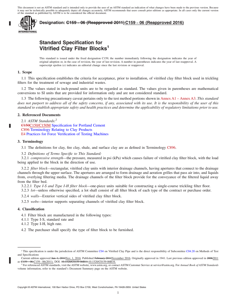
Designation: C159 − 06 (Reapproved 2011) C159 − 06 (Reapproved 2016)
Standard Specification for
Vitrified Clay Filter Blocks
This standard is issued under the fixed designation C159; the number immediately following the designation indicates the year of
original adoption or, in the case of revision, the year of last revision. A number in parentheses indicates the year of last reapproval. A
superscript epsilon (´) indicates an editorial change since the last revision or reapproval.
1. Scope
1.1 This specification establishes the criteria for acceptance, prior to installation, of vitrified clay filter block used in trickling
filters for the treatment of sewage and industrial wastes.
1.2 The values stated in inch-pound units are to be regarded as standard. The values given in parentheses are mathematical
conversions to SI units that are provided for information only and are not considered standard.
1.3 The following precautionary caveat pertains only to the test method portions shown in Annex A1 – Annex A3. This standard
does not purport to address all of the safety concerns, if any, associated with its use. It is the responsibility of the user of this
standard to establish appropriate safety and health practices and determine the applicability of regulatory limitations prior to use.
2. Referenced Documents
2.1 ASTM Standards:
C150C150/C150M Specification for Portland Cement
C896 Terminology Relating to Clay Products
E4 Practices for Force Verification of Testing Machines
3. Terminology
3.1 The definitions for clay, fire clay, shale, and surface clay are as defined in Terminology C896.
3.2 Definitions of Terms Specific to This Standard:
3.2.1 compressive strength—the pressure, measured in psi (kPa) which causes failure of vitrified clay filter block, with the load
being applied to the block in the direction of use.
3.2.2 filter block—rectangular, vitrified clay units with interior drainage channels, having apertures that connect to the drainage
channels through the upper surface. The apertures are arranged to form drainage and aeration grilles that pass air into, and liquids
from, overlying filtering media. The drainage channels of the filter block provide for the conveyance of the filtered liquid away
from the filter bed.
3.2.2.1 Type I-S and Type I-H filter block—one-piece units suitable for constructing a single-course trickling filter floor.
3.2.3 lot—unless otherwise specified, a lot shall consist of all filter block of each type of the contract or purchase order.
3.2.4 walls—Exterior vertical sides of vitrified clay filter block.
3.2.5 webs—interior supports separating channels of vitrified clay filter block.
4. Classification
4.1 Filter block are manufactured in the following types:
4.1.1 Type I-S, standard rate and
4.1.2 Type I-H, high rate.
4.2 The purchaser shall specify the type of filter block to be furnished.
This specification is under the jurisdiction of ASTM Committee C04 on Vitrified Clay Pipe and is the direct responsibility of Subcomittee C04.20 on Methods of Test
and Specifications
Current edition approved Jan. 1, 2011Nov. 1, 2016. Published February 2011November 2016. Originally approved in 1941. Last previous edition approved in 20062011
as C159 – 06.C159 - 06(2011). DOI: 10.1520/C0159-06R11.10.1520/C0159-06R16.
For referenced ASTM standards, visit the ASTM website, www.astm.org, or contact ASTM Customer Service at service@astm.org. For Annual Book of ASTM Standards
volume information, refer to the standard’s Document Summary page on the ASTM website.
Copyright © ASTM International, 100 Barr Harbor Drive, PO Box C700, West Conshohocken, PA 19428-2959. United States
C159 − 06 (2016)
5. Ordering Information
5.1 Orders for filter block under this specification shall include the following information:
5.1.1 Quantity,
5.1.2 Type of filter block,
5.1.3 ASTM designation and date of issue,
5.1.4 Required tests or certification, and
5.1.5 Inspection location; factory or point of delivery.
6. Materials and Manufacture
6.1 Filter block shall be formed from fire clay, shale, surface clay, or a combination of these materials.
6.2 Formed filter block shall be fired to a suitable temperature to yield a product that is strong, durable, and serviceable and
conforms to this specification.
7. Chemical Requirements
7.1 Acid Resistance—Acid-soluble matter in filter block shall not exceed 0.25 % by weight when tested as specified in this
specification in any of the following acids: sulfuric (H SO ), hydrochloric (HCl), nitric (HNO ), or acetic (CH COOH). The test
2 4 3 3
shall be performed only when specified.
7.2 The purchaser shall designate the acid or acids to be used in this test.
8. Physical Properties
8.1 Compressive Strength—Compressive strength tests shall be performed on full- or half-size block. The average compressive
strength of filter block units shall be at least 450 psi (3.1 mPa), and no individual unit shall have a compressive strength less than
400 psi (2.8 mPa). The compressive strength shall be calculated on the gross area of the block.
8.2 Absorption—The average absorption of five filter block, determined by 1-h submersion in boiling water, shall not exceed
6 % by weight.
9. Dimensions and Permissible Variations
9.1 Aperture—The smallest dimension of an aperture in Type I-S and I-H filter block shall not exceed 1 ⁄2 in. (38 mm), and the
total aperture area shall be at least 20 % of the top area.
9.2 Drainage Channels:
9.2.1 The drainage channel cross-sectional area shall be defined as the channel area lying below the lowest level of the aperture.
Minimum cross-sectional area of drainage channels in filter block shall be as shown in the following table:
Drainage Channel Cross-Sectional Area
2 2
Type Area, min, in. /ft (cm /m) of width
I-S 20 (425)
I-H 40 (850)
9.2.2 Drainage channels of filter block shall be curved or narrowed at the bottom to maintain velocity in the channels at low
flow.
9.2.3 The minimum depth of drainage channels in filter block shall be 2 ⁄2 in. (64 mm), measured from the lowest level of the
aperture.
9.2.4 There shall be at least two parallel drainage channels per foot (0.3 m) of width of Type I-S and I-H filter block.
9.3 Exterior Walls and Interior Webs—Thickness of exterior walls in Type I-S and I-H filter block shall be at least ⁄16 in. (14
mm) and interior webs separating drainage channels shall be at least ⁄2 in. (13 mm).
9.4 Permissible Variations in Dimensions:
9.4.1 Exterior dimensions of filter block shall be the dimensions stated by the manufacturer, 6 ⁄4 in./ft (21 mm/m).
9.4.2 The lower bearing surface of filter block shall not vary from a plane by more than ⁄16 in. ⁄ft (16 mm/m) of the greatest
dimension of the block.
10. Workmanship, Finish, and Appearance
10.1 Filter block shall be substantially free of laminations.
10.2 Blisters shall not exceed 2 in. (51 mm) in diameter, and blisters or pimples shall not project more than ⁄8 in. (3 mm) above
the surface.
10.3 Chips shall not exceed 2 in. (51 mm) in length, 1 in. (25 mm) in width, and a depth of ⁄16 in. (5 mm).
10.4 Open cracks shall be no longer than 1 ⁄2 in. (38 mm) and surface cracks no longer than 3 in. (76 mm). Open cracks shall
not extend through the upper surface from the end of the filter block to an aperture opening, nor between aperture openings.
C159 − 06 (2016)
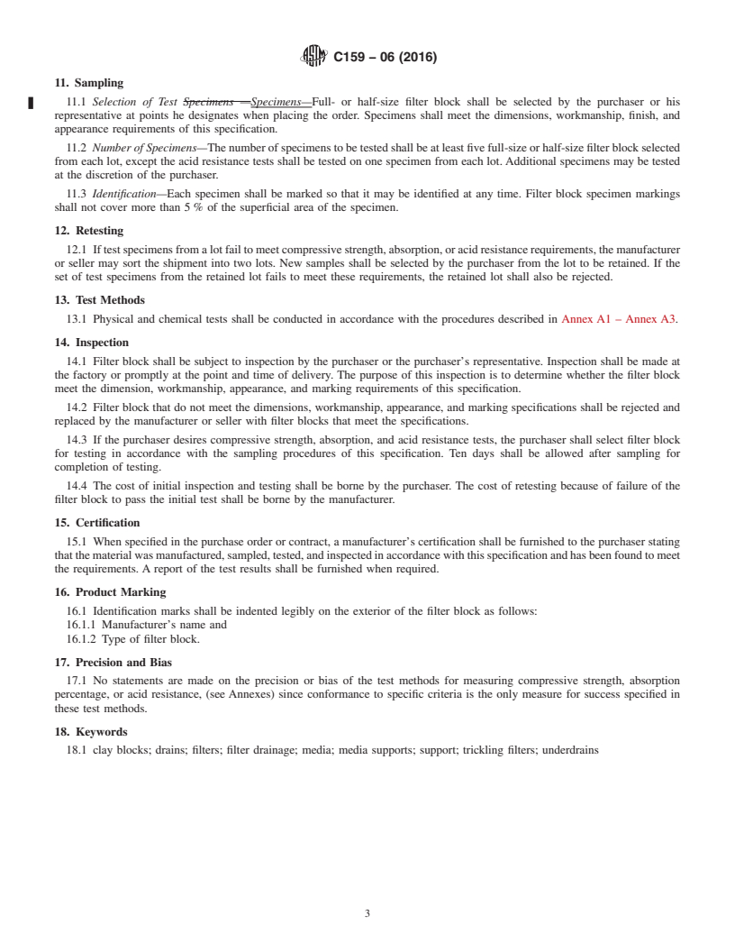
11. Sampling
11.1 Selection of Test Specimens —Specimens—Full- or half-size filter block shall be selected by the purchaser or his
representative at points he designates when placing the order. Specimens shall meet the dimensions, workmanship, finish, and
appearance requirements of this specification.
11.2 Number of Specimens—The number of specimens to be tested shall be at least five full-size or half-size filter block selected
from each lot, except the acid resistance tests shall be tested on one specimen from each lot. Additional specimens may be tested
at the discretion of the purchaser.
11.3 Identification—Each specimen shall be marked so that it may be identified at any time. Filter block specimen markings
shall not cover more than 5 % of the superficial area of the specimen.
12. Retesting
12.1 If test specimens from a lot fail to meet compressive strength, absorption, or acid resistance requirements, the manufacturer
or seller may sort the shipment into two lots. New samples shall be selected by the purchaser from the lot to be retained. If the
set of test specimens from the retained lot fails to meet these requirements, the retained lot shall also be rejected.
13. Test Methods
13.1 Physical and chemical tests shall be conducted in accordance with the procedures described in Annex A1 – Annex A3.
14. Inspection
14.1 Filter block shall be subject to inspection by the purchaser or the purchaser’s representative. Inspection shall be made at
the factory or promptly at the point and time of delivery. The purpose of this inspection is to determine whether the filter block
meet the dimension, workmanship, appearance, and marking requirements of this specification.
14.2 Filter block that do not meet the dimensions, workmanship, appearance, and marking specifications shall be rejected and
replaced by the manufacturer or seller with filter blocks that meet the specifications.
14.3 If the purchaser desires compressive strength, absorption, and acid resistance tests, the purchaser shall select filter block
for testing in accordance with the sampling procedures of this specification. Ten days shall be allowed after sampling for
completion of testing.
14.4 The cost of initial inspection and testing shall be borne by the purchaser. The cost of retesting because of failure of the
filter block to pass the initial test shall be borne by the manufacturer.
15. Certification
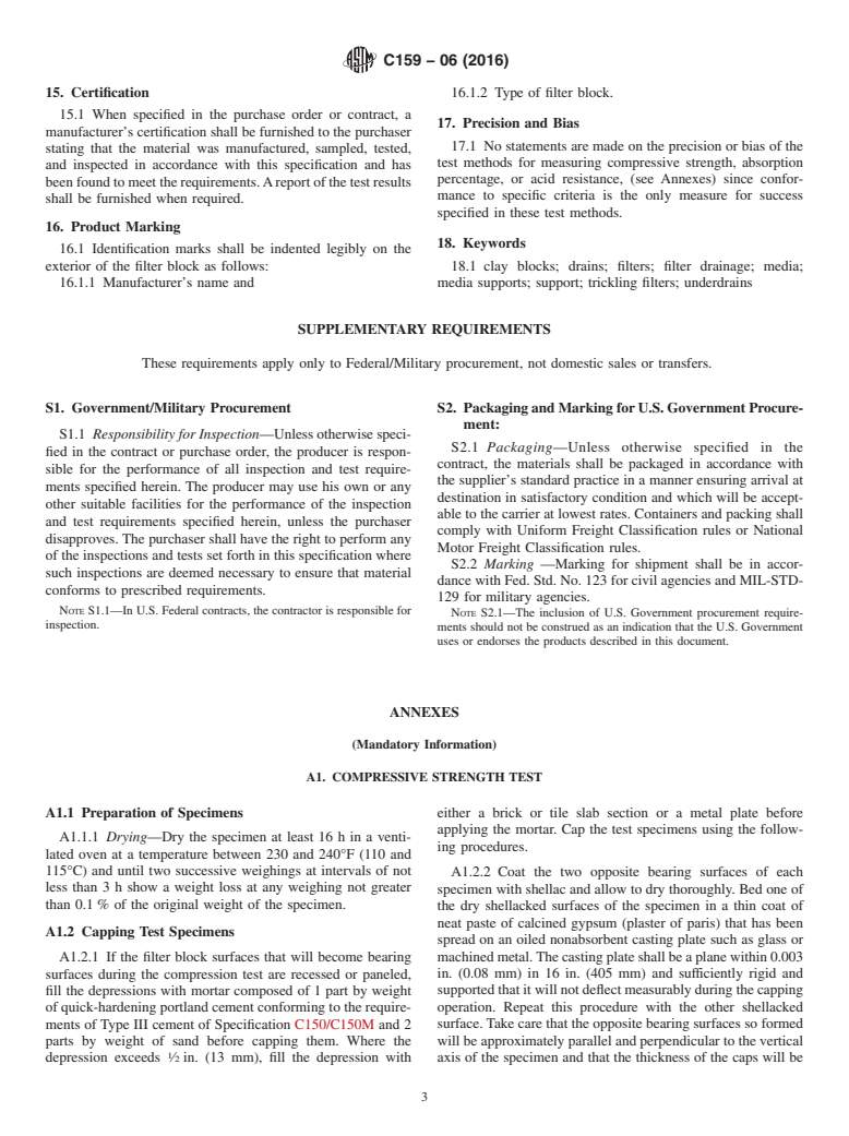
15.1 When specified in the purchase order or contract, a manufacturer’s certification shall be furnished to the purchaser stating
that the material was manufactured, sampled, tested, and inspected in accordance with this specification and has been found to meet
the requirements. A report of the test results shall be furnished when required.
16. Product Marking
16.1 Identification marks shall be indented legibly on the exterior of the filter block as follows:
16.1.1 Manufacturer’s name and
16.1.2 Type of filter block.
17. Precision and Bias
17.1 No statements are made on the precision or bias of the test methods for measuring compressive strength, absorption
percentage, or acid resistance, (see Annexes) since conformance to specific criteria is the only measure for success specified in
these test methods.
18. Keywords
18.1 clay blocks; drains; filters; filter drainage; media; media supports; support; trickling filters; underdrains
C159 − 06 (2016)
SUPPLEMENTARY REQUIREMENTS
These requirements apply only to Federal/Military procurement, not domestic sales or transfers.
S1. Government/Military Procurement
S1.1 Responsibility for Inspection—Unless otherwise specified in the contract or purchase order, the producer is responsible for
the performance of all inspection and test requirements specified herein. The producer may use his own or any other suitable
facilities for the performance of the inspection and test requirements specified herein, unless the purchaser disapproves. The
purchaser shall have the right to perform any of the inspections and tests set forth in this specification where such inspections are
deemed necessary to ensure that material conforms to prescribed requirements.
NOTE S1.1—In U.S. Federal contracts, the contractor is responsible for inspection.
C159 − 06 (2016)
S2. Packaging and Marking for U.S. Government Procurement:
S2.1 Packaging—Unless otherwise specified in the contract, the materials shall be packaged in accordance with the supplier’s
standard practice in a manner ensuring arrival at destination in satisfactory condition and which will be acceptable to the carrier
at lowest rates. Containers and packing shall comply with Uniform Freight Classification rules or National Motor Freight
Classification rules.
S2.2 Marking —Marking for shipment shall be in accordance with Fed. Std. No. 123 for civil agencies and MIL-STD-129 for
military agencies.
NOTE S2.1—The inclusion of U.S. Government procurement requirements should not be construed as an indication that the U.S. Government uses or
endorses the products described in this document.
ANNEXES
(Mandatory Information)
A1. COMPRESSIVE STRENGTH TEST
A1.1 Preparation of Specimens
A1.1.1 Drying—Dry the specimen at least 16 h in a ventilated oven at a temperature between 230 and 240°F (110 and 115°C)
and until two successive weighings at intervals of not less than 3 h show a weight loss at any weighing not greater than 0.1 % of
the original weight of the specimen.
A1.2 Capping Test Specimens
A1.2.1 If the filter block surfaces that will become bearing surfaces during the compression test are recessed or paneled, fill the
depressions with mortar composed of 1 part by weight of quick-hardening portland cement conforming to the requirements of Type
III cement of Specification C150C150/C150M and 2 parts by weight of sand before capping them. Where the depression exceeds
⁄2 in. (13 mm), fill the depression with either a brick or tile slab section or a metal plate before applying the mortar. Cap the test
specimens using the following procedures.
A1.2.2 Coat the two opposite bearing surfaces of each specimen with shellac and allow to dry thoroughly. Bed one of the dry
shellacked surfaces of the specimen in a thin coat of neat paste of calcined gypsum (plaster of paris) that has been spread on an
oiled nonabsorbent casting plate such as glass or machined metal. The casting plate shall be a plane within 0.003 in. (0.08 mm)
in 16 in. (405 mm) and sufficiently rigid and supported that it will not deflect measurably during the capping operation. Repeat
this procedure with the other shellacked surface. Take care that the opposite bearing surfaces so formed will be approximately
parallel and perpendicular to the vertical axis of the specimen and that the thickness of the caps will be approximately the same
and not exceeding ⁄8 in. (3 mm). Age the caps at least 24 h before testing the specimens.
A1.3 Procedure
A1.3.1 Test the filter block specimens in a position such that the load is applied in the same direction as in service. Center the
specimens under the spherical upper bearing within ⁄16 in. (1.6 mm).
A1.3.2 The testing machin
...
Questions, Comments and Discussion
Ask us and Technical Secretary will try to provide an answer. You can facilitate discussion about the standard in here.