


ASTM E1106-12(2017)
(Test Method)Standard Test Method for Primary Calibration of Acoustic Emission Sensors
Standard Test Method for Primary Calibration of Acoustic Emission Sensors
SIGNIFICANCE AND USE
4.1 Transfer Standards—One purpose of this test method is for the direct calibration of displacement transducers for use as secondary standards for the calibration of AE sensors for use in nondestructive evaluation. For this purpose, the transfer standard should be high fidelity and very well behaved and understood. If this can be established, the stated accuracy should apply over the full frequency range up to 1 MHz.
Note 1: The stated accuracy applies only if the transfer standard returns to quiescence, following the transient input, before any wave reflected from the boundary of the calibration block returns to the transfer standard (∼100 μs). For low frequencies with periods on the order of the time window, this condition is problematical to prove.
4.2 Applications Sensors—This test method may also be used for the calibration of AE sensors for use in nondestructive evaluation. Some of these sensors are less well behaved than devices suitable for a transfer standard. The stated accuracy for such devices applies in the range of 100 kHz to 1 MHz and with less accuracy below 100 kHz.
SCOPE
1.1 This test method covers the requirements for the absolute calibration of acoustic emission (AE) sensors. The calibration yields the frequency response of a transducer to waves, at a surface, of the type normally encountered in acoustic emission work. The transducer voltage response is determined at discrete frequency intervals of approximately 10 kHz up to 1 MHz. The input is a given well-established dynamic displacement normal to the mounting surface. The units of the calibration are output voltage per unit mechanical input (displacement, velocity, or acceleration).
1.2 Units—The values stated in SI units are to be regarded as standard. No other units of measurement are included in this standard.
1.3 This standard does not purport to address all of the safety concerns, if any, associated with its use. It is the responsibility of the user of this standard to establish appropriate safety and health practices and determine the applicability of regulatory limitations prior to use.
1.4 This international standard was developed in accordance with internationally recognized principles on standardization established in the Decision on Principles for the Development of International Standards, Guides and Recommendations issued by the World Trade Organization Technical Barriers to Trade (TBT) Committee.
General Information
Buy Standard
Standards Content (Sample)
NOTICE: This standard has either been superseded and replaced by a new version or withdrawn.
Contact ASTM International (www.astm.org) for the latest information
Designation: E1106 − 12 (Reapproved 2017)
Standard Test Method for
Primary Calibration of Acoustic Emission Sensors
This standard is issued under the fixed designation E1106; the number immediately following the designation indicates the year of
original adoption or, in the case of revision, the year of last revision.Anumber in parentheses indicates the year of last reapproval.A
superscript epsilon (´) indicates an editorial change since the last revision or reapproval.
1. Scope E1316Terminology for Nondestructive Examinations
1.1 This test method covers the requirements for the abso-
3. Terminology
lute calibration of acoustic emission (AE) sensors. The cali-
bration yields the frequency response of a transducer to waves, 3.1 Refer to Terminology E1316 for terminology used in
at a surface, of the type normally encountered in acoustic this test method.
emission work. The transducer voltage response is determined
4. Significance and Use
at discrete frequency intervals of approximately 10 kHz up to
1 MHz. The input is a given well-established dynamic dis-
4.1 Transfer Standards—One purpose of this test method is
placement normal to the mounting surface. The units of the
forthedirectcalibrationofdisplacementtransducersforuseas
calibration are output voltage per unit mechanical input
secondarystandardsforthecalibrationofAEsensorsforusein
(displacement, velocity, or acceleration).
nondestructive evaluation. For this purpose, the transfer stan-
1.2 Units—The values stated in SI units are to be regarded dard should be high fidelity and very well behaved and
understood. If this can be established, the stated accuracy
asstandard.Nootherunitsofmeasurementareincludedinthis
standard. should apply over the full frequency range up to 1 MHz.
1.3 This standard does not purport to address all of the
NOTE 1—The stated accuracy applies only if the transfer standard
safety concerns, if any, associated with its use. It is the returns to quiescence, following the transient input, before any wave
reflected from the boundary of the calibration block returns to the transfer
responsibility of the user of this standard to establish appro-
standard (;100 µs). For low frequencies with periods on the order of the
priate safety and health practices and determine the applica-
time window, this condition is problematical to prove.
bility of regulatory limitations prior to use.
4.2 Applications Sensors—This test method may also be
1.4 This international standard was developed in accor-
usedforthecalibrationofAEsensorsforuseinnondestructive
dance with internationally recognized principles on standard-
evaluation. Some of these sensors are less well behaved than
ization established in the Decision on Principles for the
devicessuitableforatransferstandard.Thestatedaccuracyfor
Development of International Standards, Guides and Recom-
such devices applies in the range of 100 kHz to 1 MHz and
mendations issued by the World Trade Organization Technical
with less accuracy below 100 kHz.
Barriers to Trade (TBT) Committee.
2. Referenced Documents 5. General Requirements
2.1 ASTM Standards: 5.1 Aprimary difficulty in any calibration of a mechanical/
E114 Practice for Ultrasonic Pulse-Echo Straight-Beam electrical transduction device is the determination of the
Contact Testing mechanical-motion input to the device. To address this
E494Practice for Measuring Ultrasonic Velocity in Materi- difficulty, this calibration procedure uses (i) a standard trans-
als ducer whose absolute sensitivity is known from its design and
physical characteristics; and also (ii) a source that produces
E650Guide for Mounting Piezoelectric Acoustic Emission
Sensors motion that approximates a waveform calculable from theory.
The use of two independent sources of information confers a
degree of redundancy that is employed to confirm the validity
This test method is under the jurisdiction of ASTM Committee E07 on
of the measurements and quantify the experimental errors.
Nondestructive Testing and is the direct responsibility of Subcommittee E07.04 on
Acoustic Emission Method.
Briefly stated, the sensitivity of the transfer standard (or other
CurrenteditionapprovedJune1,2017.PublishedJuly2017.Originallyapproved
sensor under test) is determined by comparison with the
in 1986. Last previous edition approved in 2012 as E1106-12. DOI: 10.1520/
standard transducer, while knowledge of a part of the theoreti-
E1106-12R17.
For referenced ASTM standards, visit the ASTM website, www.astm.org, or cal waveform is used as a check.
contact ASTM Customer Service at service@astm.org. For Annual Book of ASTM
5.2 Test Block and Mechanical Input—The mechanical
Standards volume information, refer to the standard’s Document Summary page on
the ASTM website. input to the sensors is obtained by pressing a glass capillary
Copyright © ASTM International, 100 Barr Harbor Drive, PO Box C700, West Conshohocken, PA 19428-2959. United States
E1106 − 12 (2017)
down onto the surface of a large test block until it breaks. The isticsamenabletotheoreticalcalculation.Itshouldalsopresent
reasons for selecting this approach are: (a) capillary breaks are no appreciable dynamic loading to the surface it is measuring.
localized and short in duration, like natural acoustic emission
5.3.1 For a calibration, the standard transducer and the
events; and (b) use of a large block simplifies wave propaga-
device to be calibrated are both placed on the same surface of
tion and makes sensor output less dependent on arbitrary
the block as the mechanical input and equidistant in opposite
features of block geometry.
directions from it. This guarantees that both experience the
5.2.1 Prior to the fracture of the glass capillary, the force it
same displacement-time history. Comparison of the output of
exerts on the surface is distributed over an area on the order of
the transfer standard or AE sensor with the output of the
2 mm × 0.3 mm. When the glass capillary breaks, the force it
standard transducer yields a calibration of the device under
was applying to the surface is abruptly relieved, within a time
test.
ontheorderof0.2to0.3µs.Withinthelimitationsarisingfrom
5.3.2 Otherrelativegeometriesfortheinputandtransducers
these finite dimensions, the breaking of the capillary approxi-
are possible, but results from other geometries should only be
mates a step force function at a point on the surface of the
used to supplement results from the “same surface” geometry.
block. Theoretical solutions for the idealized response of a
AE waves in structures are most frequently dominated by
half-spacetoanormalpoint-forcestepfunctionintimeapplied
4,5 surface wave phenomena, and the calibration should be based
to the surface are available. The outputs of flat-response
on the transducer’s response to such waves.
transducershavebeenfoundtobeagoodmatch(exceptforthe
infinite amplitude part) to the theoretical waveforms, support-
5.4 Units for the Calibration—An AE sensor may be con-
ing the use of this theory as a check on the primary calibration
sideredtorespondtoeitherstressorstrainatitsfrontface.The
of sensors. An example with a flat response transducer is
actual stress and strain at the front face of a mounted sensor
shown in Figure 9. The vertical component of the theoretical
depend on the interaction between the mechanical impedance
waveform comprises three parts: (a) a low-amplitude response
of the sensor (load) and that of the mounting block (driver).
beginning at time d/c , where d is the distance from the source
L
Neither the stress nor the strain is amenable to direct measure-
and c is the longitudinal wave velocity; (b) a short impulsive
L
ment at this location. However, the free displacement that
response between times d/c and d/c , where c is the shear
S R S
would occur at the surface of the block in the absence of the
wave velocity and c the Rayleigh wave velocity; (c) a step
R
sensor can be inferred from measurements made elsewhere on
function beginning at d/c . It is the last of these that is salient
R
the surface. Also, the ideal displacement (except at the point
for checking the sensor calibration. The theoretical height
wherethedisplacementbecomesinfinite)foranidealsourceis
(shelf value [see Figure 9 for determination of the shelf value],
known from theory. Since AE sensors are used to monitor
relative to zero displacement) of this displacement step u is:
motion at a free surface of a structure and interactive effects
u 5 F A/4πµd~A 2 1!
3 0 between sensor and structure are generally of no interest, the
free surface motion is the appropriate input variable. It is,
where F is the applied force (which is measured), µ is the
therefore, recommended that the units of calibration should be
shearmodulus(calculatedbyuseoftheshearwavevelocity)of
voltage per unit of free motion; for example, volts per metre.
thetestblock, A=(c /c ) and disthedistancefromthesource
L S
to the transducer.
5.5 Block Material:
5.3 Absolute Displacement Measurement—An absolute 5.5.1 Since the calibration depends on the interaction of the
measurement of the dynamic normal surface displacement of
mechanical impedance of the block and that of theAE sensor,
the block is required for this calibration test method. The a calibration procedure must specify the material of the block.
transducer used for this measurement is a standard transducer
Calibrations performed on blocks of different materials will
against which the device under test is compared. The standard
yield transducer sensitivity versus frequency curves that are
transducer should meet or exceed the performance of the
different in shape and in average magnitude. The amount by
capacitive transducer described by Breckenridge and Greens-
which such averages differ may be very large. A transducer
pan. The important characteristics of the standard transducer
calibrated on a glass or aluminum block will have an average
include high fidelity, high sensitivity, and operating character-
sensitivity that may be from 50 to 100% of the value obtained
on steel, and will have an average sensitivity that may be as
little as 3% of the value obtained on steel if calibrated on a
3 polymethyl methacrylate block. In general, the sensitivity will
Burks,Brian,“Re-ExaminationofNISTAcousticEmissionSensorCalibration:
Part I – Modeling the Loading from Glass Capillary Fracture,” Journal of Acoustic
be less if the block is made of a less rigid or less dense
Emission, Vol. 29, pp. 167–174.
material.
Breckenridge, F. R., “Acoustic Emission Transducer Calibration by Means of
5.5.2 TheRayleighspeedinthematerialoftheblockaffects
the Seismic Surface Pulse,” Journal of Acoustic Emission Vol 1, pp. 87–94.
Hsu, N. N., and Breckenridge, F. R., “Characterization and Calibration of
surface wave calibrations. For a sensor having a circular
Acoustic Emission Sensors,” Materials Evaluation, Vol 39, 1981, pp. 60–68.
aperture (mounting face) with uniform sensitivity over the
PaulG.Richards,“ElementarySolutionstoLamb’sProblemforaPointSource
face, the aperture effect predicts nulls at the zeroes of J (ka),
and their Relevance to Three- Dimensional Studies of Spontaneous Crack
Propagation,” Bull. of the Seismological Society of America,Vol69,No.4,1979,pp.
where k=2πf⁄c , and f =frequency, c =Rayleigh speed, and
R R
947–956.
a =radius of the sensor face (active element). Hence, the
Breckenridge, F. R., and Greenspan, M., “Surface-Wave Displacement: Abso-
frequencies at which the nulls occur are dependent upon the
lute Measurements Using a Capacitive Transducer,” Journal, Acoustic Society of
America, Vol 69, pp 1177–1185. Rayleigh speed.
E1106 − 12 (2017)
6. Apparatus 6.1.3 As a check, the shelf value (see section 5.2.1) deter-
mined from the standard transducer output is compared with
6.1 A typical basic scheme for the calibration is shown in
the value determined from the measured capillary break force
Fig. 1. A glass capillary, B, of diameter about 0.2 mm, is
using the equation in 5.2.1. This comparison should provide
squeezedbetweenthetipoftheloadingscrew, C,andtheupper
supporting evidence that the precision stated in 8.5 has been
face of the large steel transfer block, A. When the capillary
attained. This check should be made at least one time for each
breaks, the sudden release of force is nearly a step function
calibration performed.
whose risetime is of the order of 0.2 µs to 0.3 µs. The
magnitude of the force step is measured by the combination of
6.2 The Transfer Block—The transfer block must be made
thePZTdisc, D,intheloadingscrewandachargeamplifier, E,
from specially chosen material. It should be as defect-free as
connected to a waveform recorder, F. Alternatively, the force
possible and should undergo an ultrasonic longitudinal exami-
step can be measured by a strain-gage load cell within the
nation at 2.25 MHz. The method described in Practice E114
loading screw with standard electronic conditioning for the
should be used. The block should contain no flaws which give
strain gages. The standard capacitive transducer, G, and the
a reflection larger than 10% of the first back wall reflection.
device under test, H, are placed equally distant (usually 100
The material should also be highly uniform as determined by
mm) from the source and in opposite directions from it. It is
pulse-echo time of flight measurements through the block at a
obvious from the symmetry that the surface displacements
minimumof15locationsregularlyspacedoverthesurface(see
wouldbethesameatthetwotransducerlocationsifitwerenot
Practice E494). The individual values of the longitudinal and
for the loading effects of the transducers. The loading effect of
shear wave speed should differ from the average by no more
the standard capacitive transducer is negligible and the loading 4
than 61partand 63partsin10 ,respectively.Atransferblock
effect of the unknown sensor is part of its calibration.
and calibration apparatus is shown in Fig. 2.
6.1.1 Voltage transients from the two transducers are re-
corded simultaneously by digital recorders, I, and the informa- 6.3 The Source—The source events, which are a useful
approximation to force step functions, are to be made by
tion is stored for processing by the computer, J.
6.1.2 With such a system, it is possible to do the necessary breaking glass capillary tubing (Fig. 3). The capillaries are
comparison between the signal from the unknown sensor and drawn down from ordinary laboratory glass tubing made of
that from the standard transducer. borosilicate glass. Sizes of the capillary may range from about
A—steel transfer block
B—capillary source
C—loading screw
D—PZT disc or strain-gage load cell
E—charge amplifier or strain gage conditioning electronics
F—transient
...
This document is not an ASTM standard and is intended only to provide the user of an ASTM standard an indication of what changes have been made to the previous version. Because
it may not be technically possible to adequately depict all changes accurately, ASTM recommends that users consult prior editions as appropriate. In all cases only the current version
of the standard as published by ASTM is to be considered the official document.
Designation: E1106 − 12 E1106 − 12 (Reapproved 2017)
Standard Test Method for
Primary Calibration of Acoustic Emission Sensors
This standard is issued under the fixed designation E1106; the number immediately following the designation indicates the year of
original adoption or, in the case of revision, the year of last revision. A number in parentheses indicates the year of last reapproval. A
superscript epsilon (´) indicates an editorial change since the last revision or reapproval.
1. Scope*Scope
1.1 This test method covers the requirements for the absolute calibration of acoustic emission (AE) sensors. The calibration
yields the frequency response of a transducer to waves, at a surface, of the type normally encountered in acoustic emission work.
The transducer voltage response is determined at discrete frequency intervals of approximately 10 kHz up to 1 MHz. The input
is a given well-established dynamic displacement normal to the mounting surface. The units of the calibration are output voltage
per unit mechanical input (displacement, velocity, or acceleration).
1.2 Units—The values stated in SI units are to be regarded as standard. No other units of measurement are included in this
standard.
1.3 This standard does not purport to address all of the safety concerns, if any, associated with its use. It is the responsibility
of the user of this standard to establish appropriate safety and health practices and determine the applicability of regulatory
limitations prior to use.
1.4 This international standard was developed in accordance with internationally recognized principles on standardization
established in the Decision on Principles for the Development of International Standards, Guides and Recommendations issued
by the World Trade Organization Technical Barriers to Trade (TBT) Committee.
2. Referenced Documents
2.1 ASTM Standards:
E114 Practice for Ultrasonic Pulse-Echo Straight-Beam Contact Testing
E494 Practice for Measuring Ultrasonic Velocity in Materials
E650 Guide for Mounting Piezoelectric Acoustic Emission Sensors
E1316 Terminology for Nondestructive Examinations
3. Terminology
3.1 Refer to Terminology E1316 for terminology used in this test method.
4. Significance and Use
4.1 Transfer Standards—One purpose of this test method is for the direct calibration of displacement transducers for use as
secondary standards for the calibration of AE sensors for use in nondestructive evaluation. For this purpose, the transfer standard
should be high fidelity and very well behaved and understood. If this can be established, the stated accuracy should apply over
the full frequency range up to 1 MHz.
NOTE 1—The stated accuracy applies only if the transfer standard returns to quiescence, following the transient input, before any wave reflected from
the boundary of the calibration block returns to the transfer standard (;100 μs). For low frequencies with periods on the order of the time window, this
condition is problematical to prove.
4.2 Applications Sensors—This test method may also be used for the calibration of AE sensors for use in nondestructive
evaluation. Some of these sensors are less well behaved than devices suitable for a transfer standard. The stated accuracy for such
devices applies in the range of 100 kHz to 1 MHz and with less accuracy below 100 kHz.
This test method is under the jurisdiction of ASTM Committee E07 on Nondestructive Testing and is the direct responsibility of Subcommittee E07.04 on Acoustic
Emission Method.
Current edition approved June 15, 2012June 1, 2017. Published September 2012July 2017. Originally approved in 1986. Last previous edition approved in 20072012 as
E1106 - 07.E1106 - 12. DOI: 10.1520/E1106-12.10.1520/E1106-12R17.
For referenced ASTM standards, visit the ASTM website, www.astm.org, or contact ASTM Customer Service at service@astm.org. For Annual Book of ASTM Standards
volume information, refer to the standard’s Document Summary page on the ASTM website.
*A Summary of Changes section appears at the end of this standard
Copyright © ASTM International, 100 Barr Harbor Drive, PO Box C700, West Conshohocken, PA 19428-2959. United States
E1106 − 12 (2017)
5. General Requirements
5.1 A primary difficulty in any calibration of a mechanical/electrical transduction device is the determination of the
mechanical-motion input to the device. To address this difficulty, this calibration procedure uses (i) a standard transducer whose
absolute sensitivity is known from its design and physical characteristics; and also (ii) a source that produces motion that
approximates a waveform calculable from theory. The use of two independent sources of information confers a degree of
redundancy that is employed to confirm the validity of the measurements and quantify the experimental errors. Briefly stated, the
sensitivity of the transfer standard (or other sensor under test) is determined by comparison with the standard transducer, while
knowledge of a part of the theoretical waveform is used as a check.
5.2 Test Block and Mechanical Input—The mechanical input to the sensors is obtained by pressing a glass capillary down onto
the surface of a large test block until it breaks. The reasons for selecting this approach are: (a) capillary breaks are localized and
short in duration, like natural acoustic emission events; and (b) use of a large block simplifies wave propagation and makes sensor
output less dependent on arbitrary features of block geometry.
5.2.1 Prior to the fracture of the glass capillary, the force it exerts on the surface is distributed over an area on the order of 2
mm × 0.3 mm. When the glass capillary breaks, the force it was applying to the surface is abruptly relieved, within a time on the
order of 0.2 to 0.3 μs. Within the limitations arising from these finite dimensions, the breaking of the capillary approximates a step
force function at a point on the surface of the block. Theoretical solutions for the idealized response of a half-space to a normal
4,5
point-force step function in time applied to the surface are available. The outputs of flat-response transducers have been found
to be a good match (except for the infinite amplitude part) to the theoretical waveforms, supporting the use of this theory as a check
on the primary calibration of sensors. An example with a flat response transducer is shown in Figure 9. The vertical component
of the theoretical waveform comprises three parts: (a) a low-amplitude response beginning at time d/c , where d is the distance
L
from the source and c is the longitudinal wave velocity; (b) a short impulsive response between times d/c and d/c , where c is
L S R S
the shear wave velocity and c the Rayleigh wave velocity; (c) a step function beginning at d/c . It is the last of these that is salient
R R
for checking the sensor calibration. The theoretical height (shelf value [see Figure 9 for determination of the shelf value], relative
to zero displacement) of this displacement step u is:
u 5 F A/4πμd~A 2 1!
3 0
where F is the applied force (which is measured), μ is the shear modulus (calculated by use of the shear wave velocity) of the
test block, A = (c /c ) and d is the distance from the source to the transducer.
L S
5.3 Absolute Displacement Measurement—An absolute measurement of the dynamic normal surface displacement of the block
is required for this calibration test method. The transducer used for this measurement is a standard transducer against which the
device under test is compared. The standard transducer should meet or exceed the performance of the capacitive transducer
described by Breckenridge and Greenspan. The important characteristics of the standard transducer include high fidelity, high
sensitivity, and operating characteristics amenable to theoretical calculation. It should also present no appreciable dynamic loading
to the surface it is measuring.
5.3.1 For a calibration, the standard transducer and the device to be calibrated are both placed on the same surface of the block
as the mechanical input and equidistant in opposite directions from it. This guarantees that both experience the same
displacement-time history. Comparison of the output of the transfer standard or AE sensor with the output of the standard
transducer yields a calibration of the device under test.
5.3.2 Other relative geometries for the input and transducers are possible, but results from other geometries should only be used
to supplement results from the “same surface” geometry. AE waves in structures are most frequently dominated by surface wave
phenomena, and the calibration should be based on the transducer’s response to such waves.
5.4 Units for the Calibration—An AE sensor may be considered to respond to either stress or strain at its front face. The actual
stress and strain at the front face of a mounted sensor depend on the interaction between the mechanical impedance of the sensor
(load) and that of the mounting block (driver). Neither the stress nor the strain is amenable to direct measurement at this location.
However, the free displacement that would occur at the surface of the block in the absence of the sensor can be inferred from
measurements made elsewhere on the surface. Also, the ideal displacement (except at the point where the displacement becomes
infinite) for an ideal source is known from theory. Since AE sensors are used to monitor motion at a free surface of a structure
and interactive effects between sensor and structure are generally of no interest, the free surface motion is the appropriate input
variable. It is, therefore, recommended that the units of calibration should be voltage per unit of free motion; for example, volts
per metre.
Burks, Brian, “Re-Examination of NIST Acoustic Emission Sensor Calibration: Part I – Modeling the Loading from Glass Capillary Fracture,” Journal of Acoustic
Emission, Vol. 29, pp. 167–174.
Breckenridge, F. R., “Acoustic Emission Transducer Calibration by Means of the Seismic Surface Pulse,” Journal of Acoustic Emission Vol 1, pp. 87–94.
Hsu, N. N., and Breckenridge, F. R., “Characterization and Calibration of Acoustic Emission Sensors,” Materials Evaluation, Vol 39, 1981, pp. 60–68.
Paul G. Richards, “Elementary Solutions to Lamb’s Problem for a Point Source and their Relevance to Three- Dimensional Studies of Spontaneous Crack Propagation,”
Bull. of the Seismological Society of America, Vol 69, No. 4, 1979, pp. 947–956.
Breckenridge, F. R., and Greenspan, M., “Surface-Wave Displacement: Absolute Measurements Using a Capacitive Transducer,” Journal, Acoustic Society of America,
Vol 69, pp 1177–1185.
E1106 − 12 (2017)
5.5 Block Material:
5.5.1 Since the calibration depends on the interaction of the mechanical impedance of the block and that of the AE sensor, a
calibration procedure must specify the material of the block. Calibrations performed on blocks of different materials will yield
transducer sensitivity versus frequency curves that are different in shape and in average magnitude. The amount by which such
averages differ may be very large. A transducer calibrated on a glass or aluminum block will have an average sensitivity that may
be from 50 to 100 % of the value obtained on steel, and will have an average sensitivity that may be as little as 3 % of the value
obtained on steel if calibrated on a polymethyl methacrylate block. In general, the sensitivity will be less if the block is made of
a less rigid or less dense material.
5.5.2 The Rayleigh speed in the material of the block affects surface wave calibrations. For a sensor having a circular aperture
(mounting face) with uniform sensitivity over the face, the aperture effect predicts nulls at the zeroes of J (ka), where k = 2πf ⁄c ,
1 R
and f = frequency, c = Rayleigh speed, and a = radius of the sensor face (active element). Hence, the frequencies at which the
R
nulls occur are dependent upon the Rayleigh speed.
6. Apparatus
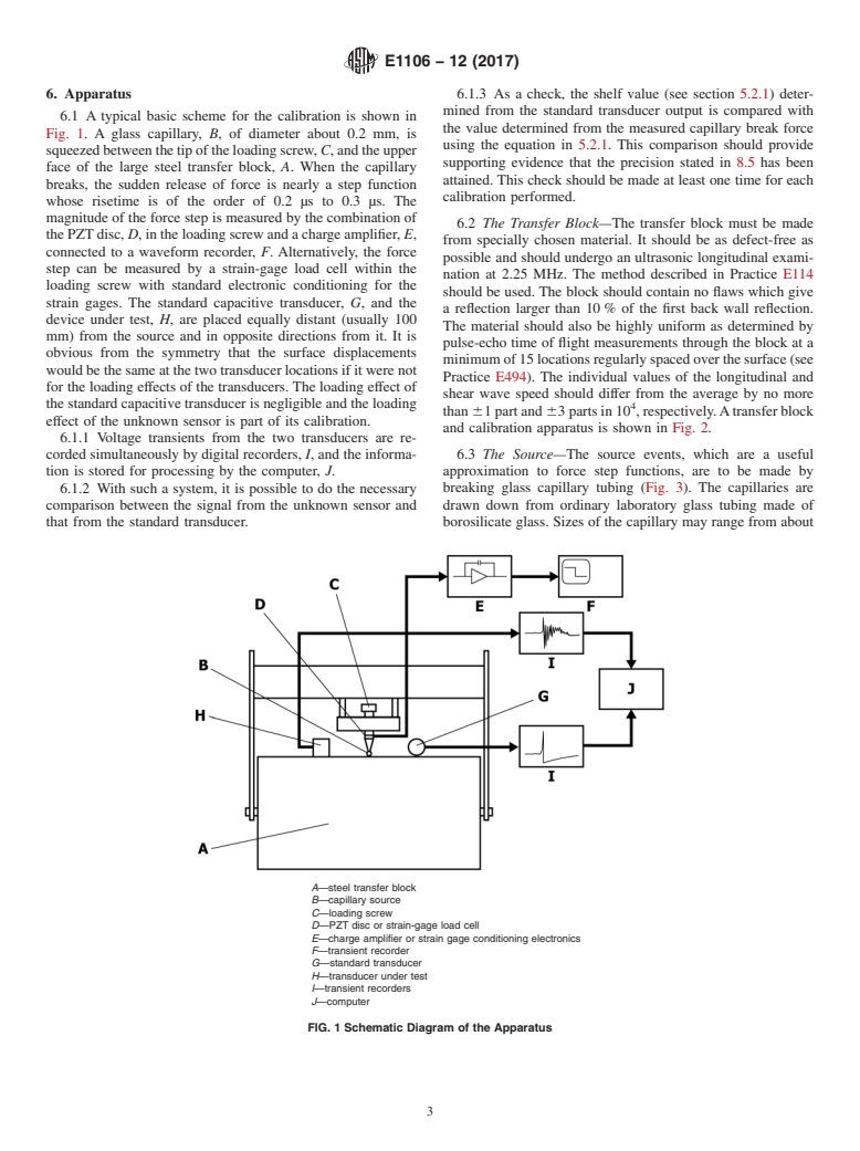
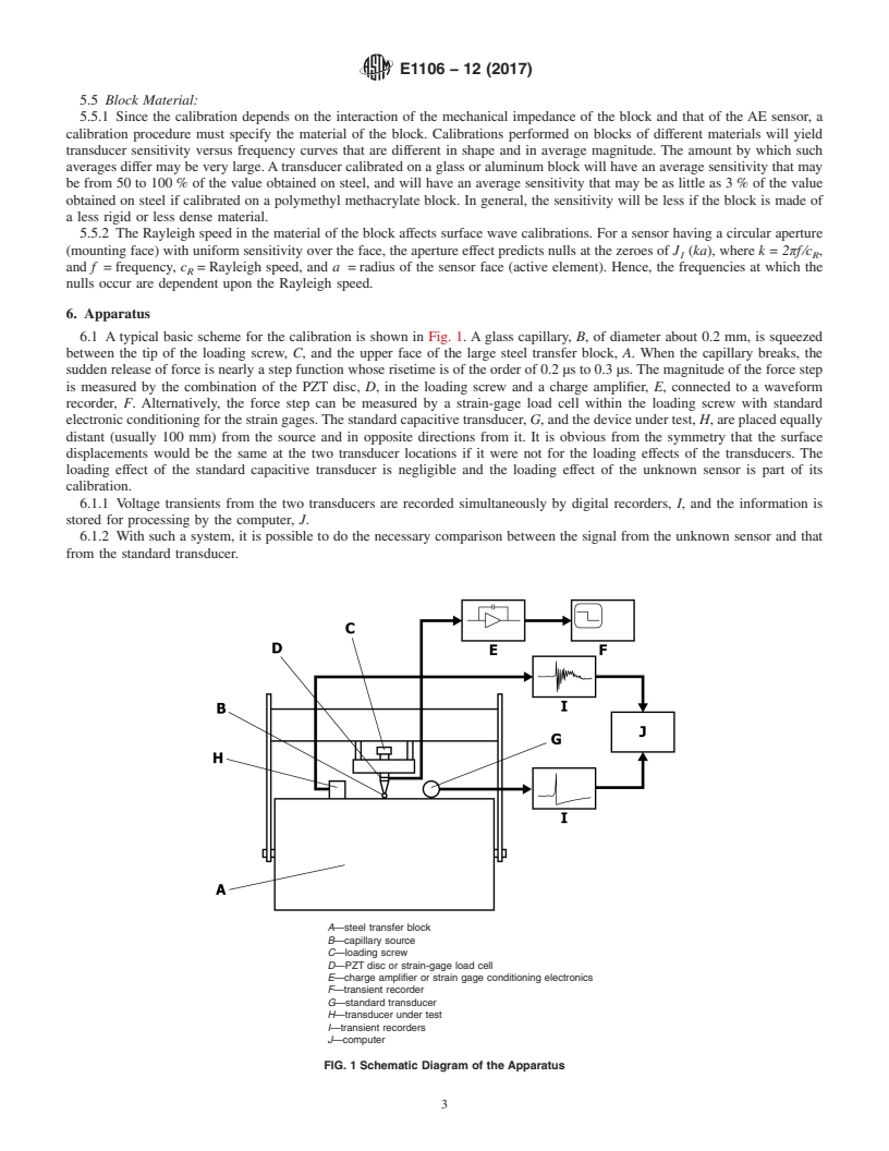
6.1 A typical basic scheme for the calibration is shown in Fig. 1. A glass capillary, B, of diameter about 0.2 mm, is squeezed
between the tip of the loading screw, C, and the upper face of the large steel transfer block, A. When the capillary breaks, the
sudden release of force is nearly a step function whose risetime is of the order of 0.2 μs to 0.3 μs. The magnitude of the force step
is measured by the combination of the PZT disc, D, in the loading screw and a charge amplifier, E, connected to a waveform
recorder, F. Alternatively, the force step can be measured by a strain-gage load cell within the loading screw with standard
electronic conditioning for the strain gages. The standard capacitive transducer, G, and the device under test, H, are placed equally
distant (usually 100 mm) from the source and in opposite directions from it. It is obvious from the symmetry that the surface
displacements would be the same at the two transducer locations if it were not for the loading effects of the transducers. The
loading effect of the standard capacitive transducer is negligible and the loading effect of the unknown sensor is part of its
calibration.
6.1.1 Voltage transients from the two transducers are recorded simultaneously by digital recorders, I, and the information is
stored for processing by the computer, J.
6.1.2 With such a system, it is possible to do the necessary comparison between the signal from the unknown sensor and that
from the standard transducer.
A—steel transfer block
B—capillary source
C—loading screw
D—PZT disc or strain-gage load cell
E—charge amplifier or strain gage conditioning electronics
F—transient recorder
G—standard transducer
H—transducer under test
I—transient recorders
J—computer
FIG. 1 Schematic Diagram of the Apparatus
E1106 − 12 (2017)
6.1.3 As a check, the shelf value (see section 5.2.1) determined from the standard transducer output is compared with the value
determined from the measured capillary break force using the equation in 5.2.1. This comparison should provide supporting
evidence that the precision stated in 8.5 has been attained. This check should be made at least one time for each calibration
performed.
6.2 The Transfer Block—The transfer block must be made from specially chosen material. It should be as defect-free as possible
and should undergo an ultrasonic longitudinal examination at 2.25 MHz. The method described in Practice E114 shoul
...
Questions, Comments and Discussion
Ask us and Technical Secretary will try to provide an answer. You can facilitate discussion about the standard in here.