


ASTM B826-09(2015)
(Test Method)Standard Test Method for Monitoring Atmospheric Corrosion Tests by Electrical Resistance Probes
Standard Test Method for Monitoring Atmospheric Corrosion Tests by Electrical Resistance Probes
SIGNIFICANCE AND USE
4.1 Corrosivity monitoring of test environments provides a means to monitor an integrated value of test corrosivity which cannot be evaluated from test parameters themselves, such as temperature, humidity, and gas concentration. As such the monitor value can be used for specification purposes such as test validation. Electrical resistance monitoring of conductors exposed to corrosive media is a well-established practice.3,4,5,6
4.2 The resistance method assumes uniform corrosion over the entire surface of the exposed metal conductor segment. Local corrosion such as pitting, crevice, or grain boundary corrosion may provide invalid estimates of test corrosivity. Marked changes in slope of the curve of electrical resistance ratio versus time may indicate undesired processes which can be due to deficiencies in the test atmosphere or in the monitor itself.
4.3 Because of limitations of the diffusion process within the corrosion product formed on the metal conductor segment of the RM probe when passivating corrosion films are formed, resistance monitoring may not be useful for test chamber monitoring purposes for very long test exposures. Chamber monitoring is dependent on detecting changes in the rate of corrosion of the RM as an indicator signal that specified gas concentrations must be reverified. However, low corrosion rates limit the absolute value of the rate of change of corrosion rate with change of test conditions; for parabolic film growth processes, the growth rate decreases with time limiting the sensitivity of the RM at extended test times.
4.4 Since corrosion rate can be a complex function of test parameters in MFG tests with any given metal primarily responsive to a subset of the gases in the MFG environment, more than one type metal resistance probe is required in order to assist in maintenance of relative gas concentrations. For such test specifications, values of resistance ratios must be referred to ratios obtained under known test conditions a...
SCOPE
1.1 This test method provides a means for monitoring corrosivity of environmental tests that involve exposure to corrosive gases.
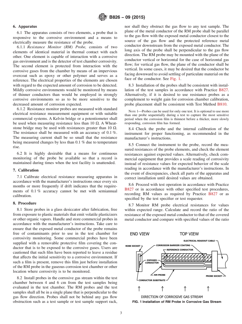
1.2 This test method uses a resistance monitor (RM) probe fabricated from a chosen metal conductor, with one conductor segment uncovered to permit exposure of the chosen metal conductor to the corrosive gas mixture and the second conductor segment covered to protect the metal conductor of this segment from direct attack by the corrosive gas mixture. The covered conductor segment provides a reference for evaluating changes in the uncovered segment. The ratio of the resistance of the exposed segment to that of the covered segment provides a measure of the amount of metal conductor that has reacted with the corrosive gas test environment to form poorly conducting corrosion product, thus providing a measure of test corrosivity.
1.3 Resistance monitoring is applicable to a broad range of test conditions by selection of the appropriate metal conductor and initial metal thickness.
1.4 This method is similar in intent to Test Methods B808.
1.5 The values stated in SI units are to be regarded as standard. No other units of measurement are included in this standard.
1.6 This standard does not purport to address all of the safety concerns, if any, associated with its use. It is the responsibility of the user of this standard to become familiar with all hazards including those identified in the appropriate Material Safety Data Sheet (MSDS) for this product/material as provided by the manufacturer, to establish appropriate safety and health practices, and determine the applicability of regulatory limitations prior to use.
General Information
Buy Standard
Standards Content (Sample)
NOTICE: This standard has either been superseded and replaced by a new version or withdrawn.
Contact ASTM International (www.astm.org) for the latest information
Designation: B826 − 09 (Reapproved 2015)
Standard Test Method for
Monitoring Atmospheric Corrosion Tests by Electrical
Resistance Probes
This standard is issued under the fixed designation B826; the number immediately following the designation indicates the year of
original adoption or, in the case of revision, the year of last revision. A number in parentheses indicates the year of last reapproval. A
superscript epsilon (´) indicates an editorial change since the last revision or reapproval.
1. Scope 2. Referenced Documents
2.1 ASTM Standards:
1.1 This test method provides a means for monitoring
B808 TestMethodforMonitoringofAtmosphericCorrosion
corrosivity of environmental tests that involve exposure to
Chambers by Quartz Crystal Microbalances
corrosive gases.
B810 Test Method for Calibration ofAtmospheric Corrosion
1.2 This test method uses a resistance monitor (RM) probe
Test Chambers by Change in Mass of Copper Coupons
fabricated from a chosen metal conductor, with one conductor
B827 Practice for Conducting Mixed Flowing Gas (MFG)
segment uncovered to permit exposure of the chosen metal
Environmental Tests
conductor to the corrosive gas mixture and the second conduc-
G96 Guide for Online Monitoring of Corrosion in Plant
tor segment covered to protect the metal conductor of this
Equipment (Electrical and Electrochemical Methods)
segment from direct attack by the corrosive gas mixture. The
covered conductor segment provides a reference for evaluating
3. Summary of Test Method
changes in the uncovered segment. The ratio of the resistance
3.1 The corrosivity of an atmospheric corrosion test such as
oftheexposedsegmenttothatofthecoveredsegmentprovides
a mixed flowing gas (MFG) type test is measured by monitor-
a measure of the amount of metal conductor that has reacted
ing the loss in electrical conductivity of a metal element whose
with the corrosive gas test environment to form poorly con-
surface corrodes to form poorly conducting corrosion product.
ducting corrosion product, thus providing a measure of test
Thiscorrosionproductconsumesmetalfromaconductionpath
corrosivity.
causing an increase in electrical resistance. The resistance of
the degraded conduction path is compared with a similar path
1.3 Resistance monitoring is applicable to a broad range of
whose surface is covered to prevent corrosion. This compari-
test conditions by selection of the appropriate metal conductor
sonresistancealsoprovidesatemperaturecorrectionreference.
and initial metal thickness.
The ratio of the electrical resistance of the path exposed to the
1.4 This method is similar in intent to Test Methods B808.
corrosive gases to that of the covered path is monitored during
thetestandcomparedtoanexpectedratio-versus-timecurveto
1.5 The values stated in SI units are to be regarded as
establish the relationship of the test corrosivity to expected test
standard. No other units of measurement are included in this
corrosivity. Alternatively, the ratio-versus-time curve for a
standard.
given atmosphere can be compared with the behavior of other
1.6 This standard does not purport to address all of the
corrosiveatmospherestoevaluatetherelativecorrosivityofthe
safety concerns, if any, associated with its use. It is the
various atmospheres.
responsibility of the user of this standard to become familiar
with all hazards including those identified in the appropriate
4. Significance and Use
Material Safety Data Sheet (MSDS) for this product/material
4.1 Corrosivity monitoring of test environments provides a
as provided by the manufacturer, to establish appropriate
means to monitor an integrated value of test corrosivity which
safety and health practices, and determine the applicability of
cannot be evaluated from test parameters themselves, such as
regulatory limitations prior to use.
temperature, humidity, and gas concentration. As such the
monitor value can be used for specification purposes such as
This test method is under the jurisdiction of ASTM Committee B02 on
Nonferrous Metals and Alloys and is the direct responsibility of Subcommittee
B02.11 on Electrical Contact Test Methods. For referenced ASTM standards, visit the ASTM website, www.astm.org, or
Current edition approved May 1, 2015. Published May 2015. Originally contact ASTM Customer Service at service@astm.org. For Annual Book of ASTM
approved in 1997. Last previous edition approved in 2009 as B826 – 09. DOI: Standards volume information, refer to the standard’s Document Summary page on
10.1520/B0826-09R15. the ASTM website.
Copyright © ASTM International, 100 Barr Harbor Drive, PO Box C700, West Conshohocken, PA 19428-2959. United States
B826 − 09 (2015)
test validation. Electrical resistance monitoring of conductors product, which grows out from the edges of the conductor
3,4,5,6
exposed to corrosive media is a well-established practice. paths, can contact adjacent paths; when such contacting cor-
rosion films are formed from conducting corrosion products
4.2 The resistance method assumes uniform corrosion over
such as some copper sulfides, abrupt changes in probe resis-
the entire surface of the exposed metal conductor segment.
tance can be observed due to shorting of the current path. Such
Local corrosion such as pitting, crevice, or grain boundary
shorting of the current path can also occur if condensation
corrosion may provide invalid estimates of test corrosivity.
occurs on the probe, especially in the presence of gases that
Marked changes in slope of the curve of electrical resistance
dissolve in the condensed film to form an electrolyte. Such
ratio versus time may indicate undesired processes which can
shorting behavior is seen as an anomalous resistance decrease
be due to deficiencies in the test atmosphere or in the monitor
and indicates that corrosion of the RM is not predictable from
itself.
its electrical resistance.
4.3 Because of limitations of the diffusion process within
5.2 Corrosive gas permeation through the protective cover-
the corrosion product formed on the metal conductor segment
ing of the reference conductor can lead to corrosion of the
of the RM probe when passivating corrosion films are formed,
referenceconductor,thusreducingtheapparentresistanceratio
resistance monitoring may not be useful for test chamber
between the exposed conductor and the reference conductor.
monitoring purposes for very long test exposures. Chamber
Excess resistance change of the reference conductor above that
monitoring is dependent on detecting changes in the rate of
expected for any observed temperature change of the RM is an
corrosion of the RM as an indicator signal that specified gas
indication of this possible interference. The RM should be
concentrations must be reverified. However, low corrosion
examined after the test for discoloration of the reference
rates limit the absolute value of the rate of change of corrosion
conductor as a signal of possible corrosion of the reference
rate with change of test conditions; for parabolic film growth
conductor when such excess resistance change is observed.
processes, the growth rate decreases with time limiting the
Presence of corrosion of the reference conductor invalidates
sensitivity of the RM at extended test times.
the estimate of atmosphere corrosivity based on the observed
4.4 Since corrosion rate can be a complex function of test
resistance ratio-versus-time curve.
parameters in MFG tests with any given metal primarily
5.3 ThermalgradientsacrosstheRMprobeasaresultofthe
responsive to a subset of the gases in the MFG environment,
presence of local heat sources such as lamps or powered test
more than one type metal resistance probe is required in order
devices can produce an anomalous resistance ratio change.
to assist in maintenance of relative gas concentrations. For
Sucheffectscanbeverifiedbyshuttingoffthelocalheatsource
such test specifications, values of resistance ratios must be
and remeasuring the resistance ratio.
referred to ratios obtained under known test conditions as
5.4 Scratches or other localized conductor thickness varia-
supplied by the test specifier. Information relating to the
tions can produce anomalous resistance ratios after reduced
sensitivity of various metals to various corrodants has been
7,8
corrosion exposures. This behavior can be detected by abrupt
published.
increases in apparent rate of corrosion which occur when the
4.5 RM probes can be useful from 1 % of thickness con-
thinned region corrodes through to the dielectric substrate.
sumedupwardto50 %ofthicknessconsumedbythecorrosion
Such abrupt changes indicate the end of useful data from the
film growth. Conductor thicknesses between 25 nm and 0.2
RM.
mm have been reported and common sizes are available
5.5 Contaminant films on the surface of the exposed con-
commercially.
ductor can inhibit corrosion or accelerate corrosion. Care must
5. Interferences be taken to assure freedom from fingerprints, spittle, oil, or
other surface contamination prior to installation in the test
5.1 Resistance monitor probes are generally constructed
chamber. If a cleaning procedure is used, it should be appro-
from thin film metal coatings on dielectric substrates in the
priately evaluated and consistently applied to avoid differing
formofaserpentinepatternorlooptoprovidealongconductor
initial conditions on the RM. The exposed metal conductor of
path so as to increase the ease of detection of a resistance
the probe should be examined after the test exposure to ensure
change. With such configurations, formation of a corrosion
uniformity of corrosion film growth. Clumps of corrosion
product indicate undesirable conditions and potential problems
interpreting resistance changes.
ASTM G96, Guide for On-Line Monitoring of Corrosion in Plant Equipment
(Electrical and Electrochemical Methods).
5.6 Since in-situ electrical resistance measurements require
Allen, R. C. and Trzeciak, M. J., “Measuring Environmental Corrosivity,”
electrical access to the probe being measured, defects in the
Institute of Electrical and Electronic Engineers, Components, Hybrids, and Manu-
electrical access system, for example, cables and sockets, can
facturing Technology Transaction, Vol CHMT-3, 1, March 1980, pp. 67-70.
Murcko, R., Corrosion-Indicating Device, IBM Technical Disclosure Bulletin, affect the resistance values
...
This document is not an ASTM standard and is intended only to provide the user of an ASTM standard an indication of what changes have been made to the previous version. Because
it may not be technically possible to adequately depict all changes accurately, ASTM recommends that users consult prior editions as appropriate. In all cases only the current version
of the standard as published by ASTM is to be considered the official document.
Designation: B826 − 09 B826 − 09 (Reapproved 2015)
Standard Test Method for
Monitoring Atmospheric Corrosion Tests by Electrical
Resistance Probes
This standard is issued under the fixed designation B826; the number immediately following the designation indicates the year of
original adoption or, in the case of revision, the year of last revision. A number in parentheses indicates the year of last reapproval. A
superscript epsilon (´) indicates an editorial change since the last revision or reapproval.
1. Scope
1.1 This test method provides a means for monitoring corrosivity of environmental tests that involve exposure to corrosive
gases.
1.2 This test method uses a resistance monitor (RM) probe fabricated from a chosen metal conductor, with one conductor
segment uncovered to permit exposure of the chosen metal conductor to the corrosive gas mixture and the second conductor
segment covered to protect the metal conductor of this segment from direct attack by the corrosive gas mixture. The covered
conductor segment provides a reference for evaluating changes in the uncovered segment. The ratio of the resistance of the exposed
segment to that of the covered segment provides a measure of the amount of metal conductor that has reacted with the corrosive
gas test environment to form poorly conducting corrosion product, thus providing a measure of test corrosivity.
1.3 Resistance monitoring is applicable to a broad range of test conditions by selection of the appropriate metal conductor and
initial metal thickness.
1.4 This method is similar in intent to Test Methods B808.
1.5 The values stated in SI units are to be regarded as standard. No other units of measurement are included in this standard.
1.6 This standard does not purport to address all of the safety concerns, if any, associated with its use. It is the responsibility
of the user of this standard to become familiar with all hazards including those identified in the appropriate Material Safety Data
Sheet (MSDS) for this product/material as provided by the manufacturer, to establish appropriate safety and health practices, and
determine the applicability of regulatory limitations prior to use.
2. Referenced Documents
2.1 ASTM Standards:
B808 Test Method for Monitoring of Atmospheric Corrosion Chambers by Quartz Crystal Microbalances
B810 Test Method for Calibration of Atmospheric Corrosion Test Chambers by Change in Mass of Copper Coupons
B827 Practice for Conducting Mixed Flowing Gas (MFG) Environmental Tests
G96 Guide for Online Monitoring of Corrosion in Plant Equipment (Electrical and Electrochemical Methods)
3. Summary of Test Method
3.1 The corrosivity of an atmospheric corrosion test such as a mixed flowing gas (MFG) type test is measured by monitoring
the loss in electrical conductivity of a metal element whose surface corrodes to form poorly conducting corrosion product. This
corrosion product consumes metal from a conduction path causing an increase in electrical resistance. The resistance of the
degraded conduction path is compared with a similar path whose surface is covered to prevent corrosion. This comparison
resistance also provides a temperature correction reference. The ratio of the electrical resistance of the path exposed to the
corrosive gases to that of the covered path is monitored during the test and compared to an expected ratio-versus-time curve to
establish the relationship of the test corrosivity to expected test corrosivity. Alternatively, the ratio-versus-time curve for a given
atmosphere can be compared with the behavior of other corrosive atmospheres to evaluate the relative corrosivity of the various
atmospheres.
This test method is under the jurisdiction of ASTM Committee B02 on Nonferrous Metals and Alloys and is the direct responsibility of Subcommittee B02.11 on
Electrical Contact Test Methods.
Current edition approved Oct. 1, 2009May 1, 2015. Published December 2009May 2015. Originally approved in 1997. Last previous edition approved in 20032009 as
B826 - 03.B826 – 09. DOI: 10.1520/B0826-09.10.1520/B0826-09R15.
For referenced ASTM standards, visit the ASTM website, www.astm.org, or contact ASTM Customer Service at service@astm.org. For Annual Book of ASTM Standards
volume information, refer to the standard’sstandard’s Document Summary page on the ASTM website.
Copyright © ASTM International, 100 Barr Harbor Drive, PO Box C700, West Conshohocken, PA 19428-2959. United States
B826 − 09 (2015)
4. Significance and Use
4.1 Corrosivity monitoring of test environments provides a means to monitor an integrated value of test corrosivity which
cannot be evaluated from test parameters themselves, such as temperature, humidity, and gas concentration. As such the monitor
value can be used for specification purposes such as test validation. Electrical resistance monitoring of conductors exposed to
3,4,5,6
corrosive media is a well-established practice.
4.2 The resistance method assumes uniform corrosion over the entire surface of the exposed metal conductor segment. Local
corrosion such as pitting, crevice, or grain boundary corrosion may provide invalid estimates of test corrosivity. Marked changes
in slope of the curve of electrical resistance ratio versus time may indicate undesired processes which can be due to deficiencies
in the test atmosphere or in the monitor itself.
4.3 Because of limitations of the diffusion process within the corrosion product formed on the metal conductor segment of the
RM probe when passivating corrosion films are formed, resistance monitoring may not be useful for test chamber monitoring
purposes for very long test exposures. Chamber monitoring is dependent on detecting changes in the rate of corrosion of the RM
as an indicator signal that specified gas concentrations must be reverified. However, low corrosion rates limit the absolute value
of the rate of change of corrosion rate with change of test conditions; for parabolic film growth processes, the growth rate decreases
with time limiting the sensitivity of the RM at extended test times.
4.4 Since corrosion rate can be a complex function of test parameters in MFG tests with any given metal primarily responsive
to a subset of the gases in the MFG environment, more than one type metal resistance probe is required in order to assist in
maintenance of relative gas concentrations. For such test specifications, values of resistance ratios must be referred to ratios
obtained under known test conditions as supplied by the test specifier. Information relating to the sensitivity of various metals to
7,8
various corrodants has been published.
4.5 RM probes can be useful from 1 % of thickness consumed upward to 50 % of thickness consumed by the corrosion film
growth. Conductor thicknesses between 25 nm and 0.2 mm have been reported and common sizes are available commercially.
5. Interferences
5.1 Resistance monitor probes are generally constructed from thin film metal coatings on dielectric substrates in the form of a
serpentine pattern or loop to provide a long conductor path so as to increase the ease of detection of a resistance change. With such
configurations, formation of a corrosion product, which grows out from the edges of the conductor paths, can contact adjacent
paths; when such contacting corrosion films are formed from conducting corrosion products such as some copper sulfides, abrupt
changes in probe resistance can be observed due to shorting of the current path. Such shorting of the current path can also occur
if condensation occurs on the probe, especially in the presence of gases that dissolve in the condensed film to form an electrolyte.
Such shorting behavior is seen as an anomalous resistance decrease and indicates that corrosion of the RM is not predictable from
its electrical resistance.
5.2 Corrosive gas permeation through the protective covering of the reference conductor can lead to corrosion of the reference
conductor, thus reducing the apparent resistance ratio between the exposed conductor and the reference conductor. Excess
resistance change of the reference conductor above that expected for any observed temperature change of the RM is an indication
of this possible interference. The RM should be examined after the test for discoloration of the reference conductor as a signal of
possible corrosion of the reference conductor when such excess resistance change is observed. Presence of corrosion of the
reference conductor invalidates the estimate of atmosphere corrosivity based on the observed resistance ratio-versus-time curve.
5.3 Thermal gradients across the RM probe as a result of the presence of local heat sources such as lamps or powered test
devices can produce an anomalous resistance ratio change. Such effects can be verified by shutting off the local heat source and
remeasuring the resistance ratio.
5.4 Scratches or other localized conductor thickness variations can produce anomalous resistance ratios after reduced corrosion
exposures. This behavior can be detected by abrupt increases in apparent rate of corrosion which occur when the thinned region
corrodes through to the dielectric substrate. Such abrupt changes indicate the end of useful data from the RM.
5.5 Contaminant films on the surface of the exposed conductor can inhibit corrosion or accelerate corrosion. Care must be taken
to assure freedom from fingerprints, spittle, oil, or other surface contamination prior to installation in the test chamber. If a cleaning
procedure is used, it should be appropriately evaluated and consistently applied to avoid differing initial conditions on the RM. The
ASTM G96, Guide for On-Line Monitoring of Corrosion in Plant Equipment (Electrical and Electrochemical Methods).
Allen, R. C. and Trzeciak, M. J., “Measuring Environmental Corrosivity,” Institute of Electrical and Electronic Engineers, Components, Hybrids, and Manufacturing
Technology Transaction, Vol CHMT-3, 1, March 1980, pp. 67-70.
Murcko, R., Corrosion-Indicating Device, IBM Technical Disclosure Bulletin, Vol 32, No.10A, March 1990, p. 25.
Sproles, E. S., “Electrical Resistance of Wires Used as a Corrosion Rate Monitor,” Corrosion of Electronic and Magnetic Materials, ASTM STP 1148, P. J. Peterson, Ed.,
American Society for Testing and Materials, 1992, pp. 11-20.
Rice, D., et. al., “Atmospheric Corrosion of Copper and Silver,” Journal of Electrochemical Society, Vol 128, No. 2, February 1981, pp. 275-284.
Rice, D., et al., “Indoor Corrosion of Metals,” Journal of Electrochemical Society, Vol 127,
...
Questions, Comments and Discussion
Ask us and Technical Secretary will try to provide an answer. You can facilitate discussion about the standard in here.