


ASTM F2046-00(2017)
(Specification)Standard Specification for Tachometers, Various
Standard Specification for Tachometers, Various
ABSTRACT
This specification covers various tachometers capable of measuring rotational shaft speed. Special requirements for tachometer types used in naval shipboard applications. The materials for all parts shall be selected for long-term compatibility with the environment in which the tachometer will be installed or used. Qualification testing and quality conformance testing shall be performed.
SCOPE
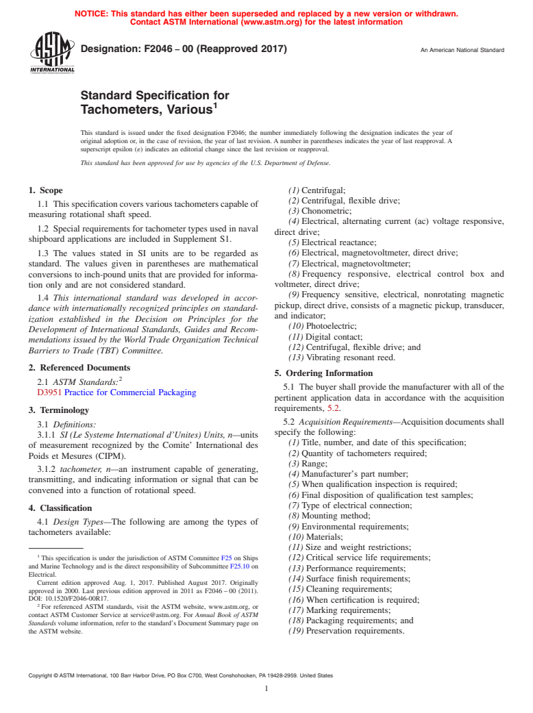
1.1 This specification covers various tachometers capable of measuring rotational shaft speed.
1.2 Special requirements for tachometer types used in naval shipboard applications are included in Supplement S1.
1.3 The values stated in SI units are to be regarded as standard. The values given in parentheses are mathematical conversions to inch-pound units that are provided for information only and are not considered standard.
1.4 This international standard was developed in accordance with internationally recognized principles on standardization established in the Decision on Principles for the Development of International Standards, Guides and Recommendations issued by the World Trade Organization Technical Barriers to Trade (TBT) Committee.
General Information
Buy Standard
Standards Content (Sample)
NOTICE: This standard has either been superseded and replaced by a new version or withdrawn.
Contact ASTM International (www.astm.org) for the latest information
Designation:F2046 −00 (Reapproved 2017) An American National Standard
Standard Specification for
Tachometers, Various
This standard is issued under the fixed designation F2046; the number immediately following the designation indicates the year of
original adoption or, in the case of revision, the year of last revision.Anumber in parentheses indicates the year of last reapproval.A
superscript epsilon (´) indicates an editorial change since the last revision or reapproval.
This standard has been approved for use by agencies of the U.S. Department of Defense.
1. Scope (1)Centrifugal;
(2)Centrifugal, flexible drive;
1.1 Thisspecificationcoversvarioustachometerscapableof
(3)Chonometric;
measuring rotational shaft speed.
(4)Electrical, alternating current (ac) voltage responsive,
1.2 Specialrequirementsfortachometertypesusedinnaval
direct drive;
shipboard applications are included in Supplement S1.
(5)Electrical reactance;
1.3 The values stated in SI units are to be regarded as (6)Electrical, magnetovoltmeter, direct drive;
(7)Electrical, magnetovoltmeter;
standard. The values given in parentheses are mathematical
conversions to inch-pound units that are provided for informa- (8) Frequency responsive, electrical control box and
voltmeter, direct drive;
tion only and are not considered standard.
(9)Frequency sensitive, electrical, nonrotating magnetic
1.4 This international standard was developed in accor-
pickup, direct drive, consists of a magnetic pickup, transducer,
dance with internationally recognized principles on standard-
and indicator;
ization established in the Decision on Principles for the
(10)Photoelectric;
Development of International Standards, Guides and Recom-
(11)Digital contact;
mendations issued by the World Trade Organization Technical
(12)Centrifugal, flexible drive; and
Barriers to Trade (TBT) Committee.
(13)Vibrating resonant reed.
2. Referenced Documents
5. Ordering Information
2.1 ASTM Standards:
5.1 Thebuyershallprovidethemanufacturerwithallofthe
D3951Practice for Commercial Packaging
pertinent application data in accordance with the acquisition
requirements, 5.2.
3. Terminology
5.2 Acquisition Requirements—Acquisitiondocumentsshall
3.1 Definitions:
specify the following:
3.1.1 SI (Le Systeme International d’Unites) Units, n—units
(1)Title, number, and date of this specification;
of measurement recognized by the Comite’ International des
(2)Quantity of tachometers required;
Poids et Mesures (CIPM).
(3)Range;
3.1.2 tachometer, n—an instrument capable of generating,
(4)Manufacturer’s part number;
transmitting, and indicating information or signal that can be
(5)When qualification inspection is required;
convened into a function of rotational speed.
(6)Final disposition of qualification test samples;
(7)Type of electrical connection;
4. Classification
(8)Mounting method;
4.1 Design Types—The following are among the types of
(9)Environmental requirements;
tachometers available:
(10)Materials;
(11)Size and weight restrictions;
This specification is under the jurisdiction ofASTM Committee F25 on Ships
(12)Critical service life requirements;
and Marine Technology and is the direct responsibility of Subcommittee F25.10 on
(13)Performance requirements;
Electrical.
(14)Surface finish requirements;
Current edition approved Aug. 1, 2017. Published August 2017. Originally
(15)Cleaning requirements;
approved in 2000. Last previous edition approved in 2011 as F2046–00 (2011).
DOI: 10.1520/F2046-00R17.
(16)When certification is required;
For referenced ASTM standards, visit the ASTM website, www.astm.org, or
(17)Marking requirements;
contact ASTM Customer Service at service@astm.org. For Annual Book of ASTM
(18)Packaging requirements; and
Standards volume information, refer to the standard’s Document Summary page on
the ASTM website. (19)Preservation requirements.
Copyright © ASTM International, 100 Barr Harbor Drive, PO Box C700, West Conshohocken, PA 19428-2959. United States
F2046−00 (2017)
6. Materials and Manufacture 11. Number of Tests and Retests
11.1 Test Specimens—The number of test specimens to be
6.1 Material Selection—The materials for all parts shall be
subjected to qualification testing shall depend on the tachom-
selected for long-term compatibility with the environment in
eter design. If each range is covered by a separate and distinct
which the tachometer will be installed or used.
design, a test specimen for each range will require testing. In
6.2 Material Inspection—Themanufacturershallberespon-
instances in which a singular design series may cover multiple
sible for ensuring that materials used are manufactured,
ranges and types, it is recommended that three test specimens
examined, and tested in accordance with the specifications and
betestedprovidedtheelectricalandmechanicalsimilaritiesare
standards as applicable.
approved by the buyer. In no case, however, should less than
three units, one unit each representing low, medium, and high
7. Physical Properties
ranges, be tested, regardless of design similarity.
7.1 Size and Weight—The buyer may have intended appli-
12. Test Methods
cations where size and weight are limited. Size and weight
12.1 Tests—All tests shall be performed in accordance with
limitations shall be specified in the acquisition requirements.
ASTM, American Society of Mechanical Engineers (ASME),
or industry standards as specified.
8. Performance Requirements
12.2 Test Data—All test data shall remain on file at the
8.1 Service Life—Thebuyermayhaveaminimumspecified
manufacturer’sfacilityforreviewbythebuyeruponrequest.It
serviceliferequirement.Criticalserviceliferequirementsshall
isrecommendedthattestdataberetainedinthemanufacturer’s
be specified in the acquisition requirements.
filesforatleastthreeyearsoraperiodoftimeacceptabletothe
8.2 Tachometer Performance—Performance tolerances are
buyer and manufacturer.
usually specified in percentage of range span. The following
13. Quality Assurance Provisions
performance characteristics and environmental exposures may
or may not be important to each buyer’s intended application.
13.1 Warranty:
(1)Accuracy,
13.1.1 Responsibility for Warranty—Unless otherwise
(2)Repeatability,
specified, the manufacturer is responsible for the following:
(3)Damping,
(1)All materials used to produce a unit and
(4)Temperature,
(2)Manufacturer will warrant his product to be free from
(5)Humidity,
defect of workmanship to produce the unit.
(6)Salt spray,
(7)Vibration,
14. Certification
(8)Shock, and
14.1 When specified in the purchase order or contract, the
(9)Electromagnetic interference (EMI).
buyer shall be furnished certification that samples representing
each lot have been either tested or inspected as directed in this
9. Workmanship, Finish, and Appearance
specification, and the requirements have been met. When
specified in the purchase order or contract, a report of the test
9.1 Cleaning, Finish, and Appearance—Any special
results shall be furnished.
cleaning, surface finish, and appearance requirements shall be
specified in the acquisition requirements.
15. Product Marking
15.1 User-specified product marking shall be listed in the
10. Inspection
acquisition requirements. The minimum data to be clearly
10.1 Classification of Inspections—The inspection require-
marked on each tachometer shall include the following:
ments specified herein are classified as follows:
(1)Manufacturer’s name,
(1)Qualification testing, and
(2)Manufacturer’s part number,
(2)Quality conformance testing.
(3)Serial number or lot number,
(4)Date of manufacture, and
10.2 Qualification Testing—Qualification test requirements
(5)Range.
shall be specified, where applicable. Test methods should be
identified for each design and performance characteristic
16. Packaging and Package Marking
specified. Test report documentation requirements should also
be specified. 16.1 Packaging of Product for Delivery—Product shall be
packaged for shipment in accordance with Practice D3951.
10.3 Quality Conformance Testing—Quality conformance
16.2 Anyspecialpreservation,packaging,orpackagemark-
inspection is accomplished when acceptance and qualification
ing requirements for shipment or storage shall be identified in
testing is satisfied by a previous acquisition or when the
the acquisition requirements.
product has demonstrated reliability in similar applications.
Quality conformance inspection is usually less intensive than
17. Keywords
acceptance and qualification, often verifying that samples of a
production lot meet a few critical performance requirements. 17.1 tachometer
F2046−00 (2017)
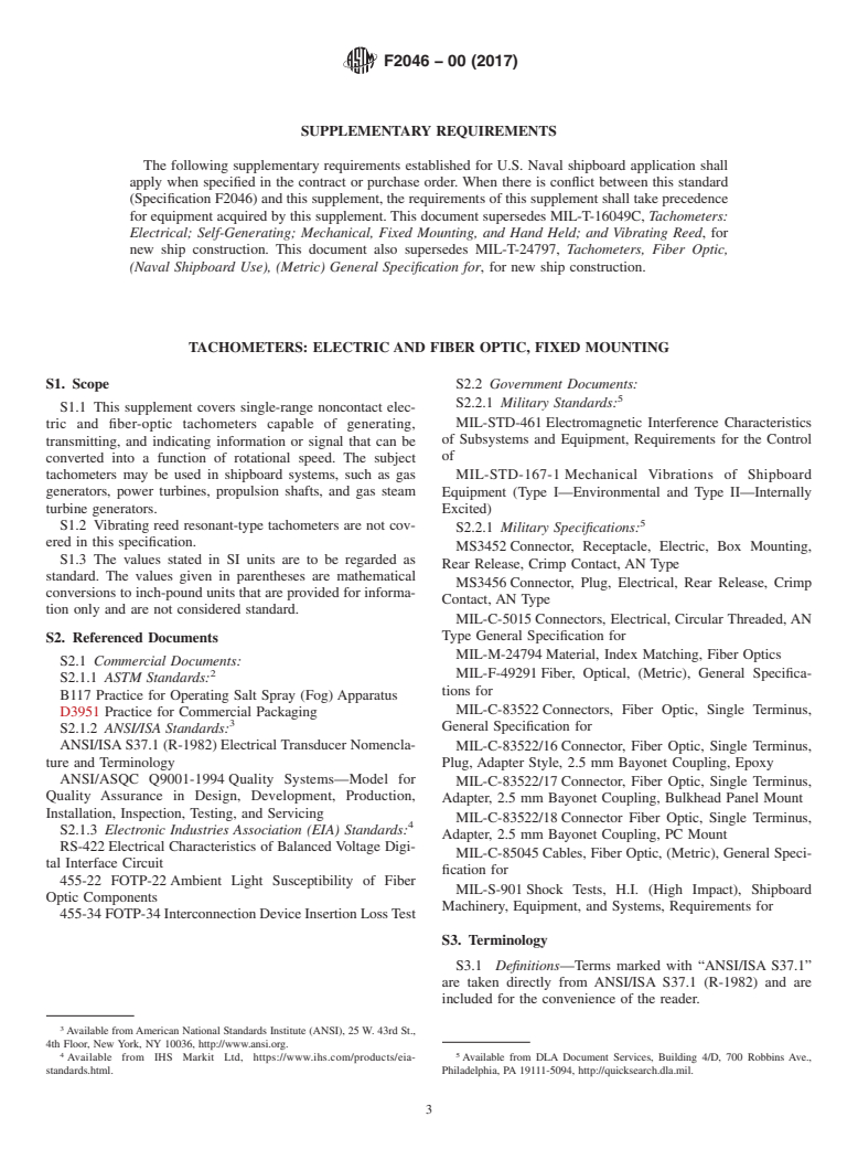
SUPPLEMENTARY REQUIREMENTS
The following supplementary requirements established for U.S. Naval shipboard application shall
apply when specified in the contract or purchase order. When there is conflict between this standard
(Specification F2046) and this supplement, the requirements of this supplement shall take precedence
for equipment acquired by this supplement.This document supersedes MIL-T-16049C, Tachometers:
Electrical; Self-Generating; Mechanical, Fixed Mounting, and Hand Held; and Vibrating Reed, for
new ship construction. This document also supersedes MIL-T-24797, Tachometers, Fiber Optic,
(Naval Shipboard Use), (Metric) General Specification for, for new ship construction.
TACHOMETERS: ELECTRIC AND FIBER OPTIC, FIXED MOUNTING
S1. Scope S2.2 Government Documents:
S2.2.1 Military Standards:
S1.1 This supplement covers single-range noncontact elec-
MIL-STD-461Electromagnetic Interference Characteristics
tric and fiber-optic tachometers capable of generating,
of Subsystems and Equipment, Requirements for the Control
transmitting, and indicating information or signal that can be
of
converted into a function of rotational speed. The subject
tachometers may be used in shipboard systems, such as gas MIL-STD-167-1 Mechanical Vibrations of Shipboard
generators, power turbines, propulsion shafts, and gas steam Equipment (Type I—Environmental and Type II—Internally
turbine generators.
Excited)
S1.2 Vibrating reed resonant-type tachometers are not cov-
S2.2.1 Military Specifications:
ered in this specification.
MS3452Connector, Receptacle, Electric, Box Mounting,
S1.3 The values stated in SI units are to be regarded as
Rear Release, Crimp Contact, AN Type
standard. The values given in parentheses are mathematical
MS3456Connector, Plug, Electrical, Rear Release, Crimp
conversions to inch-pound units that are provided for informa-
Contact, AN Type
tion only and are not considered standard.
MIL-C-5015Connectors, Electrical, Circular Threaded, AN
Type General Specification for
S2. Referenced Documents
MIL-M-24794Material, Index Matching, Fiber Optics
S2.1 Commercial Documents:
MIL-F-49291Fiber, Optical, (Metric), General Specifica-
S2.1.1 ASTM Standards:
tions for
B117 Practice for Operating Salt Spray (Fog) Apparatus
MIL-C-83522Connectors, Fiber Optic, Single Terminus,
D3951 Practice for Commercial Packaging
General Specification for
S2.1.2 ANSI/ISA Standards:
ANSI/ISAS37.1 (R-1982)Electrical Transducer Nomencla- MIL-C-83522/16Connector, Fiber Optic, Single Terminus,
ture and Terminology Plug, Adapter Style, 2.5 mm Bayonet Coupling, Epoxy
ANSI/ASQC Q9001-1994 Quality Systems—Model for
MIL-C-83522/17Connector, Fiber Optic, Single Terminus,
Quality Assurance in Design, Development, Production,
Adapter, 2.5 mm Bayonet Coupling, Bulkhead Panel Mount
Installation, Inspection, Testing, and Servicing
MIL-C-83522/18Connector Fiber Optic, Single Terminus,
S2.1.3 Electronic Industries Association (EIA) Standards:
Adapter, 2.5 mm Bayonet Coupling, PC Mount
RS-422Electrical Characteristics of Balanced Voltage Digi-
MIL-C-85045Cables, Fiber Optic, (Metric), General Speci-
tal Interface Circuit
fication for
455-22 FOTP-22Ambient Light Susceptibility of Fiber
MIL-S-901Shock Tests, H.I. (High Impact), Shipboard
Optic Components
Machinery, Equipment, and Systems, Requirements for
455-34FOTP-34InterconnectionDeviceInsertionLossTest
S3. Terminology
S3.1 Definitions—Terms marked with “ANSI/ISA S37.1”
are taken directly from ANSI/ISA S37.1 (R-1982) and are
included for the convenience of the reader.
Available fromAmerican National Standards Institute (ANSI), 25 W. 43rd St.,
4th Floor, New York, NY 10036, http://www.ansi.org.
4 5
Available from IHS Markit Ltd, https://www.ihs.com/products/eia- Available from DLA Document Services, Building 4/D, 700 Robbins Ave.,
standards.html. Philadelphia, PA 19111-5094, http://quicksearch.dla.mil.
F2046−00 (2017)
S3.1.1 ambient conditions, n—conditions, such as pressure S3.1.14 sensor head, n—the transduction element of a fiber
and temperature, of the medium surrounding the case of a optic tachometer that detects rotational speed by means of
sensor. changes in optical properties.
ANSI/ISA S37.1 S3.1.15 sheath, n—the protective covering of a sensor
element.
S3.1.2 calibration, n—test during which known values of
S3.1.16 signal conditioner, n—an electronic device that
measurandsareappliedtothesensorandcorrespondingoutput
makes the output signal from a transduction element compat-
readings are recorded under specific conditions.
ible with a readout system.
ANSI/ISA S37.1
S3.1.17 span,n—thealgebraicdifferencebetweenthelimits
S3.1.3 environmental conditions, n—specified external
of the measurement range.
conditions,suchasshock,vibration,andtemperature,towhich
S3.1.18 static error band, n—the maximum deviation from
a sensor may be exposed during shipping, storage, handling,
astraightlinedrawnthroughthecoordinatesofthelowerrange
and operation.
limit at specified sensor output, and the upper range limit at
ANSI/ISA S37.1
specified output expressed in percentage of sensor span.
S3.1.4 error, n—the error for a given value of the input
S3.1.19 supporting surface, n—surfaceonwhichtheequip-
variable (measurand) is the difference between the measured
ment is placed.
value of the output signal and the expected value of the output
S3.1.20 tachometer, n—an instrument capable of
signal.Theexpectedvalueoftheoutputsignalforanyvalueof
generating, transmitting, and indicating information or signal
themeasurandshallberepresentedbyastraightlinewhoseend
that can be converted into a function of rotational speed.
points are given by:
S3.1.21 target, n—description including items such as
S3.1.4.1 The specified value of the output signal at the
material, size, multiple reflectors, and surface features shall be
minimum input value of the measurand (for example, 4 mAat
as specified in the acquisition requirements.
the minimum specified rotational speed).
S3.1.22 warm-up time, n—the time required for a sensor to
operate within specified accuracy, repeatability, and other
S3.1.4.2 The specified value of the output signal at the
maximum inp
...
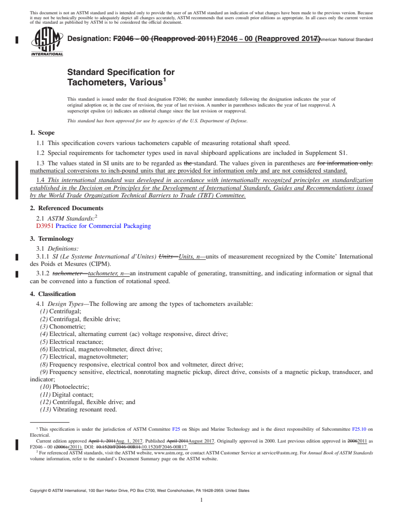
This document is not an ASTM standard and is intended only to provide the user of an ASTM standard an indication of what changes have been made to the previous version. Because
it may not be technically possible to adequately depict all changes accurately, ASTM recommends that users consult prior editions as appropriate. In all cases only the current version
of the standard as published by ASTM is to be considered the official document.
Designation: F2046 − 00 (Reapproved 2011) F2046 − 00 (Reapproved 2017)An American National Standard
Standard Specification for
Tachometers, Various
This standard is issued under the fixed designation F2046; the number immediately following the designation indicates the year of
original adoption or, in the case of revision, the year of last revision. A number in parentheses indicates the year of last reapproval. A
superscript epsilon (´) indicates an editorial change since the last revision or reapproval.
This standard has been approved for use by agencies of the U.S. Department of Defense.
1. Scope
1.1 This specification covers various tachometers capable of measuring rotational shaft speed.
1.2 Special requirements for tachometer types used in naval shipboard applications are included in Supplement S1.
1.3 The values stated in SI units are to be regarded as the standard. The values given in parentheses are for information only.
mathematical conversions to inch-pound units that are provided for information only and are not considered standard.
1.4 This international standard was developed in accordance with internationally recognized principles on standardization
established in the Decision on Principles for the Development of International Standards, Guides and Recommendations issued
by the World Trade Organization Technical Barriers to Trade (TBT) Committee.
2. Referenced Documents
2.1 ASTM Standards:
D3951 Practice for Commercial Packaging
3. Terminology
3.1 Definitions:
3.1.1 SI (Le Systeme International d’Unites) Units—Units, n—units of measurement recognized by the Comite’ International
des Poids et Mesures (CIPM).
3.1.2 tachometer—tachometer, n—an instrument capable of generating, transmitting, and indicating information or signal that
can be convened into a function of rotational speed.
4. Classification
4.1 Design Types—The following are among the types of tachometers available:
(1) Centrifugal;
(2) Centrifugal, flexible drive;
(3) Chonometric;
(4) Electrical, alternating current (ac) voltage responsive, direct drive;
(5) Electrical reactance;
(6) Electrical, magnetovoltmeter, direct drive;
(7) Electrical, magnetovoltmeter;
(8) Frequency responsive, electrical control box and voltmeter, direct drive;
(9) Frequency sensitive, electrical, nonrotating magnetic pickup, direct drive, consists of a magnetic pickup, transducer, and
indicator;
(10) Photoelectric;
(11) Digital contact;
(12) Centrifugal, flexible drive; and
(13) Vibrating resonant reed.
This specification is under the jurisdiction of ASTM Committee F25 on Ships and Marine Technology and is the direct responsibility of Subcommittee F25.10 on
Electrical.
Current edition approved April 1, 2011Aug. 1, 2017. Published April 2011August 2017. Originally approved in 2000. Last previous edition approved in 20062011 as
F2046 – 00 (2006).(2011). DOI: 10.1520/F2046-00R11.10.1520/F2046-00R17.
For referenced ASTM standards, visit the ASTM website, www.astm.org, or contact ASTM Customer Service at service@astm.org. For Annual Book of ASTM Standards
volume information, refer to the standard’s Document Summary page on the ASTM website.
Copyright © ASTM International, 100 Barr Harbor Drive, PO Box C700, West Conshohocken, PA 19428-2959. United States
F2046 − 00 (2017)
5. Ordering Information
5.1 The buyer shall provide the manufacturer with all of the pertinent application data in accordance with the acquisition
requirements, 5.2.
5.2 Acquisition Requirements—Acquisition documents shall specify the following:
(1) Title, number, and date of this specification;
(2) Quantity of tachometers required;
(3) Range;
(4) Manufacturer’s part number;
(5) When qualification inspection is required;
(6) Final disposition of qualification test samples;
(7) Type of electrical connection;
(8) Mounting method;
(9) Environmental requirements;
(10) Materials;
(11) Size and weight restrictions;
(12) Critical service life requirements;
(13) Performance requirements;
(14) Surface finish requirements;
(15) Cleaning requirements;
(16) When certification is required;
(17) Marking requirements;
(18) Packaging requirements; and
(19) Preservation requirements.
6. Materials and Manufacture
6.1 Material Selection—The materials for all parts shall be selected for long-term compatibility with the environment in which
the tachometer will be installed or used.
6.2 Material Inspection—The manufacturer shall be responsible for ensuring that materials used are manufactured, examined,
and tested in accordance with the specifications and standards as applicable.
7. Physical Properties
7.1 Size and Weight—The buyer may have intended applications where size and weight are limited. Size and weight limitations
shall be specified in the acquisition requirements.
8. Performance Requirements
8.1 Service Life—The buyer may have a minimum specified service life requirement. Critical service life requirements shall be
specified in the acquisition requirements.
8.2 Tachometer Performance—Performance tolerances are usually specified in percentage of range span. The following
performance characteristics and environmental exposures may or may not be important to each buyer’s intended application.
(1) Accuracy,
(2) Repeatability,
(3) Damping,
(4) Temperature,
(5) Humidity,
(6) Salt spray,
(7) Vibration,
(8) Shock, and
(9) Electromagnetic interference (EMI).
9. Workmanship, Finish, and Appearance
9.1 Cleaning, Finish, and Appearance—Any special cleaning, surface finish, and appearance requirements shall be specified in
the acquisition requirements.
10. Inspection
10.1 Classification of Inspections—The inspection requirements specified herein are classified as follows:
(1) Qualification testing, and
(2) Quality conformance testing.
F2046 − 00 (2017)
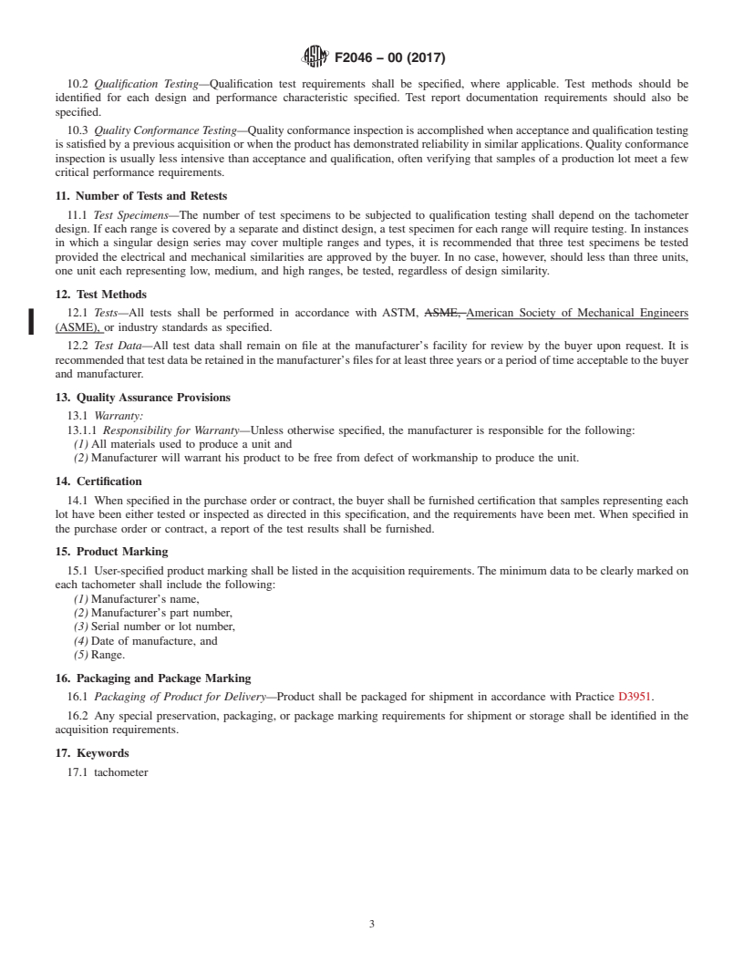
10.2 Qualification Testing—Qualification test requirements shall be specified, where applicable. Test methods should be
identified for each design and performance characteristic specified. Test report documentation requirements should also be
specified.
10.3 Quality Conformance Testing—Quality conformance inspection is accomplished when acceptance and qualification testing
is satisfied by a previous acquisition or when the product has demonstrated reliability in similar applications. Quality conformance
inspection is usually less intensive than acceptance and qualification, often verifying that samples of a production lot meet a few
critical performance requirements.
11. Number of Tests and Retests
11.1 Test Specimens—The number of test specimens to be subjected to qualification testing shall depend on the tachometer
design. If each range is covered by a separate and distinct design, a test specimen for each range will require testing. In instances
in which a singular design series may cover multiple ranges and types, it is recommended that three test specimens be tested
provided the electrical and mechanical similarities are approved by the buyer. In no case, however, should less than three units,
one unit each representing low, medium, and high ranges, be tested, regardless of design similarity.
12. Test Methods
12.1 Tests—All tests shall be performed in accordance with ASTM, ASME, American Society of Mechanical Engineers
(ASME), or industry standards as specified.
12.2 Test Data—All test data shall remain on file at the manufacturer’s facility for review by the buyer upon request. It is
recommended that test data be retained in the manufacturer’s files for at least three years or a period of time acceptable to the buyer
and manufacturer.
13. Quality Assurance Provisions
13.1 Warranty:
13.1.1 Responsibility for Warranty—Unless otherwise specified, the manufacturer is responsible for the following:
(1) All materials used to produce a unit and
(2) Manufacturer will warrant his product to be free from defect of workmanship to produce the unit.
14. Certification
14.1 When specified in the purchase order or contract, the buyer shall be furnished certification that samples representing each
lot have been either tested or inspected as directed in this specification, and the requirements have been met. When specified in
the purchase order or contract, a report of the test results shall be furnished.
15. Product Marking
15.1 User-specified product marking shall be listed in the acquisition requirements. The minimum data to be clearly marked on
each tachometer shall include the following:
(1) Manufacturer’s name,
(2) Manufacturer’s part number,
(3) Serial number or lot number,
(4) Date of manufacture, and
(5) Range.
16. Packaging and Package Marking
16.1 Packaging of Product for Delivery—Product shall be packaged for shipment in accordance with Practice D3951.
16.2 Any special preservation, packaging, or package marking requirements for shipment or storage shall be identified in the
acquisition requirements.
17. Keywords
17.1 tachometer
F2046 − 00 (2017)
SUPPLEMENTARY REQUIREMENTS
The following supplementary requirements established for U.S. Naval shipboard application shall
apply when specified in the contract or purchase order. When there is conflict between thethis standard
(Specification F2046) and this supplement, the requirements of this supplement shall take precedence
for equipment acquired by this supplement. This document supersedes MIL-T-16049C, Tachometers:
Electrical; Self-Generating; Mechanical, Fixed Mounting, and Hand Held; and Vibrating Reed, for
new ship construction. This document also supersedes MIL-T-24797, Tachometers, Fiber Optic,
(Naval Shipboard Use), (Metric) General Specification for, for new ship construction.
TACHOMETERS: ELECTRIC AND FIBER OPTIC, FIXED MOUNTING
S1. Scope
S1.1 This supplement covers single-range noncontact electric and fiber-optic tachometers capable of generating, transmitting,
and indicating information or signal that can be converted into a function of rotational speed. The subject tachometers may be used
in shipboard systems, such as gas generators, power turbines, propulsion shafts, and gas steam turbine generators.
S1.2 Vibrating reed resonant-type tachometers are not covered in this specification.
S1.3 The values stated in SI units are to be regarded as the standard. The values given in parentheses are for information
only.mathematical conversions to inch-pound units that are provided for information only and are not considered standard.
S2. Referenced Documents
S2.1 Commercial Documents:
S2.1.1 ASTM Standards:
B117 Practice for Operating Salt Spray (Fog) Apparatus
D3951 Practice for Commercial Packaging
S2.1.2 ANSI/ISA Standards:
ANSI/ISA S37.1 (R-1982) Electrical Transducer Nomenclature and Terminology
ANSI/ASQC Q9001-1994 Quality Systems—Model for Quality Assurance in Design, Development, Production, Installation,
Inspection, Testing, and Servicing
S2.1.3 Electronic Industries Association (EIA):(EIA) Standards:
RS-422 Electrical Characteristics of Balanced Voltage Digital Interface Circuit
455-22 FOTP-22 Ambient Light Susceptibility of Fiber Optic Components
455-34 FOTP-34 Interconnection Device Insertion Loss Test
Available from American National Standards Institute (ANSI), 25 W. 43rd St., 4th Floor, New York, NY 10036, http://www.ansi.org.
Available from Electronic Industries Alliance (EIA), 2500 Wilson Blvd., Arlington, VA 22201, http://www.ecaus.org/eia.IHS Markit Ltd, https://www.ihs.com/products/
eia-standards.html.
F2046 − 00 (2017)
S2.2 Government Documents:
S2.2.1 Military Standards:
MIL-STD-461 Electromagnetic Interference Characteristics of Subsystems and Equipment, Requirements for the Control of
MIL-STD-167-1 Mechanical Vibrations of Shipboard Equipment (Type I—Environmental and Type II—Internally Excited)
S2.2.1 Military Specifications:
MS3452 Connector, Receptacle, Electric, Box Mounting, Rear Release, Crimp Contact, AN Type
MS3456 Connector, Plug, Electrical, Rear Release, Crimp Contact, AN Type
MIL-C-5015 Connectors, Electrical, Circular Threaded, AN Type General Specification for
MIL-M-24794 Material, Index Matching, Fiber Optics
MIL-F-49291 Fiber, Optical, (Metric), General Specifications for
MIL-C-83522 Connectors, Fiber Optic, Single Terminus, General Specification for
MIL-C-83522/16 Connector, Fiber Optic, Single Terminus, Plug, Adapter Style, 2.5 mm Bayonet Coupling, Epoxy
MIL-C-83522/17 Connector, Fiber Optic, Single Terminus, Adapter, 2.5 mm Bayonet Coupling, Bulkhead Panel Mount
MIL-C-83522/18 Connector Fiber Optic, Single Terminus, Adapter, 2.5 mm Bayonet Coupling, PC Mount
MIL-C-85045 Cables, Fiber Optic, (Metric), General Specification for
MIL-S-901 Shock Tests, H.I. (High Impact), Shipboard Machinery, Equipment, and Systems, Requirements for
S3. Terminology
S3.1 Definitions—Terms marked with (ANSI/ISA S37.1)“ANSI/ISA S37.1” are taken directly from ANSI/ISA S37.1 (R-1982)
and are included for the convenience of the reader.
S3.1.1 ambient conditionsconditions, n—conditions, such as pressure and temperature, of the medium surrounding the case of
a sensorsensor.
(ANSI/ISA ANSI/ISA S37.1S37.1).
S3.1.2 calibrationcalibration, n—test during which known values of measurands are applied to the sensor and corresponding
output readings are recorded under specific conditionsconditions.
(ANSI/ISA ANSI/ISA S37.1S37.1).
S3.1.3 environmental conditionsconditions, n—specified external conditions, such as shock, vibration, and temperature, to
which a sensor may be exposed during shipping, storage, handling, and operationoperation.
(ANSI/ISA ANSI/ISA S37.1S37.1).
S3.1.4 errorerror, n—the error for a given value of the input variable (measurand) is the difference between the measured value
of the output signal and the expected value of the output signal. The expected value of the output signal for any value of the
measurand shall be represented by a straight line whose end points are given by:
S3.1.4.1 The specified value of the output signal at the minimum input value of the measurand (for example, 4 mA at the
minimum specified rotational speed).
S3.1.4.2 The specified value of the output signal at the maximum input value of the measurand (for example, 20 mA at the
maximum specified rotational speed).
S3.1.5 noncontact tachometertachometer, n—any type of tachometer that senses or responds to rotational speed without
physical contact or mechanical connection to the shaft being measured.
S3.1.6 operating environmental conditionsconditions, n—environmental conditions during exposure to which
...
Questions, Comments and Discussion
Ask us and Technical Secretary will try to provide an answer. You can facilitate discussion about the standard in here.