


ASTM E681-09(2015)
(Test Method)Standard Test Method for Concentration Limits of Flammability of Chemicals (Vapors and Gases)
Standard Test Method for Concentration Limits of Flammability of Chemicals (Vapors and Gases)
SIGNIFICANCE AND USE
5.1 The LFL and UFL of gases and vapors define the range of flammable concentrations in air.
5.2 This method measures the LFL and UFL for upward (and partially outward) flame propagation. The limits for downward flame propagation are narrower.
5.3 Limits of flammability may be used to determine guidelines for the safe handling of volatile chemicals. They are used particularly in assessing ventilation requirements for the handling of gases and vapors. NFPA 69 provides guidance for the practical use of flammability limit data, including the appropriate safety margins to use.
5.4 As discussed in Brandes and Ural,4 there is a fundamental difference between the ASTM and European methods for flammability determination. The ASTM methods aim to produce the best representation of flammability parameters, and rely upon the safety margins imposed by the application standards, such as NFPA 69. On the other hand, European test methods aim to result in a conservative representation of flammability parameters. For example, in this standard, LFL is the calculated average of the lowest go and highest no-go concentrations while the European test methods report the LFL as the minimum of the 5 highest no-go concentrations.
Note 2: For hydrocarbons, the break point between nonflammability and flammability occurs over a narrow concentration range at the lower flammability limit, but the break point is less distinct at the upper limit. For materials found to be non-reproducible per 13.1.1 that are likely to have large quenching distances and may be difficult to ignite, such as ammonia and certain halogenated hydrocarbon, the lower and upper limits of these materials may both be less distinct. That is, a wider range exists between flammable and nonflammable concentrations (see Annex A1).
SCOPE
1.1 This test method covers the determination of the lower and upper concentration limits of flammability of chemicals having sufficient vapor pressure to form flammable mixtures in air at atmospheric pressure at the test temperature. This test method may be used to determine these limits in the presence of inert dilution gases. No oxidant stronger than air should be used.
Note 1: The lower flammability limit (LFL) and upper flammability limit (UFL) are sometimes referred to as the lower explosive limit (LEL) and the upper explosive limit (UEL), respectively. However, since the terms LEL and UEL are also used to denote concentrations other than the limits defined in this test method, one must examine the definitions closely when LEL and UEL values are reported or used.
1.2 This test method is based on electrical ignition and visual observations of flame propagation. Users may experience problems if the flames are difficult to observe (for example, irregular propagation or insufficient luminescence in the visible spectrum), if the test material requires large ignition energy, or if the material has large quenching distances.
1.3 Annex A1 provides a modified test method for materials (such as certain amines, halogenated materials, and the like) with large quenching distances which may be difficult to ignite.
1.4 In other situations where strong ignition sources (such as direct flame ignition) is considered credible, the use of a test method employing higher energy ignition source in a sufficiently large pressure chamber (analogous, for example, to the methods in Test Method E2079 for measuring limiting oxygen concentration) may be more appropriate. In this case, expert advice may be necessary.
1.5 The flammability limits depend on the test temperature and pressure. This test method is limited to an initial pressure of the local ambient or less, with a practical lower pressure limit of approximately 13 kPa (100 mm Hg). The maximum practical operating temperature of this equipment is approximately 150°C.
1.6 The values stated in SI units are to be regarded as standard. No other units of measurement ar...
General Information
Buy Standard
Standards Content (Sample)
NOTICE: This standard has either been superseded and replaced by a new version or withdrawn.
Contact ASTM International (www.astm.org) for the latest information
Designation: E681 − 09 (Reapproved 2015)
Standard Test Method for
Concentration Limits of Flammability of Chemicals (Vapors
and Gases)
This standard is issued under the fixed designation E681; the number immediately following the designation indicates the year of
original adoption or, in the case of revision, the year of last revision. A number in parentheses indicates the year of last reapproval. A
superscript epsilon (´) indicates an editorial change since the last revision or reapproval.
1. Scope 1.6 The values stated in SI units are to be regarded as
standard. No other units of measurement are included in this
1.1 This test method covers the determination of the lower
standard.
and upper concentration limits of flammability of chemicals
having sufficient vapor pressure to form flammable mixtures in
1.7 This test method should be used to measure and describe
air at atmospheric pressure at the test temperature. This test
the properties of materials, products, or assemblies in response
method may be used to determine these limits in the presence
to heat and flame under controlled laboratory conditions and
of inert dilution gases. No oxidant stronger than air should be
should not be used to describe or appraise the fire hazard or fire
used.
risk of materials, products, or assemblies under actual fire
conditions. However, results of this test method may be used as
NOTE 1—The lower flammability limit (LFL) and upper flammability
elements of a fire risk assessment that takes into account all of
limit (UFL) are sometimes referred to as the lower explosive limit (LEL)
and the upper explosive limit (UEL), respectively. However, since the
the factors pertinent to an assessment of the fire hazard of a
terms LEL and UEL are also used to denote concentrations other than the
particular end use.
limits defined in this test method, one must examine the definitions closely
1.8 This standard may involve hazardous materials,
when LEL and UEL values are reported or used.
operations, and equipment. This standard does not purport to
1.2 This test method is based on electrical ignition and
address all of the safety concerns, if any, associated with its
visual observations of flame propagation. Users may experi-
use. It is the responsibility of the user of this standard to
ence problems if the flames are difficult to observe (for
establish appropriate safety and health practices and deter-
example, irregular propagation or insufficient luminescence in
mine the applicability of regulatory limitations prior to use.
the visible spectrum), if the test material requires large ignition
Specific precautionary statements are given in Section 8
energy, or if the material has large quenching distances.
1.3 Annex A1 provides a modified test method for materials
2. Referenced Documents
(such as certain amines, halogenated materials, and the like)
2.1 ASTM Standards:
with large quenching distances which may be difficult to ignite.
E171 Practice for Conditioning and Testing Flexible Barrier
1.4 In other situations where strong ignition sources (such
Packaging
as direct flame ignition) is considered credible, the use of a test
E582 Test Method for Minimum Ignition Energy and
method employing higher energy ignition source in a suffi-
Quenching Distance in Gaseous Mixtures
ciently large pressure chamber (analogous, for example, to the
E1445 Terminology Relating to Hazard Potential of Chemi-
methods in Test Method E2079 for measuring limiting oxygen
cals
concentration) may be more appropriate. In this case, expert
E1515 Test Method for Minimum Explosible Concentration
advice may be necessary.
of Combustible Dusts
1.5 The flammability limits depend on the test temperature
E2079 Test Methods for Limiting Oxygen (Oxidant) Con-
and pressure. This test method is limited to an initial pressure
centration in Gases and Vapors
of the local ambient or less, with a practical lower pressure
2.2 NFPA Standard:
limit of approximately 13 kPa (100 mm Hg). The maximum
NFPA 69 Standard on Explosion Prevention Systems
practical operating temperature of this equipment is approxi-
mately 150°C.
1 2
This test method is under the jurisdiction of ASTM Committee E27 on Hazard For referenced ASTM standards, visit the ASTM website, www.astm.org, or
Potential of Chemicals and is the direct responsibility of Subcommittee E27.04 on contact ASTM Customer Service at service@astm.org. For Annual Book of ASTM
Flammability and Ignitability of Chemicals. Standards volume information, refer to the standard’s Document Summary page on
Current edition approved Feb. 1, 2015. Published March 2015. Originally the ASTM website.
approved in 1979. Last previous edition approved in 2009 as E681 – 09. DOI: Available from National Fire Protection Association (NFPA), 1 Batterymarch
10.1520/E0681-09R15. Park, Quincy, MA 02169-7471, http://www.nfpa.org.
Copyright © ASTM International, 100 Barr Harbor Drive, PO Box C700, West Conshohocken, PA 19428-2959. United States
E681 − 09 (2015)
and flammability occurs over a narrow concentration range at the lower
3. Terminology
flammability limit, but the break point is less distinct at the upper limit.
3.1 Definitions:
For materials found to be non-reproducible per 13.1.1 that are likely to
3.1.1 lower limit of flammability or lower flammable limit have large quenching distances and may be difficult to ignite, such as
ammonia and certain halogenated hydrocarbon, the lower and upper limits
(LFL)—the minimum concentration of a combustible sub-
of these materials may both be less distinct. That is, a wider range exists
stance that is capable of propagating a flame in a homogeneous
between flammable and nonflammable concentrations (see Annex A1).
mixture of the combustible and a gaseous oxidizer under the
specified conditions of test.
6. Interferences
3.1.2 propagation of flame— as used in this test method, the
6.1 This test method is not applicable to certain readily
upward and outward movement of the flame front from the
oxidized chemicals. If significant oxidation takes place when
ignition source to the vessel walls or at least to within 13 mm
the vapors are mixed with air, unreliable results may be
( ⁄2 in.) of the wall, which is determined by visual observation.
obtained. Flow systems designed to minimize hold-up time
By outward, it is meant a flame front that has a horizontal
may be required for such materials.
component to the movement away from the ignition source.
6.2 Measured flammable limits are influenced by flame
3.1.3 upper limit of flammability or upper flammable limit
quenching effects of the test vessel walls. The test vessel
(UFL)—the maximum concentration of a combustible sub-
employed in this test method is of sufficient size to eliminate
stance that is capable of propagating a flame in a homogeneous
the effects of the flame quenching for most materials (and
mixture of the combustible and a gaseous oxidizer under the
conditions).
specified conditions of test.
NOTE 3—There may be quenching effects, particularly on tests run at
3.2 Additional terms can be found in Terminology E1445.
subambient pressures. For materials that may be difficult to ignite (see
Note 2), tests in a larger vessel or different ignition sources (see Annex
4. Summary of Test Method
A1, 12-L flask) may show flame propagation that is not seen in the 5-L
flask with spark or exploding wire igniters. This test method is a small
4.1 A uniform mixture of a gas or vapor with air is ignited
scale test and this possible limitation must be considered in hazard
in a closed vessel, and the upward and outward propagation of
assessments.
the flame away from the ignition source is noted by visual
6.3 The oxygen concentration in the air has an important
observation. The concentration of the flammable component is
effect on the UFL. Typically, room air is used. If cylinder air is
varied between trials until the composition that will just sustain
used to simulate room air it must have an oxygen concentration
propagation of the flame is determined.
of 20.94 6 0.1 %. Reconstituted air in cylinders has variability
in the oxygen concentration and must be verified for oxygen
5. Significance and Use
concentration.
5.1 The LFL and UFL of gases and vapors define the range
of flammable concentrations in air.
7. Apparatus
5.2 This method measures the LFL and UFL for upward
7.1 Fig. 1 is a schematic diagram of the apparatus; details
(and partially outward) flame propagation. The limits for
and dimensions are presented in Appendix X1. The apparatus
downward flame propagation are narrower.
consists of a glass test vessel, an insulated chamber equipped
5.3 Limits of flammability may be used to determine guide-
with a source of controlled-temperature air, an ignition device
lines for the safe handling of volatile chemicals. They are used
with an appropriate power supply, a magnetic stirrer, and a
particularly in assessing ventilation requirements for the han-
cover equipped with the necessary operating connections and
dling of gases and vapors. NFPA 69 provides guidance for the
components.
practical use of flammability limit data, including the appro-
7.2 If tests are to be conducted at an elevated temperature,
priate safety margins to use.
the test vessel may be heated as described in Appendix X1. The
5.4 As discussed in Brandes and Ural, there is a fundamen- heating system must be capable of controlling the gas tempera-
tal difference between the ASTM and European methods for
ture inside the test vessel to within 63°C both temporally and
flammability determination. The ASTM methods aim to pro- spatially. An appropriate device such as a thermocouple must
duce the best representation of flammability parameters, and
be used to monitor the gas temperature within the test vessel.
rely upon the safety margins imposed by the application Active (connected) volumes beyond the test vessel itself should
standards, such as NFPA 69. On the other hand, European test
be held above the condensation temperature of all components
methods aim to result in a conservative representation of in the material being tested. Electrical heating tapes must be
flammability parameters. For example, in this standard, LFL is
employed for heating components to the desired temperature.
the calculated average of the lowest go and highest no-go
NOTE 4—Certain bare wire thermocouples may cause catalytic oxida-
concentrations while the European test methods report the LFL
tion of test vapors, as evidenced by a persistent high-temperature
as the minimum of the 5 highest no-go concentrations.
excursion of the temperature reading. If this occurs, other thermocouple
NOTE 2—For hydrocarbons, the break point between nonflammability
materials should be employed.
7.3 Pressure Transducer—A low-range pressure transducer
may be used for the purpose of making partial pressure
Brandes, E., and Erdem, A. U., “Towards a Global Standard for Flammability
additions of gases and vapors to the test vessel. The transducer
Determination,” 42nd Annual Loss Prevention Symposium, New Orleans, LA, April
2008. and its signal conditioning/amplifying electronics should have
E681 − 09 (2015)
FIG. 1 Schematic Diagram of Test Apparatus
an accuracy, precision and repeatability sufficient to accurately rupture. Methods for estimating initial test concentrations,
resolve the required changes in the gas partial pressure for the discussed in Appendix X2, Appendix X3, and Appendix X4,
component used in lowest concentration at the appropriate test may be employed to ensure that initial trials are conducted at
temperature. The transducer should be protected from defla- concentrations less than the LFL or greater than the UFL.
gration pressures by means of an isolation valve. An error
8.2.3 In rare instances, particularly in the upper limit tests,
analysis must be performed to demonstrate that the internal self-ignition may be encountered when air is rapidly introduced
volume of the pressure gage and piping will not significantly
into the partially evacuated test vessel containing the vaporized
affect the test mixture. sample. Valves permitting remote operation, changes in sample
and air introduction sequences, simple shields, and other
8. Safety Precautions
techniques may be employed to ensure safe operations.
8.1 Tests should not be conducted in this apparatus with
8.2.4 The test area should be equipped with electrical
oxidizers stronger than air, since explosion violence increases
interlocks to prevent activation of the ignition source unless
as oxidizer strength increases. Do not use oxygen, nitrous adequate shielding is in place.
oxide, nitrogen dioxide, chlorine, etc., in this glass apparatus.
8.3 Tests should not be conducted on thermally unstable
Extra care must be used when working with compounds that
materials that might undergo explosive decomposition reac-
are potential oxidizers.
tions.
8.2 Adequate shielding must be provided to prevent injury
8.4 Tests should be conducted in a fume hood or other
in the event of equipment rupture due to both implosions and
ventilated area to prevent personal exposure to toxic chemicals
explosions. A metal enclosure, such as that recommended in
or combustion products.
Appendix X1, is one method suitable for this purpose.
8.2.1 Implosion of the test vessel at high vacuum levels is 8.5 Precautions must be taken to ensure that the high-
possible; therefore, all evacuations must be made with the voltage spark ignition source does not contact temperature or
required shielding to protect against flying fragments. pressure-measuring devices or other conductive paths that
8.2.2 Energetic explosions may be produced if tests are could create an electrical hazard to personnel or instrumenta-
made at concentrations within the flammable range, between tion outside the shielded area. Careful attention to electrical
the LFL and UFL. The glass test vessel, equipped with a lightly insulation integrity can reduce the possibility of hazard. Dis-
held or loose cover, vents most explosions adequately. connects for all instrumentation lines will provide positive
Nevertheless, shielding is required to protect against vessel protection.
E681 − 09 (2015)
9. Calibration 10.4 Double-check to make certain that all safety precau-
tions have been taken.
9.1 Accurate determination of the flask volume is necessary
for the calculation of flammable limits when the sample 10.5 Procedure for Sample Introduction As a Liquid:
measurement is on a weight or volume basis.
10.5.1 Ensure that sample and any combustion products
9.1.1 Determine the total volume of the flask as follows:
from previous runs have been removed. This may
...
This document is not an ASTM standard and is intended only to provide the user of an ASTM standard an indication of what changes have been made to the previous version. Because
it may not be technically possible to adequately depict all changes accurately, ASTM recommends that users consult prior editions as appropriate. In all cases only the current version
of the standard as published by ASTM is to be considered the official document.
Designation: E681 − 09 E681 − 09 (Reapproved 2015)
Standard Test Method for
Concentration Limits of Flammability of Chemicals (Vapors
and Gases)
This standard is issued under the fixed designation E681; the number immediately following the designation indicates the year of
original adoption or, in the case of revision, the year of last revision. A number in parentheses indicates the year of last reapproval. A
superscript epsilon (´) indicates an editorial change since the last revision or reapproval.
1. Scope
1.1 This test method covers the determination of the lower and upper concentration limits of flammability of chemicals having
sufficient vapor pressure to form flammable mixtures in air at atmospheric pressure at the test temperature. This test method may
be used to determine these limits in the presence of inert dilution gases. No oxidant stronger than air should be used.
NOTE 1—The lower flammability limit (LFL) and upper flammability limit (UFL) are sometimes referred to as the lower explosive limit (LEL) and
the upper explosive limit (UEL), respectively. However, since the terms LEL and UEL are also used to denote concentrations other than the limits defined
in this test method, one must examine the definitions closely when LEL and UEL values are reported or used.
1.2 This test method is based on electrical ignition and visual observations of flame propagation. Users may experience
problems if the flames are difficult to observe (for example, irregular propagation or insufficient luminescence in the visible
spectrum), if the test material requires large ignition energy, or if the material has large quenching distances.
1.3 Annex A1 provides a modified test method for materials (such as certain amines, halogenated materials, and the like) with
large quenching distances which may be difficult to ignite.
1.4 In other situations where strong ignition sources (such as direct flame ignition) is considered credible, the use of a test
method employing higher energy ignition source in a sufficiently large pressure chamber (analogous, for example, to the methods
in Test Method E2079 for measuring limiting oxygen concentration) may be more appropriate. In this case, expert advice may be
necessary.
1.5 The flammability limits depend on the test temperature and pressure. This test method is limited to an initial pressure of the
local ambient or less, with a practical lower pressure limit of approximately 13 kPa (100 mm Hg). The maximum practical
operating temperature of this equipment is approximately 150°C.
1.6 The values stated in SI units are to be regarded as standard. No other units of measurement are included in this standard.
1.7 This test method should be used to measure and describe the properties of materials, products, or assemblies in response
to heat and flame under controlled laboratory conditions and should not be used to describe or appraise the fire hazard or fire risk
of materials, products, or assemblies under actual fire conditions. However, results of this test method may be used as elements
of a fire risk assessment that takes into account all of the factors pertinent to an assessment of the fire hazard of a particular end
use.
1.8 This standard may involve hazardous materials, operations, and equipment. This standard does not purport to address all
of the safety concerns, if any, associated with its use. It is the responsibility of the user of this standard to establish appropriate
safety and health practices and determine the applicability of regulatory limitations prior to use. Specific precautionary statements
are given in Section 8
2. Referenced Documents
2.1 ASTM Standards:
E171 Practice for Conditioning and Testing Flexible Barrier Packaging
E582 Test Method for Minimum Ignition Energy and Quenching Distance in Gaseous Mixtures
This test method is under the jurisdiction of ASTM Committee E27 on Hazard Potential of Chemicals and is the direct responsibility of Subcommittee E27.04 on
Flammability and Ignitability of Chemicals.
Current edition approved Oct. 1, 2009Feb. 1, 2015. Published January 2010March 2015. Originally approved in 1979. Last previous edition approved in 20042009 as
E681 – 04.E681 – 09. DOI: 10.1520/E0681-09.10.1520/E0681-09R15.
For referenced ASTM standards, visit the ASTM website, www.astm.org, or contact ASTM Customer Service at service@astm.org. For Annual Book of ASTM Standards
volume information, refer to the standard’s Document Summary page on the ASTM website.
Copyright © ASTM International, 100 Barr Harbor Drive, PO Box C700, West Conshohocken, PA 19428-2959. United States
E681 − 09 (2015)
E1445 Terminology Relating to Hazard Potential of Chemicals
E1515 Test Method for Minimum Explosible Concentration of Combustible Dusts
E2079 Test Methods for Limiting Oxygen (Oxidant) Concentration in Gases and Vapors
2.2 NFPA Standard:
NFPA 69 Standard on Explosion Prevention Systems
3. Terminology
3.1 Definitions:
3.1.1 lower limit of flammability or lower flammable limit (LFL)—the minimum concentration of a combustible substance that
is capable of propagating a flame in a homogeneous mixture of the combustible and a gaseous oxidizer under the specified
conditions of test.
3.1.2 propagation of flame— as used in this test method, the upward and outward movement of the flame front from the ignition
source to the vessel walls or at least to within 13 mm ( ⁄2 in.) of the wall, which is determined by visual observation. By outward,
it is meant a flame front that has a horizontal component to the movement away from the ignition source.
3.1.3 upper limit of flammability or upper flammable limit (UFL)—the maximum concentration of a combustible substance that
is capable of propagating a flame in a homogeneous mixture of the combustible and a gaseous oxidizer under the specified
conditions of test.
3.2 Additional terms can be found in Terminology E1445.
4. Summary of Test Method
4.1 A uniform mixture of a gas or vapor with air is ignited in a closed vessel, and the upward and outward propagation of the
flame away from the ignition source is noted by visual observation. The concentration of the flammable component is varied
between trials until the composition that will just sustain propagation of the flame is determined.
5. Significance and Use
5.1 The LFL and UFL of gases and vapors define the range of flammable concentrations in air.
5.2 This method measures the LFL and UFL for upward (and partially outward) flame propagation. The limits for downward
flame propagation are narrower.
5.3 Limits of flammability may be used to determine guidelines for the safe handling of volatile chemicals. They are used
particularly in assessing ventilation requirements for the handling of gases and vapors. NFPA 69 provides guidance for the practical
use of flammability limit data, including the appropriate safety margins to use.
5.4 As discussed in Brandes and Ural, there is a fundamental difference between the ASTM and European methods for
flammability determination. The ASTM methods aim to produce the best representation of flammability parameters, and rely upon
the safety margins imposed by the application standards, such as NFPA 69. On the other hand, European test methods aim to result
in a conservative representation of flammability parameters. For example, in this standard, LFL is the calculated average of the
lowest go and highest no-go concentrations while the European test methods report the LFL as the minimum of the 5 highest no-go
concentrations.
NOTE 2—For hydrocarbons, the break point between nonflammability and flammability occurs over a narrow concentration range at the lower
flammability limit, but the break point is less distinct at the upper limit. For materials found to be non-reproducible per 13.1.1 that are likely to have large
quenching distances and may be difficult to ignite, such as ammonia and certain halogenated hydrocarbon, the lower and upper limits of these materials
may both be less distinct. That is, a wider range exists between flammable and nonflammable concentrations (see Annex A1).
6. Interferences
6.1 This test method is not applicable to certain readily oxidized chemicals. If significant oxidation takes place when the vapors
are mixed with air, unreliable results may be obtained. Flow systems designed to minimize hold-up time may be required for such
materials.
6.2 Measured flammable limits are influenced by flame quenching effects of the test vessel walls. The test vessel employed in
this test method is of sufficient size to eliminate the effects of the flame quenching for most materials (and conditions).
NOTE 3—There may be quenching effects, particularly on tests run at subambient pressures. For materials that may be difficult to ignite (see Note 2),
tests in a larger vessel or different ignition sources (see Annex A1, 12-L flask) may show flame propagation that is not seen in the 5-L flask with spark
or exploding wire igniters. This test method is a small scale test and this possible limitation must be considered in hazard assessments.
Available from National Fire Protection Association (NFPA), 1 Batterymarch Park, Quincy, MA 02169-7471, http://www.nfpa.org.
Brandes, ElizabetgE., and Erdem, A. Ural, "TowardsU., “Towards a Global Standard for Flammability Determination,"Determination,” 42nd Annual Loss Prevention
Symposium, New Orleans, LA, April 20082008.
E681 − 09 (2015)
6.3 The oxygen concentration in the air has an important effect on the UFL. Typically, room air is used. If cylinder air is used
to simulate room air it must have an oxygen concentration of 20.94 6 0.1 %. Reconstituted air in cylinders has variability in the
oxygen concentration and must be verified for oxygen concentration.
7. Apparatus
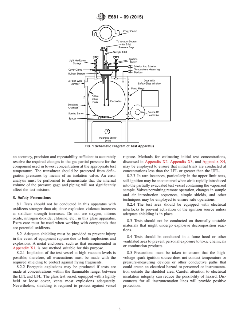
7.1 Fig. 1 is a schematic diagram of the apparatus; details and dimensions are presented in Appendix X1. The apparatus consists
of a glass test vessel, an insulated chamber equipped with a source of controlled-temperature air, an ignition device with an
appropriate power supply, a magnetic stirrer, and a cover equipped with the necessary operating connections and components.
7.2 If tests are to be conducted at an elevated temperature, the test vessel may be heated as described in Appendix X1. The
heating system must be capable of controlling the gas temperature inside the test vessel to within 63°C both temporally and
spatially. An appropriate device such as a thermocouple must be used to monitor the gas temperature within the test vessel. Active
(connected) volumes beyond the test vessel itself should be held above the condensation temperature of all components in the
material being tested. Electrical heating tapes must be employed for heating components to the desired temperature.
NOTE 4—Certain bare wire thermocouples may cause catalytic oxidation of test vapors, as evidenced by a persistent high-temperature excursion of the
temperature reading. If this occurs, other thermocouple materials should be employed.
7.3 Pressure Transducer—A low-range pressure transducer may be used for the purpose of making partial pressure additions
of gases and vapors to the test vessel. The transducer and its signal conditioning/amplifying electronics should have an accuracy,
precision and repeatability sufficient to accurately resolve the required changes in the gas partial pressure for the component used
in lowest concentration at the appropriate test temperature. The transducer should be protected from deflagration pressures by
means of an isolation valve. An error analysis must be performed to demonstrate that the internal volume of the pressure gage and
piping will not significantly affect the test mixture.
8. Safety Precautions
8.1 Tests should not be conducted in this apparatus with oxidizers stronger than air, since explosion violence increases as
oxidizer strength increases. Do not use oxygen, nitrous oxide, nitrogen dioxide, chlorine, etc., in this glass apparatus. Extra care
must be used when working with compounds that are potential oxidizers.
8.2 Adequate shielding must be provided to prevent injury in the event of equipment rupture due to both implosions and
explosions. A metal enclosure, such as that recommended in Appendix X1, is one method suitable for this purpose.
FIG. 1 Schematic Diagram of Test Apparatus
E681 − 09 (2015)
8.2.1 Implosion of the test vessel at high vacuum levels is possible; therefore, all evacuations must be made with the required
shielding to protect against flying fragments.
8.2.2 Energetic explosions may be produced if tests are made at concentrations within the flammable range, between the LFL
and UFL. The glass test vessel, equipped with a lightly held or loose cover, vents most explosions adequately. Nevertheless,
shielding is required to protect against vessel rupture. Methods for estimating initial test concentrations, discussed in Appendix X2,
Appendix X3, and Appendix X4, may be employed to ensure that initial trials are conducted at concentrations less than the LFL
or greater than the UFL.
8.2.3 In rare instances, particularly in the upper limit tests, self-ignition may be encountered when air is rapidly introduced into
the partially evacuated test vessel containing the vaporized sample. Valves permitting remote operation, changes in sample and air
introduction sequences, simple shields, and other techniques may be employed to ensure safe operations.
8.2.4 The test area should be equipped with electrical interlocks to prevent activation of the ignition source unless adequate
shielding is in place.
8.3 Tests should not be conducted on thermally unstable materials that might undergo explosive decomposition reactions.
8.4 Tests should be conducted in a fume hood or other ventilated area to prevent personal exposure to toxic chemicals or
combustion products.
8.5 Precautions must be taken to ensure that the high-voltage spark ignition source does not contact temperature or
pressure-measuring devices or other conductive paths that could create an electrical hazard to personnel or instrumentation outside
the shielded area. Careful attention to electrical insulation integrity can reduce the possibility of hazard. Disconnects for all
instrumentation lines will provide positive protection.
9. Calibration
9.1 Accurate determination of the flask volume is necessary for the calculation of flammable limits when the sample
measurement is on a weight or volume basis.
9.1.1 De
...
Questions, Comments and Discussion
Ask us and Technical Secretary will try to provide an answer. You can facilitate discussion about the standard in here.