

ASTM F3530-22
(Guide)Standard Guide for Additive Manufacturing - Design - Post-Processing for Metal PBF-LB
General Information
- Abstract
SCOPE
1.1 This document provides guidance to designers who are considering the use of metal Laser Powder Bed Fusion (PBF-LB) method for their products. This guide outlines the following post-processing operations that can be considered after completion of a build on a metal additive manufacturing system:
1.1.1 Powder removal,
1.1.2 Thermal post-processing,
1.1.3 Build platform removal,
1.1.4 Support removal,
1.1.5 Machining, and
1.1.6 Surface finishing.
1.2 The topics of non-destructive testing (NDT) and inspection are beyond the scope of this document as it requires a comprehensive guide in its own right. Also, outside the scope are other metal PBF processes such as powder bed fusion – electron beam (PBF-EB) and hybrid additive manufacturing (methods combining additive manufacturing and subtractive manufacturing technologies in a single machine).
1.3 With respect to existing ISO/ASTM standards, this guide is positioned between ISO/ASTM 52910 and process-specific design guidelines such as ISO/ASTM 52911-1.
1.4 This standard does not purport to address all of the safety concerns, if any, associated with its use. It is the responsibility of the user of this standard to establish appropriate safety, health, and environmental practices and determine the applicability of regulatory limitations prior to use.
1.5 This international standard was developed in accordance with internationally recognized principles on standardization established in the Decision on Principles for the Development of International Standards, Guides and Recommendations issued by the World Trade Organization Technical Barriers to Trade (TBT) Committee.
- Status
- Published
- Publication Date
- 31-Mar-2022
- Technical Committee
- F42 - Additive Manufacturing Technologies
- Drafting Committee
- F42.04 - Design
Overview
ASTM F3530-22: Standard Guide for Additive Manufacturing – Design – Post-Processing for Metal PBF-LB provides comprehensive guidance to designers leveraging metal Laser Powder Bed Fusion (PBF-LB) additive manufacturing. Developed by ASTM International, this standard outlines crucial post-processing operations that directly impact the quality, performance, and manufacturability of PBF-LB metal parts. By covering operations such as powder removal, thermal post-processing, build platform removal, support removal, machining, and surface finishing, ASTM F3530-22 serves as a key reference for optimizing workflows in metal additive manufacturing.
This guide is positioned between high-level additive manufacturing standards (e.g., ISO/ASTM 52910) and more process-specific design guidelines (e.g., ISO/ASTM 52911-1), making it essential for those seeking practical, actionable design and post-processing advice in metal PBF-LB.
Key Topics
ASTM F3530-22 addresses the following core post-processing operations for metal PBF-LB:
- Powder Removal: Techniques and design considerations to ensure complete and safe removal of metal powder from both external and internal features, minimizing health, safety, and quality risks.
- Thermal Post-Processing: Guidance on processes such as stress relief and heat treatment to optimize part properties, reduce residual stress, and address defects like porosity, cracking, and undesirable microstructures common in PBF-LB builds.
- Build Platform Removal: Evaluates methods such as wire EDM, band saw, and manual removal, with design tips to facilitate efficient and accurate separation from the build platform.
- Support Removal: Recommendations on design adjustments to minimize the need for supports, ease their removal, and prevent associated surface damage or powder entrapment.
- Machining and Surface Finishing: Covers strategies for incorporating machining allowances, datum features, and fixturing solutions so that critical surfaces meet tight tolerances and required finishes.
The standard emphasizes the importance of considering these post-processing steps early in the design phase to improve part quality, reduce lead time, prevent costly redesigns, and fully leverage the benefits of additive manufacturing.
Applications
This standard guide is valuable in a broad range of metal additive manufacturing applications where PBF-LB is employed, including:
- Aerospace and Automotive: Optimizing lightweight, complex parts where reliability and precision are critical.
- Medical Devices: Ensuring safe removal of residual powder especially for implantable parts, and achieving biocompatible surfaces through appropriate post-processing.
- Tooling and Industrial Equipment: Producing robust, custom or low-volume components with enhanced mechanical properties.
Design engineers, manufacturing specialists, and quality control professionals use ASTM F3530-22 to:
- Streamline the workflow from 3D modeling to finished part.
- Proactively mitigate risks related to powder handling, post-build distortion, and part inconsistency.
- Select suitable post-processing equipment and plan operations within facility capabilities.
- Enhance safety by establishing proper powder handling and removal protocols.
Related Standards
To provide a holistic approach to metal additive manufacturing, refer to these closely linked standards:
- ISO/ASTM 52900: Additive manufacturing – General principles – Terminology.
- ISO/ASTM 52910: Additive manufacturing – Design – Requirements, guidelines, and recommendations.
- ISO/ASTM 52911-1: Additive manufacturing – Design – Part 1: Laser-based powder bed fusion of metals.
- ASTM F42 Standards: Series of documents from ASTM’s Committee on Additive Manufacturing Technologies offering related guidelines on materials, processes, and quality assurance.
ASTM F3530-22 supports improved design for post-processing in metal PBF-LB, helping organizations achieve consistent, high-quality results in metal additive manufacturing while aligning with international best practices and regulatory requirements.
For designers and engineers seeking to optimize their approach to post-processing in metal 3D printing, this guide is an invaluable resource for ensuring both process efficiency and final part performance.
Get Certified
Connect with accredited certification bodies for this standard

DVS-ZERT GmbH
German welding certification society.
CARES (UK Certification Authority for Reinforcing Steels)
UK certification for reinforcing steels and construction.
EWF/IIW (European/International Welding Federation)
International welding personnel certification.
Sponsored listings
Frequently Asked Questions
ASTM F3530-22 is a guide published by ASTM International. Its full title is "Standard Guide for Additive Manufacturing - Design - Post-Processing for Metal PBF-LB". This standard covers: SCOPE 1.1 This document provides guidance to designers who are considering the use of metal Laser Powder Bed Fusion (PBF-LB) method for their products. This guide outlines the following post-processing operations that can be considered after completion of a build on a metal additive manufacturing system: 1.1.1 Powder removal, 1.1.2 Thermal post-processing, 1.1.3 Build platform removal, 1.1.4 Support removal, 1.1.5 Machining, and 1.1.6 Surface finishing. 1.2 The topics of non-destructive testing (NDT) and inspection are beyond the scope of this document as it requires a comprehensive guide in its own right. Also, outside the scope are other metal PBF processes such as powder bed fusion – electron beam (PBF-EB) and hybrid additive manufacturing (methods combining additive manufacturing and subtractive manufacturing technologies in a single machine). 1.3 With respect to existing ISO/ASTM standards, this guide is positioned between ISO/ASTM 52910 and process-specific design guidelines such as ISO/ASTM 52911-1. 1.4 This standard does not purport to address all of the safety concerns, if any, associated with its use. It is the responsibility of the user of this standard to establish appropriate safety, health, and environmental practices and determine the applicability of regulatory limitations prior to use. 1.5 This international standard was developed in accordance with internationally recognized principles on standardization established in the Decision on Principles for the Development of International Standards, Guides and Recommendations issued by the World Trade Organization Technical Barriers to Trade (TBT) Committee.
SCOPE 1.1 This document provides guidance to designers who are considering the use of metal Laser Powder Bed Fusion (PBF-LB) method for their products. This guide outlines the following post-processing operations that can be considered after completion of a build on a metal additive manufacturing system: 1.1.1 Powder removal, 1.1.2 Thermal post-processing, 1.1.3 Build platform removal, 1.1.4 Support removal, 1.1.5 Machining, and 1.1.6 Surface finishing. 1.2 The topics of non-destructive testing (NDT) and inspection are beyond the scope of this document as it requires a comprehensive guide in its own right. Also, outside the scope are other metal PBF processes such as powder bed fusion – electron beam (PBF-EB) and hybrid additive manufacturing (methods combining additive manufacturing and subtractive manufacturing technologies in a single machine). 1.3 With respect to existing ISO/ASTM standards, this guide is positioned between ISO/ASTM 52910 and process-specific design guidelines such as ISO/ASTM 52911-1. 1.4 This standard does not purport to address all of the safety concerns, if any, associated with its use. It is the responsibility of the user of this standard to establish appropriate safety, health, and environmental practices and determine the applicability of regulatory limitations prior to use. 1.5 This international standard was developed in accordance with internationally recognized principles on standardization established in the Decision on Principles for the Development of International Standards, Guides and Recommendations issued by the World Trade Organization Technical Barriers to Trade (TBT) Committee.
ASTM F3530-22 is classified under the following ICS (International Classification for Standards) categories: 25.030 - Additive manufacturing. The ICS classification helps identify the subject area and facilitates finding related standards.
ASTM F3530-22 is available in PDF format for immediate download after purchase. The document can be added to your cart and obtained through the secure checkout process. Digital delivery ensures instant access to the complete standard document.
Standards Content (Sample)
This international standard was developed in accordance with internationally recognized principles on standardization established in the Decision on Principles for the
Development of International Standards, Guides and Recommendations issued by the World Trade Organization Technical Barriers to Trade (TBT) Committee.
Designation: F3530 − 22
Standard Guide for
Additive Manufacturing — Design — Post-Processing for
Metal PBF-LB
This standard is issued under the fixed designation F3530; the number immediately following the designation indicates the year of
original adoption or, in the case of revision, the year of last revision. A number in parentheses indicates the year of last reapproval. A
superscript epsilon (´) indicates an editorial change since the last revision or reapproval.
1. Scope 2. Referenced Documents
1.1 This document provides guidance to designers who are 2.1 Thefollowingexistingstandardsarerelevanttoadditive
considering the use of metal Laser Powder Bed Fusion manufacturing (AM) design.
(PBF-LB) method for their products. This guide outlines the
2.2 ISO/ASTM Standards:
following post-processing operations that can be considered
52900 Additive manufacturing — General Principles —
after completion of a build on a metal additive manufacturing
Fundamental and vocabulary
system:
52910 Additive manufacturing — Design — Requirements,
1.1.1 Powder removal,
guidelines and recommendations
1.1.2 Thermal post-processing,
52911-1 Additivemanufacturing—Design—Part1:Laser-
1.1.3 Build platform removal,
based powder bed fusion of metals
1.1.4 Support removal,
1.1.5 Machining, and
3. Terminology
1.1.6 Surface finishing.
3.1 Terminology relating to additive manufacturing in ISO/
1.2 The topics of non-destructive testing (NDT) and inspec-
ASTM 52900 shall apply.
tion are beyond the scope of this document as it requires a
3.2 Acronyms:
comprehensive guide in its own right. Also, outside the scope
3.2.1 3D—3-dimensional
are other metal PBF processes such as powder bed fusion –
electron beam (PBF-EB) and hybrid additive manufacturing 3.2.2 AM—additive manufacturing
(methods combining additive manufacturing and subtractive
3.2.3 CAD—computer aided design
manufacturing technologies in a single machine).
3.2.4 CMM—coordinate measurement machine
1.3 With respect to existing ISO/ASTM standards, this
3.2.5 CNC—computerized numerical control
guide is positioned between ISO/ASTM 52910 and process-
3.2.6 ECM—electro-chemical machining
specific design guidelines such as ISO/ASTM 52911-1.
1.4 This standard does not purport to address all of the 3.2.7 EDM—electrical discharge machining
safety concerns, if any, associated with its use. It is the
3.2.8 FEA—finite element analysis
responsibility of the user of this standard to establish appro-
3.2.9 HAZ—heat affected zone
priate safety, health, and environmental practices and deter-
mine the applicability of regulatory limitations prior to use.
3.2.10 HIP—hot isostatic pressing
1.5 This international standard was developed in accor-
3.2.11 LM—laser melting
dance with internationally recognized principles on standard-
3.2.12 PBF-LB—powder bed fusion – laser beam
ization established in the Decision on Principles for the
Development of International Standards, Guides and Recom-
3.2.13 NDT—non-destructive testing
mendations issued by the World Trade Organization Technical
3.2.14 RFPE—reference free part encapsulation
Barriers to Trade (TBT) Committee.
3.2.15 XCT—X-ray computed tomography
This guide is under the jurisdiction of ASTM Committee F42 on Additive
Manufacturing Technologies and is the direct responsibility of Subcommittee For referenced ASTM standards, visit the ASTM website, www.astm.org, or
F42.04 on Design. contact ASTM Customer Service at service@astm.org. For Annual Book of ASTM
Current edition approved April 1, 2022. Published July 2022. DOI: 10.1520/ Standards volume information, refer to the standard’s Document Summary page on
F3530-22. the ASTM website.
Copyright © ASTM International, 100 Barr Harbor Drive, PO Box C700, West Conshohocken, PA 19428-2959. United States
F3530 − 22
4. AM Process Workflow 5.2 If the build and post-processing requirements are not
considered at the design stage, there is a higher likelihood that
4.1 Similar to other production methods, the first step in the
redesigns and rebuilds of the part may be necessary. The
AM workflow begins with an idea of the part to build.AnAM
consequences of a redesign or rebuild may include:
part must start in a software that describes its geometry.
5.2.1 Increased costs due to failed builds or repeated builds
4.1.1 Commonly, the AM process workflow is often per-
due to quality issues.
ceived to be as simple as modelling the CAD geometry and
5.2.2 Reduced functionality, for example, as-built surface
transferring it to the machine to obtain the final part. In
roughness or parts not to tolerance.
practice, there are a number of other key steps involved in the
5.2.3 Wasted resources if builds fail and parts have to be
process as illustrated in Fig. 1. Although the workflow is
scrapped.
illustrated linearly, this is often iterative, for example, lessons
5.2.4 Waste of material and resources from support struc-
learned from a preliminary build or post-process feedback into
tures and sacrificial build features.
a new iteration of the design for manufacture or build prepa-
ration. See ISO/ASTM 52910 for more detail. 5.2.5 Time delays caused by unsuccessful builds or exces-
sive post-processing.
4.1.2 AM has its own manufacturing constraints.Therefore,
the next stages consider reducing risk in the design for the
5.3 MostAM parts will need some form of post-processing
specific AM process.
after the actual ‘build’ process has taken place. Depending on
4.1.3 Once the part is built, it is post-processed. This
the AM process used, the geometry of a part, and the desired
generally involves de-powdering, thermal post-processing,
properties, different post-processing may be needed. Typical
build platform and support removal, machining critical inter-
operationscarriedoutafterametalPBF-LBbuildaredescribed
faces (if required) and surface finishing etc.
in the next sections with their challenges and design consider-
4.1.4 Finally, the part could be inspected using various
ations. Description of how each process is carried out with
contact and non-contact methods such as structured light/laser
common methods can be found in the appendix.
scanning, XCT and CMM etc. These steps are outside the
scope of this document.
6. Powder Removal
6.1 Background:
5. The Importance of Design for AM Post-Processing
6.1.1 PBF processes fill the whole volume of the build
5.1 To design optimum parts to be built using AM, consid-
chamber with powder during a build, irrespective of the part’s
eration must be given to the manufacturing process. Every step
geometry. Therefore, once the AM build is complete, the part
downstream in the process should be considered during the
must be removed from the powder and will require de-
design stage (even if it is being outsourced to a bureau service)
powdering. The removed powder can be sieved and recycled
to ensure a suitable outcome is achieved. Fig. 2 depicts some
for the next build.
of the downstream requirements to be taken into consideration
6.1.2 Powder removal may also be critical to eliminate
in the design phase. Taking care of these requirements will not
contamination of other systems or patient requirements for
only improve the final product but also reduce the associated
implanted parts.
health and safety risks due to powders, part design, and
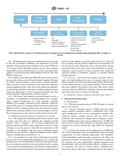
operators exposure to machines when post-processing. 6.2 Challenges in Powder Removal:
FIG. 1 Typical AM Workflow and Post-Processing Steps (Copyright MTC, all rights reserved)
F3530 − 22
FIG. 2 AM Workflow—Input of the AM Downstream Processes to be Considered at the Design Stage (Copyright MTC, all rights re-
served)
6.2.1 Residuepowdercanposeahealthandsafetyissuedue enclose a large volume of powder in the center of it. This will
to the risk of ignition, inhalation, and ingestion. It can also be very heavy and may make it difficult or even hazardous to
interfere with post-processing methods such as wire EDM. See tilt the part by hand. Moreover, such a tilt operation will put
9.4 for more detail. Residual powder can also fuse together unwanted loads on the part walls. Some platforms are imple-
duringHIPorstressreliefprocessesaswellasconsolidateafter menting a suction system to remove powder from within the
getting wet and drying after build platform removal with wire enclosed volume to minimize exposure to powder during
EDM or band saw. powder removal.
6.2.2 Hollow parts built with PBF-LB fusion will be full of 6.3.3 In Fig. 4, slots have been added to the part where it
loose powder when removed from the build chamber. The lack meets the build platform for ease of powder removal; this
of powder removal features such as holes, internal channels, allowspowdertoberemovedwithminimaltilting.Thenumber
lattice structures, slots or clearances can hinder this operation of slots allows powder to be removed quickly. Slots are built
causing trapped powder. This risk can be reduced by appropri- into stock added to the bottom of the part. This stock will be
ate part design together with robust cleaning methods and part removed with wire EDM after building, meaning the finished
inspection. Borescope or XCT inspection methods are often part will be the same as before the redesign.
used to identify trapped powder in these features.
6.4 Design for Powder Removal Checklist—See Table 2.
6.2.3 The choice and method of powder removal can be a
challenge. A combination of blasting medium (for example, 7. Thermal Post-Processing
argon, sodium bicarbonate etc.) and cleaning solutions/
7.1 Background
methods (for example, deionised water, ultrasonic) might be
7.1.1 Thermal post-processing of PBF-LB parts is carried
needed.Thechoiceofcleaningsolutioncanalsobemademore
out for two reasons:
difficult if CNC machining fluids must be removed. Compat-
7.1.1.1 Reduce Residual Stresses—High local heat input
ibility of the cleaning solution to the material might be critical.
causes material expansion which is constrained, due to the
The cleaning process may also be used to passivate the part.
rapid solidification rates in the surrounding material. This
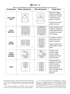
6.3 Mitigating Powder Removal Challenges by Design: constraint induces residual stresses and can lead to part
6.3.1 Thedesignmustincludepowderreleasefeatures,such distortion. The continuous melting and re-melting of previ-
as holes and slots that are sufficient for adequate powder ously solidified layers also causes residual stress. In PBF-LB,
removal. Table 1 displays a list of design adjustments for stresses in the center of the material are typically compressive
powder removal and offers some suggestions for how to adopt compared to stresses towards the edge which are generally
a design to ease the process. Note that the orientation of the tensile.
examples is not defined, with the aim to illustrate generic 7.1.1.2 Due to the nature of the build process of PBF-LB,
powder removal situations without the influence of the support the as-built component may not immediately meet the design
removal considerations described in 9.4. requirements for their intended application. The feedstock,
6.3.2 An example of a part being redesigned for powder build atmosphere, and processing parameters all affect the
removal can be seen in the following figures. Fig. 3 shows the generation of defects. In particular, the repeated re-melting of
part placed on the build platform in the desired build orienta- the material can cause undesirable material properties and
tion.Assuming the powder is not removed by powder vacuum, microstructure, with as-built structures likely to contain exces-
it will require the build platform to be tilted by a large angle to sive porosity and lack of fusion defects. Thermal post-
ensureproperremovalofpowder.Thegeometryofthepartwill processing aims to alleviate or minimize defects and improve
F3530 − 22
A
TABLE 1 Design Adjustments for Powder Recovery (Content adapted from Kranz et al, Ref (1) )
the material properties. Note that the particular thermal pro- 7.1.2.1 Porosity—Occurs due to entrapped gas or lack-of-
cesses used for post-processing vary for material and build fusion due to irregular powder shape, insufficient material
process. Table 3 summarizes the thermal processes and their spreading or insufficient heat (Fig. 5). Gas trapped in powders
effects. from the atomization powder may also cause porosity. Lack of
7.1.2 Common problems in PBF-LB as-built structures fusion defects often occur due to unsuitable build parameters
which may be reduced by thermal post-processing include: and so thermal processing should be a last resort to fix these
F3530 − 22
TABLE 1 Continued
A
The boldface numbers in parentheses refer to the list of references at the end of this standard.
defects. Keyhole porosity occurs due to bubbles of gas getting 7.2 Challenges in Thermal Post-processing:
trappedunderneaththesurfaceofapartcausingsphericalpores 7.2.1 The type of heat treatment process and their cycle
under the surface. Shrinkage porosity may also occur upon properties depend on the material and should be performed as
solidificationofliquidmetalduetovolumereduction.Reactive recommended in the corresponding standard for each material.
powders are sensitive to ambient humidity and may absorb Materials will react differently depending on their as-built
moisture from surrounding air causing poor build quality. condition and so the standards should only be used as a guide.
7.1.2.2 Cracking—Occurs due to many factors such as Heat treatment can change the microstructure of PBF-LB built
insufficientmaterialbeingavailableduringsolidificationdueto materials and so the designer should consider what microstruc-
low material feed or powder scattering due to laser intensity or ture is required to achieve the desired end-item properties.
insufficient re-melting of previous layers occurs (Fig. 6). Consideration of the sequence of thermal processing is also
7.1.2.3 Undesirable Microstructure—Re-melting of previ- important, to avoid part distortion or fusing, or both, of any
ous layers can lead to long, columnar grains. Depending on the residual powder. Every effort should be made to remove loose
material, distance from substrate and the processing powder prior to stress relief. The challenges to be considered
parameters, the previous layer will be partially re-melted with before performing thermal post-processing are summarized as
the un-melted portion acting as a substrate for the growth of follows.
grains. Since grain growth follows the thermal gradient of the 7.2.1.1 Part Quality:
build, smaller, equiaxed grains are often found at the top layer (1) If the quality of the inert atmosphere is poor, or
due the slower cooling rate and no re-melting. Volumetrically, unknown,oxidationmayoccur.Hightemperaturesincreasethe
this grain structure constitutes a very small fraction of the rate of reaction of materials with environmental gases and
overall part volume, the majority of the microstructure being contaminants. The engineer should ensure good cleanliness of
dendritic in nature. The microstructure affects properties such partsandthefurnaceandsharingheatcycleswithuncleanparts
as the hardness, ductility, and strength. A fully equiaxed should be avoided. Consider wrapping the parts and build
microstructure may be achieved through recrystallization. platform in a sacrificial material with a higher oxygen affinity
F3530 − 22
FIG. 3 Original Design Part Oriented on Build Platform. Orientation may require the build platform to be tilted to remove powder. (Copy-
right MTC, all rights reserved. DRAMA was funded by UK Research and Innovation through the Industrial Strategy Challenge Fund and
supported by the Aerospace Technology Institute)
FIG. 4 Redesigned Part with Slots Added to the Part where it Meets the Build Platform for Powder Removal. The stock section (orange)
is intended to be removed by wire EDM after the build. (Copyright MTC, all rights reserved. DRAMA was funded by UK Research and
Innovation through the Industrial Strategy Challenge Fund and supported by the Aerospace Technology Institute)
than the part itself (stainless steel foil type 321, for example), (3) Highly pressurized inert gas expands with high tem-
to shield the previously exposed surfaces from possible oxida- perature and so internal gas pores may re-open during HIP.
tion. Do not puncture the foil, aim for a close fit, but not Although rare, gas porosity can act as a stress site post-HIP.To
gas-tight; see Fig. 7. Decoy parts may also be placed into the minimize this, avoid high temperature processes post-HIP if
furnace to absorb volatile contaminants (oxygen, moisture, possible and avoid high-temperatures in service. HIP is gener-
carbon, nitrogen, etc.) before the component does. Gravity acts ally used to improve part density and improve fatigue life by
on softened material during high-temperature processing and minimizing pores.
may result in sagging if overhangs are un-supported. (4) While selecting suppliers, a series of accreditations and
(2) For materials highly sensitive to oxidation, it may be standards will be stated as a representation of the quality and
desired to perform thermal post-processing under vacuum, repeatabilityoftheirservices.TableX1.1providesdescriptions
along with a foil wrap. Oxidation resistant alloys (Ni-base of some of the most common examples.
alloysforexample)areheattreatedinairandsothecomponent 7.2.1.2 Surface Defects—It is recommended to HIP prior to
material must be considered when selecting the most appro- any machining because HIP will not close surface-connected
priate heat treat parameters. pores. Cracks on the surface offer a way for air to infiltrate the
F3530 − 22
TABLE 2 Design Considerations Checklist
Design Consideration Description
Hollow sections Access into hollow spaces inside a part to ensure all loose powder can be successfully
removed is crucial. The holes/slots could be sealed later by a weld or epoxy if required.
Large sections enclosing powder Powder removal features could be added into the design; these can be incorporated to the
stock material connecting the assembly to the build platform as shown in Fig. 4. This will
allow powder removal without tilting the entire build.
Enclosed volumes consideration Parts should be designed and oriented on the build platform in such a manner that powder
can be removed from any enclosed volume. Powder should not be present in further post-
process operations such as thermal post-processing or build platform removal.
Internal channels/cavities The length and the cross-section of any internal channels and cavities should be
considered during design for ease in powder removal. Larger radii can be used for internal
features instead of corners. Cavities with line of sight can easily be accessed and cleared
of powder by compressed air, blasting media, or other methods such as wire.
Support structures Where possible, support structures should be avoided to reduce the risk of trapped powder.
TABLE 3 Summary of Thermal Processes and their Purpose for AM Components
Stress relief Minimizes or eliminates build induced residual stress to nucleate grains in a stress-free condition.
HIP Can close out internal porosity if not connected to the surface.
Homogenization, solution Modify the microstructure in the case of solid-solution strengthened alloys or nucleate and grow
treatment, age precipitates to obtain the desired mechanical properties.
FIG. 5 Micrograph Indicating Porosity and Lack of Fusion Observe in an AM Sample (2)
part during high temperature post-processing. This can be within that area. Direction of quenching should be performed
avoided by performing a vacuum furnace evacuation followed along the largest part axis to avoid distortion during liquid
by inert gas backfill. quench.
7.2.1.3 Accuracy—Uneven thermal gradients and furnace 7.2.1.4 Operation Sequence—In order to minimize compo-
cooling rates result in loss of geometric conformity causing nent distortion, it is recommended to perform thermal post-
distortion.Distortioncontrolisimprovedbyspecifyingfurnace processing before the part removal from the build platform.
ramp and cool rates in a heat treatment specification. In The cycles used and their order is material and process
situations where precision is paramount, enquire about the dependentandsotherecommendationsintherelevantstandard
equipment’s temperature uniformity volume and keep the part should be observed. Gas pores which are closed via HIP may
F3530 − 22
FIG. 6 Delamination and Cracking in PBF-LB Sample (3)
FIG. 7 Wrapping of Parts in a Box (Copyright MTC, all rights reserved)
re-open during subsequent heat treatments, high temperature (1) Selecting the appropriate thermal post-processing cycle
cycles may also alter the microstructure and effects of subse- needs to balance the benefits gained from a dedicated HIP
quent treatments and so the sequence of cycles should be cycle against the potential reduction in cost from using a
carefully considered. standard “coach” heat treatment cycle (coach cycle generally
7.2.1.5 Part Handling: refers to consolidation of different lots from different custom-
(1) Contamination from touching the part prior to heat ers together in one HIP cycle).
treatment may impact the material properties. The part should (2) A shared thermal cycle is regularly the most cost
be handled by the build platform where possible. effective option. If a dedicated cycle is required, the cost per
(2) For components above the safe manual handling limit cycle will increase.
lifting features will need to be incorporated into the design for 7.2.1.7 Lead Time—Thermal post-processing is a multistage
safe loading and unloading. process which increases lead-time. The time required for
7.2.1.6 Cost: thermal post-processing is component (geometry, material,
F3530 − 22
end-use) dependent. If no lead time improvement over tradi- ers understand the impact of thermal post-processing on part
tional manufacturing is to be achieved, it should be considered performance/quality and highlight the considerations before
if the design improvements of AM are worth it over cast or performing thermal post-processing. The following guidelines
forged components. are advisory only.
7.3 Mitigating Thermal Post-Processing Challenges by De-
8. Build Platform Removal
sign:
7.3.1 As HIPing is unable to close surface connected
8.1 Metal AM components are essentially welded to the
defects, the designer may wish to add extra material for
build platform in metal PBF-LB and therefore require removal
removal to account for this as well.
prior to certain post-processing steps. It should be noted that in
7.3.2 Depending on the material, particular heat treatment
some cases it is beneficial to post process parts on the build
equipment may be required and the size of the equipment
platform, for example, machining. The most common pro-
should be considered early on in the design stage. There needs
cesses for removing the build platform are: wire EDM, band
to be adequate space around the component in the furnace and
saw, and manual removal.
partsneedtobeloadedaccordingtothefurnacemanufacturer’s
8.2 The selection of the method depends on the availability
guidelines.
of the process for the size of the components, as well as:
7.3.3 Thermal treatment providers will use thermocouples
8.2.1 Complexity—Wire EDM provides the capability to
to monitor the temperature profiles of the components going
remove parts and supports with a complex profile, while parts
throughacycle.Bestpositionforathermocoupleplacementon
with a small surface area of contact with the build platform can
a component should be considered; this typically corresponds
be removed manually.
to the thickest wall sections.
8.2.2 Time Versus Quality and Cost—Wire EDM is a slower
7.3.4 Leftover, entrapped metal powder in components
process than band saw, but the surface quality and cost of the
might become an issue during thermal processing, as it can
build platform removal is higher.
consolidate in undesirable places. This could happen in fea-
tures such as internal channels, or cavities during a HIP cycle.
8.3 Mitigating Wire EDM Build Platform Removal Chal-
7.3.5 Part distortion may occur during thermal post-
lenges by Design:
processing. To minimize any such adverse effects, factors such
8.3.1 It is a relatively slow process.
as part orientation and how the part will be supported in the
8.3.1.1 Reducing the volume of material to cut through will
furnace must be considered.
also reduce the processing time. Choosing different materials
7.4 Design for Thermal Post-Processing Checklist: and process parameters for wire EDM may also reduce the
7.4.1 The guidelines in Table 4 are intended to help design- processing time.
TABLE 4 Design Considerations Checklist for Performing Thermal Post–Processing
Design Consideration Description
Stock material Parts may distort with thermal post-processing and may go out of the required tolerance.
Stock material can be added to the areas prone to distortion and can then be machined to
the required accuracy. Suitable simulation approaches may be utilized to predict the
amount of distortion.
Material properties Thermal post-processing may affect the mechanical properties of materials and therefore
should be accounted for during the design stage. The composition will affect how the
material responds to the whole AM process. Phase diagrams and cooling curves for each
material should be consulted for indications of material properties expected after thermal
post-processing.
Thin-walled parts Thin-walled parts may distort during thermal post-processing and will need careful
consideration. Distortion may be avoided by thickening sections and adding ribbing for
instance. Suitable simulation approaches may be utilized to predict the amount of distortion.
Temperature monitoring Best position for a thermocouple placement on a component should be considered. This
consideration may include adding features in the design to accommodate a thermocouple
or a sacrificial anchoring location alongside the build. Fig. 8 shows possible thermocouple
placement locations with their expected outcome.
Trapped powder Features should be added to the design to allow ease in powder removal as unwanted
powder can consolidate in internal cavities.
Supports To minimize part distortion during thermal post-processing, factors such as part orientation
and how the part will be supported in the furnace must be considered.
Build platform The build platform offers support to the part, preventing distortion and allowing easier
handling. Therefore, it should remain attached until after thermal post-processing If
components on a build platform require different heat treatments, the build plan should be
designed to allow the build platform to be carefully sectioned, leaving the parts attached. If
the build platform is a different alloy than the parts, parts removal prior to post-build thermal
processing may be required.
F3530 − 22
FIG. 8 Temperature Monitoring—Possible Thermocouple Locations (Copyright MTC, all rights reserved)
8.3.2 It can take a number of passes to obtain a high quality 8.3.6.1 Once cut, the parts should fall away from the wire.
finish, although a single pass may be acceptable. Parts enclosed in others can be secured to other components to
8.3.2.1 Consider the boundaries for tolerances and surface prevent them from rattling around and contacting the wire.
finish requirements to identify whether multiple passes are
8.3.7 Large parts can cause the build platform to distort
acceptable.
which may lead to the cut being out of tolerance or the wire
8.3.3 Multiple passes will require additional workholding
colliding with the build platform.
features on the component so that it can be held in the Wire
8.3.7.1 Additional stock material can be added between the
EDM machine once the build platform has been cut off.
part and the build platform to compensate for deformation of
8.3.3.1 The build platform is usually held in the wire EDM
the build platform.
process and therefore once removed, additional workholding
8.4 Mitigating Band Saw Removal Challenges by Design:
fixtures will need to have been designed into the component to
allow it to be re-fixtured.These may incorporate tabs or blocks 8.4.1 Unable to produce a high quality surface texture.
which can be removed in a downstream process such as
8.4.1.1 Using large amounts of stock (generally around
machining.
5 mm) allows for the part to be further processed by another
8.3.4 Wire EDM settings are critical to preventing wire
post-processing technique to provide a higher quality surface
breakages. Contact between the wire and the part can occur if
texture.
cutting too fast, leading to increased tensile stresses on the
8.4.2 It is a low tolerance process and therefore typically
wire, potentially causing it to break.
requires a secondary process to clean up the cut surface.
8.3.4.1 Reducing thick to thin transitions will optimize the
8.4.2.1 Using large amounts of stock (generally around
speed of the machine.
5 mm) allows for the part to be further processed by another
8.3.5 Any remaining unused powder can clog or interfere
post-processing technique to provide a tighter tolerance and
with the wire.
accuracy.
8.3.5.1 Enclosed volumes should not be present in the
8.4.3 Build platforms can be easily damaged and may
design and the addition of supports should not create enclosed
require repair or replacement.
volumes between the part and the build platform.
8.4.3.1 Similar to the previous challenges, adding stock to
8.3.5.2 Powder can become trapped in sharp corners, in thin
the part will also help to prevent the blade catching the build
channels or in areas not in line of sight. Removing or reducing
platform.
the number of these features will help with powder removal.
8.3.6 Parts cut free from the build platform can interfere 8.4.4 Parts cut free from the build platform can catch on the
with the wire and cause it to break. blade.
F3530 − 22
8.4.4.1 Once cut, the parts should fall away from the blade. 9.1.1.1 To conduct heat from the melted layers to the build
Partsenclosedinotherover-archingpartsonthebuildplatform platform to reduce residual stresses.
can be secured to other components if possible to prevent them
9.1.1.2 To improve part quality by supporting overhanging
from rattling around and contacting the blade. features.
9.1.1.3 To anchor the part to the build platform and reduce
8.5 Mitigating Manual Build Platform Removal Challenges
distortion.
by Design:
9.1.2 Supports are usually needed on overhanging features
8.5.1 Only works with support structures and not stock
(generally with angle lower than 45º to the build platform) and
material.
on the base of a part to attach the lowest point to the build
8.5.1.1 Appropriatesupportmaterialcanbeusedtoseparate
platform. If no other supports are needed (that is, no other
the parts and the build platform, block or solid supports
downskins less than 45º from the build platform are present)
removal may not be possible manually.
and the design can be built from this point upwards, it can be
8.5.2 Dangers of contacting parts which could damage
defined as ‘self-supporting’. Further general design guidance
them.
could be found in ISO/ASTM 52911-1).
8.5.2.1 Allow enough access for the hammer and chisel to
access all areas of support material to the build platform.
9.2 Challenges in Removing Supports:
8.5.3 Witness marks will be left on the parts and the build
9.2.1 Hand removal of supports usually leaves witness
platform from the support structure. This will require addi-
marks on the part where the support teeth had been attached.
tional post-processing techniques.
These have to be smoothed manually or by machining, media
8.5.3.1 Prevent or remove the need to support structure in
blasting or mechanically finishing these surfaces. Support
areas where tool access is difficult for manual clean up or
usage should be minimized while ensuring the part is properly
machining.
supported.
8.6 Design for Build Platform Removal Checklist—See
9.3 Mitigating Support Removal Challenges by Design:
Table 5.
9.3.1 Table 6 displays a list of considerations to take into
account when adding supports and offers suggestions for how
9. Support Removal
to best adjust a design for support removal.
9.1 Background 9.3.2 An example of redesigning a part to make it self-
9.1.1 In PBF-LB, support structures are used for the follow- supporting can be seen in Fig. 10. The overhang has been
ing purposes: adjusted with a structural transition with an angle greater than
TABLE 5 Design Considerations Checklist
Design Consideration Description
Stock material Stock material should be added underneath the parts touching the build platform. Wire
EDM is relatively accurate and may only require 1.5 mm (or less) stock, whereas with the
band saw, it is recommended to add at least 5 mm depending on part design.
Large parts have the potential to distort the build platform and therefore the accuracy of
build platform removal is reduced. Large parts should have greater stock added to the build
platform to help compensate for any potential warping.
Wire EDM consideration Parts should be designed and oriented on the build platform in such a manner that any
enclosed volumes with trapped powder do not come into contact with the wire during build
platform removal to avoid loose powder exposure to the dielectric fluid in which the part is
processed.
The EDM cutting profile could also be used to define the geometry of the finished part as
shown in Fig. 9.
Support structures Where possible, appropriate support structures should be selected to reduce the risk of
trapped powder.
If wire cutting is used to cut hollow supports, there may be loose powder trapped inside.
This could cause health and safety issues with the EDM operatives. It may be safer to use
solid extrusions to attach the part to the build platform and wire cut through the solid bulk.
Consider using perforated supports to remove the majority of powder from supports prior to
post-processing.
Support removal should be considered after stress relief cycle to avoid possible part
distortion.
Manual removal Parts can be chiselled from the build platform and support removed by hand, using pliers
and other hand tools, or crushed in a vice which can loosen the teeth attachment to the
part. Manual removal is sometimes the only way small, intricate parts with support can be
removed.
Part orientation Parts should be oriented in such a manner on the build platform that minimizes the need
for support structures while allowing appropriate anchorage for heat dissipation and support
to the down-facing surfaces. Fewer support structures could reduce the build platform
removal time and lower the overall cost of production.
F3530 − 22
FIG. 9 Build Platform Removal—(a) Wire EDM, (b) Machining Stock (Copyright MTC, all rights reserved)
45º to the build platform, reducing the support structures demonstrator part is shown in Fig. 14. Note that only the
required. Note that this has the side effect of increasing the interfaces are machined and the rest of the part is left as-built.
materialneededforthepart.Thismightbeanissueiftheadded
10.3 Challenges in Machining AM Components
weight negatively affects part performance.
10.3.1 Machining of AM parts can be challenging due to a
9.3.3 Internal channels can have their cross-section modi-
number of factors:
fied to make them self-supporting. Common cross-sections
10.3.1.1 Part geometry is often complex and non-prismatic,
used are oval, diamond or teardrop shapes. If holes need to be
meaning it has a varying cross section. This leads to a lack of
machined,asymmetricfeaturesuchasadiamondshapeshould
stability in clamping and referencing when using conventional
be selected. This ensures there are equal machining forces on
fixturing / clamping methods.
each side that prevent the tool from wandering. More informa-
10.3.1.2 Distortion and vibration of the part can lead to
tion on machining holes can be found in 10.4.2.4.
chattering during the machining operation, leading to poor
9.4 Design for Support Removal Checklist—See Table 7.
machiningaccuracy.Lightweightingfeaturessuchasthinwalls
/ struts are common in AM parts and especially prone to this.
10. Machining
10.3.1.3 Lack of suitable datum features, which causes
10.1 To receive the full benefits of AM, parts should be difficulty in aligning components for machining.
designed in a way that requires minimal machining.The whole
10.3.1.4 Difficulty in machine tool access.
AM process chain needs to be considered at the design stage to
10.3.1.5 Parts often have a fine grained microstructure
prevent complications in the manufacturing stages. Machining
which can lead to high level tool wear.
cannot be an afterthought.
10.3.2 These factors make the choice of machining setup
(including machine allowance), tool selection and fixturing
10.2 Background:
critically important. In some cases, it may be possible to
10.2.1 AM produces near net-shape components and a
machinethecomponentwhilethecomponentisstillattachedto
subsequent processing step is often required to bring all or
the build platform; however, this requires appropriate consid-
some of the features to a net-shape condition. This additional
erations and planning when choosing the build setup.
processingstepisusuallycompletedbymachining.Essentially,
10.3.3 Communication is vital between design engineer,
rather than design for “AM” we usually have to design for
manufacturing engineer, machinist, and inspection engineer.
“AM and CNC.”
These factors should be considered early in the design stage to
10.2.2 Surface texture and hard-to-predict distortion means
avoid scrap parts and reduce the overall labor and machining
PBF-LB parts are often not built to the accuracy and surface
cost of the product.
finish required by an application. Because of this, features
10.3.4 Requirement of a Datum System:
cannot be produced as-built with fine tolerances. A combina-
tion of inspection technologies and machining are needed to 10.3.4.1 Datums are required to provide a frame of refer-
“find the good part” in the built component.Agrowing number ence for features and characteristics on a product – part or
of commercially available build simulation software does exist assembly. For manufacturing, the datum system allows a link
to be able to predict distortion and failure. to be made between the part design and the coordinate system
10.2.3 Machining is usually needed to produce precise of the manufacturing process. In inspection, the datum system
round holes and smooth, flat surfaces for interfacing with other enables the inspection engineer to make this link to the
parts. Functional tolerances on surfaces can be used to deter- measurement system, and properly evaluate characteristics as
mine areas that require machining. Surface machining may be specified by design. Fixturing facilitates datuming by properly
necessary for fatigue or air flow requirements as well as supporting parts, in an orientation that enables datum features
interfaces. Depending on the functional requirements of the to be accessed. Assembly datums ensure that all of the parts
component, surfaces can be left in the as-built state. A manufactured will fit together as intended.
F3530 − 22
TABLE 6 Support Removal Design Adjustments. Content adapted from Kranz et al (1)
10.3.4.2 Due to the requirements for machining and further hole will not be built correctly. A datum plane associated to a
post-processing of AM parts, the specification of a local and datum feature on a surface is dependent upon the ability of the
globaldatumsystem(includingthebuildofthedatumfeatures) process to produce a feature that is relatively flat. Build
is important to ensure part quality throughout the process orientation must be considered, since this can strongly influ-
chain. ence the quality of the surface that is produced (5).
10.3.4.3 For PBF-LB process producing a datum feature 10.3.4.4 Feature choices can be informed through the use of
that is intended to represent a hole may cause problems, as the benchmarking artefacts. These standard artefacts are designed
F3530 − 22
TABLE 6 Continued
FIG. 10 Self-Supporting Angles Can Be Incorporated to Reduce Support Structures Required (Copyright MTC, all rights reserved)
FIG. 11 Self-Supporting Angles Can Be Incorporated to Reduce Support Structures Required (Copyright MTC, all rights reserved)
F3530 − 22
TABLE 7 Design for Support Removal Checklist
Design Consideration Description
Overhangs Self-supporting designs or angles can be used to maximize the potential of PBF-LB by
minimizing part preparation and post-processing time, reducing wasted resources by not
building unnecessary supports and improving surface texture by reducing downskins.
Self-supporting angles can be incorporated into the design by avoiding horizontal surfaces
or making supporting features part of the design as illustrated in Fig. 10 and Fig. 11.
Consider critical regions that should or should not be supported – certain features on the
part should be protected from the need for part removal, and it is important to communicate
this throughout process planning.
Supports allowing powder removal Where possible, appropriate support structures should be selected to reduce the risk of
trapped powder.
Support designs with narrow or no perforations can pose a challenge for powder removal. If
wire cutting is used to cut hollow supports, there may be loose powder trapped inside. This
could cause health and safety issues with the EDM operatives. It may be safer to use solid
support or support with larger perforations to attach the part to the build platform.
Manually removable supports for Small parts can be chiselled from the build platform and support removed by hand, using
small parts pliers and other hand tools, or crushed in a vice which can loosen the teeth attachment to
the part. Manual removal is sometimes the only way small, intricate parts with support can
be removed. Small, light parts can, in some cases, be supported by a single or very few
struts connecting it to the build platform. This can reduce the overall post-processing time
and cost.
Part orientation Parts should be oriented in such a manner on the build platform that minimizes the need
for support structures while allowing appropriate anchorage for heat dissipation and support
to the down-facing surfaces. Fewer support structures could reduce the build platform
removal time and lower the overall cost of production.
Hybrid supports Hybrid supports could be used to reduce the volume of supports. Hybrid supports is
generally a combination of different kinds of support structures, for example, tree or block
types. Tree type supports generally have increased density of supports closer to the part
surface and fewer solid columns attaching it to the build platform as shown in the adjacent
figure. This allows better surface finish of the overhanging features and ease in powder and
build platform removal. Block supports on the other hand are denser supports with
perforations. An example of hybrid supports is in Fig. 12.
Angled supports Overhanging surfaces that cannot be supported straight up from the build platform can
benefit from angled supports. This helps in avoiding unnecessary contact points with part
and will subsequently allow easier post-processing.
Holes and cavities Cross-section of internal channels can be made oval, diamond or teardrop shape to
eliminate the need for support structures if possible. Holes that require machining are best
supported using a symmetric support feature such as a diamond. This ensures that there
are equal machining forces so that the tool does not wander.
Support structure wall-thickness For electro-chemical machining, thinner support wall thicknesses are usually required to
allow ease in support erosion
...