


ASTM E2539-14(2017)
(Test Method)Standard Test Method for Multiangle Color Measurement of Interference Pigments
Standard Test Method for Multiangle Color Measurement of Interference Pigments
SIGNIFICANCE AND USE
5.1 This test method is designed to provide color data obtained from spectral reflectance factors at specific illumination and detection angles for interference pigments. Information presented in this test method is based upon data taken on materials exclusively pigmented with interference pigments.
5.2 These data can be used for acceptance testing, design purposes, research, manufacturing control, and quality control.
5.3 Specimens must be statistically representative of the end use.
5.4 Applicability of this test method for other materials, including combining interference pigments with absorbing and scattering pigments should be confirmed by the user.
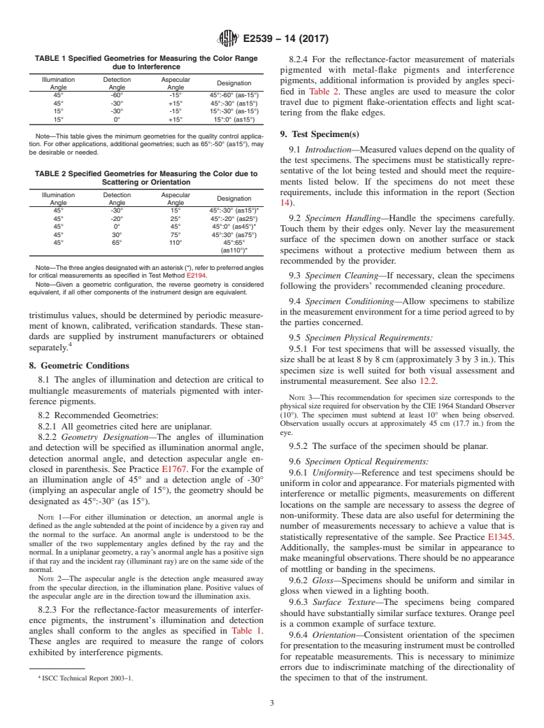
SCOPE
1.1 This test method covers the instrumental requirements and required parameters needed to make instrumental color measurements of thin film interference pigments. This test method is designed to encompass interference pigments used in architectural applications, automobiles, coatings, cosmetics, inks, packaging, paints, plastics, printing, security, and other applications.
1.2 Characterization of the optical behavior of materials colored with interference pigments requires measurement at multiple angles of illumination and detection.
1.3 Data taken utilizing this test method are quantitative and are appropriate for quality control of interference pigment color.
1.4 The measurement results are usually expressed as reflectance factors, tristimulus color values, or as CIE L*a*b* color coordinates and color difference.
1.5 The totality of data taken may not be necessary for evaluating mixtures also containing non-interference pigments. The committee is investigating and evaluating the appropriateness of this test method for those materials. It is the responsibility of the users to determine the applicability of this test method for their specific applications.
1.6 Interference pigments are typically evaluated for color and color appearance in a medium, such as paint or ink. The gonioapparent effect depends strongly on the physical and chemical properties of the medium. Some of the properties affecting color and color appearance include vehicle viscosity, thickness, transparency, and volume solids. As a general rule, for quality control purposes, interference pigments are best evaluated in a masstone product form. In some cases this product form may be the final product form, or more typically a qualified simulation of the intended product form (such as a paint drawdown) that in terms of color and appearance correlates to final product application.
1.7 This standard does not address the requirements for characterizing materials containing metal flake pigments. Measurements of the optical characteristics of materials containing metal flake pigments are described in Test Method E2194.
1.8 The values stated in SI units are to be regarded as the standard. The values given in parentheses are for information only.
1.9 This standard does not purport to address all of the safety concerns, if any, associated with its use. It is the responsibility of the user of this standard to establish appropriate safety and health practices and determine the applicability of regulatory limitations prior to use.
1.10 This international standard was developed in accordance with internationally recognized principles on standardization established in the Decision on Principles for the Development of International Standards, Guides and Recommendations issued by the World Trade Organization Technical Barriers to Trade (TBT) Committee.
General Information
Buy Standard
Standards Content (Sample)
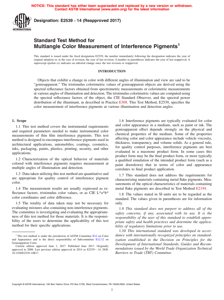
NOTICE: This standard has either been superseded and replaced by a new version or withdrawn.
Contact ASTM International (www.astm.org) for the latest information
Designation: E2539 − 14 (Reapproved 2017)
Standard Test Method for
Multiangle Color Measurement of Interference Pigments
This standard is issued under the fixed designation E2539; the number immediately following the designation indicates the year of
original adoption or, in the case of revision, the year of last revision.Anumber in parentheses indicates the year of last reapproval.A
superscript epsilon (´) indicates an editorial change since the last revision or reapproval.
INTRODUCTION
Objects that exhibit a change in color with different angles of illumination and view are said to be
“gonioapparent.” The tristimulus colorimetric values of gonioapparent objects are derived using the
spectral reflectance factors obtained from spectrometric measurements or colorimetric measurements
atvariousanglesofilluminationanddetection.Thetristimuluscolorimetricvaluesarecomputedusing
the spectral reflectance factors of the object, the CIE Standard Observer, and the spectral power
distribution of the illuminant, as described in Practice E308. This Test Method, E2539, specifies the
color measurement of interference pigments at various illumination and detection angles.
1. Scope 1.6 Interference pigments are typically evaluated for color
and color appearance in a medium, such as paint or ink. The
1.1 This test method covers the instrumental requirements
gonioapparent effect depends strongly on the physical and
and required parameters needed to make instrumental color
chemical properties of the medium. Some of the properties
measurements of thin film interference pigments. This test
affecting color and color appearance include vehicle viscosity,
methodisdesignedtoencompassinterferencepigmentsusedin
thickness, transparency, and volume solids. As a general rule,
architectural applications, automobiles, coatings, cosmetics,
for quality control purposes, interference pigments are best
inks, packaging, paints, plastics, printing, security, and other
evaluated in a masstone product form. In some cases this
applications.
product form may be the final product form, or more typically
1.2 Characterization of the optical behavior of materials
a qualified simulation of the intended product form (such as a
colored with interference pigments requires measurement at
paint drawdown) that in terms of color and appearance
multiple angles of illumination and detection.
correlates to final product application.
1.3 Datatakenutilizingthistestmethodarequantitativeand
1.7 This standard does not address the requirements for
are appropriate for quality control of interference pigment
characterizingmaterialscontainingmetalflakepigments.Mea-
color.
surements of the optical characteristics of materials containing
metal flake pigments are described in Test Method E2194.
1.4 The measurement results are usually expressed as re-
flectance factors, tristimulus color values, or as CIE L*a*b*
1.8 The values stated in SI units are to be regarded as the
color coordinates and color difference.
standard. The values given in parentheses are for information
1.5 The totality of data taken may not be necessary for only.
evaluatingmixturesalsocontainingnon-interferencepigments.
1.9 This standard does not purport to address all of the
The committee is investigating and evaluating the appropriate-
safety concerns, if any, associated with its use. It is the
ness of this test method for those materials. It is the responsi-
responsibility of the user of this standard to establish appro-
bility of the users to determine the applicability of this test
priate safety and health practices and determine the applica-
method for their specific applications.
bility of regulatory limitations prior to use.
1.10 This international standard was developed in accor-
dance with internationally recognized principles on standard-
This test method is under the jurisdiction of ASTM Committee E12 on Color
and Appearance and is the direct responsibility of Subcommittee E12.12 on
ization established in the Decision on Principles for the
Gonioapparent Color.
Development of International Standards, Guides and Recom-
Current edition approved June 1, 2017. Published June 2017. Originally
mendations issued by the World Trade Organization Technical
approved in 2008. Last previous edition approved in 2014 as E2539– 14. DOI:
10.1520/E2539-14R17. Barriers to Trade (TBT) Committee.
Copyright © ASTM International, 100 Barr Harbor Drive, PO Box C700, West Conshohocken, PA 19428-2959. United States
E2539 − 14 (2017)
2. Referenced Documents 5.2 These data can be used for acceptance testing, design
2 purposes, research, manufacturing control, and quality control.
2.1 ASTM Standards:
E284Terminology of Appearance
5.3 Specimensmustbestatisticallyrepresentativeoftheend
E308PracticeforComputingtheColorsofObjectsbyUsing
use.
the CIE System
5.4 Applicability of this test method for other materials,
E805Practice for Identification of Instrumental Methods of
includingcombininginterferencepigmentswithabsorbingand
Color or Color-Difference Measurement of Materials
scattering pigments should be confirmed by the user.
E1164PracticeforObtainingSpectrometricDataforObject-
Color Evaluation
6. Environmental Conditions
E1345Practice for Reducing the Effect of Variability of
Color Measurement by Use of Multiple Measurements
6.1 If the standard laboratory conditions listed below
E1708Practice for Electronic Interchange of Color and
change during the test or from test to test by an appreciable
Appearance Data
amount,theseconditionsmayreduceaccuracyandprecisionof
E1767Practice for Specifying the Geometries of Observa-
this test method. In some cases these effects may only be
tion and Measurement to Characterize the Appearance of
observed during the performance of the test.
Materials
6.2 Factors affecting test results—The following factors are
E2194Test Method for Multiangle Color Measurement of
known to affect the test results.
Metal Flake Pigmented Materials
6.2.1 Extraneous radiation—light from sources other than
E2480Practice for Conducting an Interlaboratory Study to
theilluminator(s)andanynear-infrared(NIR)mustbeshielded
Determine the Precision of a Test Method with Multi-
from entering the test apparatus.
Valued Measurands
6.2.2 Vibrations—mechanical oscillations that cause com-
2.2 ISCC Publications:
ponents of the apparatus to move relative to one another may
Technical Report 2003–1Guide to Material Standards and
cause errors in test results.
Their Use in Color Measurement
6.2.3 Thermal changes—temperature changes occurring
3. Terminology
during a test or differences in temperature between testing
locations may affect calibration.
3.1 Terms and definitions in Terminology E284, and Prac-
6.2.4 Power input fluctuations—large changes in the line
tice E1767 and Test Method E2194 are applicable to this test
frequency or supply voltage may cause the apparatus to report
method. See Section 5 of E284 for “Specialized Terminology
erroneous results.
on Gonioapparent Phenomena.”
6.3 Standardization—The system must allow for successful
4. Summary of Test Method
standardization. If the system cannot be standardized, consult
4.1 This test method describes the instrumental geometries,
the manufacturer’s user guide.
including abridged goniospectrometry, used to measure inter-
6.4 Controlling factors—Accuracy and precision can be
ference pigments. Optical characterization requires color mea-
enhanced by controlling and regulating each factor within the
surementatmultipleilluminationandmultipledetectionangles
constraintsoftheallowableexperimentalerror.Thevaluesand
specified in this procedure. These sets of illumination and
limitsforthesefactorsaretypicallydeterminedexperimentally
detection angles are specified in the test method. Standardiza-
by the user.
tion and verification of the instrument used to measure these
materials are defined. The requirements for selection of speci-
7. Apparatus
mens and measurement procedures are provided. The results
are reported in terms of reflectance factors, CIE tristimulus
7.1 Multiangle Spectrometer—Thistestmethodspecifiesthe
values,andothercolorcoordinatesystemsthatdefinethecolor
required illumination and detection angles of multiangle spec-
of the object. Expected values of precision are presented.
trometers. These multiangle spectrometers are designed spe-
cifically to characterize the optical behavior of materials
5. Significance and Use
coloredwithinterferencepigments.Geometriesarespecifiedin
Section8.Thespectrometermayeitherbeagoniospectrometer
5.1 This test method is designed to provide color data
obtained from spectral reflectance factors at specific illumina- or an abridged goniospectrometer.
tion and detection angles for interference pigments. Informa-
7.1.1 Bi-directional spectrometers or colorimeters with a
tion presented in this test method is based upon data taken on
single angle of measurement; such as 45°:0° or 0°:45°, and
materials exclusively pigmented with interference pigments.
spectrometers using hemispherical geometry cannot ad-
equately characterize the gonioapparency of these materials.
7.1.2 Multiangle spectrometers or colorimeters similar to
For referenced ASTM standards, visit the ASTM website, www.astm.org, or
those specified in Test Method E2194 cannot adequately
contact ASTM Customer Service at service@astm.org. For Annual Book of ASTM
characterize the gonioapparency of these materials.
Standards volume information, refer to the standard’s Document Summary page on
the ASTM website.
7.2 System Validation Materials—The precision and bias of
Available from the Inter-Society Color Council, 1191 Sunset Hills Road,
Reston, VA 20190, www.iscc.org. the entire measurement system, including calculation of CIE
E2539 − 14 (2017)
TABLE 1 Specified Geometries for Measuring the Color Range
8.2.4 For the reflectance-factor measurement of materials
due to Interference
pigmented with metal-flake pigments and interference
Illumination Detection Aspecular
pigments, additional information is provided by angles speci-
Designation
Angle Angle Angle
fied in Table 2. These angles are used to measure the color
45° -60° -15° 45°:-60° (as-15°)
travel due to pigment flake-orientation effects and light scat-
45° -30° +15° 45°:-30° (as15°)
15° -30° -15° 15°:-30° (as-15°)
tering from the flake edges.
15° 0° +15° 15°:0° (as15°)
9. Test Specimen(s)
Note—This table gives the minimum geometries for the quality control applica-
tion. For other applications, additional geometries; such as 65°:-50° (as15°), may
9.1 Introduction—Measuredvaluesdependonthequalityof
be desirable or needed.
the test specimens. The specimens must be statistically repre-
sentative of the lot being tested and should meet the require-
TABLE 2 Specified Geometries for Measuring the Color due to
Scattering or Orientation ments listed below. If the specimens do not meet these
requirements, include this information in the report (Section
Illumination Detection Aspecular
Designation
Angle Angle Angle
14).
45° -30° 15° 45°:-30° (as15°)*
45° -20° 25° 45°:-20° (as25°) 9.2 Specimen Handling—Handle the specimens carefully.
45° 0° 45° 45°:0° (as45°)*
Touch them by their edges only. Never lay the measurement
45° 30° 75° 45°:30° (as75°)
surface of the specimen down on another surface or stack
45° 65° 110° 45°:65°
(as110°)* specimens without a protective medium between them as
recommended by the provider.
Note—The three angles designated with an asterisk (*), refer to preferred angles
for critical measurements as specified in Test Method E2194.
9.3 Specimen Cleaning—If necessary, clean the specimens
Note—Given a geometric configuration, the reverse geometry is considered
following the providers’ recommended cleaning procedure.
equivalent, if all other components of the instrument design are equivalent.
9.4 Specimen Conditioning—Allow specimens to stabilize
inthemeasurementenvironmentforatimeperiodagreedtoby
tristimulus values, should be determined by periodic measure-
the parties concerned.
ment of known, calibrated, verification standards. These stan-
dards are supplied by instrument manufacturers or obtained
9.5 Specimen Physical Requirements:
separately.
9.5.1 For test specimens that will be assessed visually, the
sizeshallbeatleast8by8cm(approximately3by3in.).This
8. Geometric Conditions
specimen size is well suited for both visual assessment and
8.1 The angles of illumination and detection are critical to
instrumental measurement. See also 12.2.
multiangle measurements of materials pigmented with inter-
NOTE 3—This recommendation for specimen size corresponds to the
ference pigments.
physicalsizerequiredforobservationbytheCIE1964StandardObserver
(10°). The specimen must subtend at least 10° when being observed.
8.2 Recommended Geometries:
Observation usually occurs at approximately 45 cm (17.7 in.) from the
8.2.1 All geometries cited here are uniplanar.
eye.
8.2.2 Geometry Designation—The angles of illumination
9.5.2 The surface of the specimen should be planar.
and detection will be specified as illumination anormal angle,
detection anormal angle, and detection aspecular angle en-
9.6 Specimen Optical Requirements:
closed in parenthesis. See Practice E1767. For the example of
9.6.1 Uniformity—Reference and test specimens should be
an illumination angle of 45° and a detection angle of -30°
uniformincolorandappearance.Formaterialspigmentedwith
(implying an aspecular angle of 15°), the geometry should be
interference or metallic pigments, measurements on different
designated as 45°:-30° (as 15°).
locations on the sample are necessary to assess the degree of
non-uniformity. These data are also useful for determining the
NOTE 1—For either illumination or detection, an anormal angle is
definedastheanglesubtendedatthepointofincidencebyagivenrayand number of measurements necessary to achieve a value that is
the normal to the surface. An anormal angle is understood to be the
statistically representative of the sample. See Practice E1345.
smaller of the two supplementary angles defined by the ray and the
Additionally, the samples-must be similar in appearance to
normal. In a uniplanar geometry, a ray’s anormal angle has a positive sign
makemeaningfulobservations.Thereshouldbenoappearance
if that ray and the incident ray (illuminant ray) are on the same side of the
of mottling or banding in the specimens.
normal.
NOTE 2—The aspecular angle is the detection angle measured away
9.6.2 Gloss—Specimens should be uniform and similar in
from the specular direction, in the illumination plane. Positive values of
gloss when viewed in a lighting booth.
the aspecular angle are in the direction toward the illumination axis.
9.6.3 Surface Texture—The specimens being compared
8.2.3 For the reflectance-factor measurements of int
...
This document is not an ASTM standard and is intended only to provide the user of an ASTM standard an indication of what changes have been made to the previous version. Because
it may not be technically possible to adequately depict all changes accurately, ASTM recommends that users consult prior editions as appropriate. In all cases only the current version
of the standard as published by ASTM is to be considered the official document.
Designation: E2539 − 14 E2539 − 14 (Reapproved 2017)
Standard Test Method for
Multiangle Color Measurement of Interference Pigments
This standard is issued under the fixed designation E2539; the number immediately following the designation indicates the year of
original adoption or, in the case of revision, the year of last revision. A number in parentheses indicates the year of last reapproval. A
superscript epsilon (´) indicates an editorial change since the last revision or reapproval.
INTRODUCTION
Objects that exhibit a change in color with different angles of illumination and view are said to be
“gonioapparent.” The tristimulus colorimetric values of gonioapparent objects are derived using the
spectral reflectance factors obtained from spectrometric measurements or colorimetric measurements
at various angles of illumination and detection. The tristimulus colorimetric values are computed using
the spectral reflectance factors of the object, the CIE Standard Observer, and the spectral power
distribution of the illuminant, as described in Practice E308. This Test Method, E2539, specifies the
color measurement of interference pigments at various illumination and detection angles.
1. Scope
1.1 This test method covers the instrumental requirements and required parameters needed to make instrumental color
measurements of thin film interference pigments. This test method is designed to encompass interference pigments used in
architectural applications, automobiles, coatings, cosmetics, inks, packaging, paints, plastics, printing, security, and other
applications.
1.2 Characterization of the optical behavior of materials colored with interference pigments requires measurement at multiple
angles of illumination and detection.
1.3 Data taken utilizing this test method are quantitative and are appropriate for quality control of interference pigment color.
1.4 The measurement results are usually expressed as reflectance factors, tristimulus color values, or as CIE L*a*b* color
coordinates and color difference.
1.5 The totality of data taken may not be necessary for evaluating mixtures also containing non-interference pigments. The
committee is investigating and evaluating the appropriateness of this test method for those materials. It is the responsibility of the
users to determine the applicability of this test method for their specific applications.
1.6 Interference pigments are typically evaluated for color and color appearance in a medium, such as paint or ink. The
gonioapparent effect depends strongly on the physical and chemical properties of the medium. Some of the properties affecting
color and color appearance include vehicle viscosity, thickness, transparency, and volume solids. As a general rule, for quality
control purposes, interference pigments are best evaluated in a masstone product form. In some cases this product form may be
the final product form, or more typically a qualified simulation of the intended product form (such as a paint drawdown) that in
terms of color and appearance correlates to final product application.
1.7 This standard does not address the requirements for characterizing materials containing metal flake pigments. Measurements
of the optical characteristics of materials containing metal flake pigments are described in Test Method E2194.
1.8 The values stated in SI units are to be regarded as the standard. The values given in parentheses are for information only.
1.9 This standard does not purport to address all of the safety concerns, if any, associated with its use. It is the responsibility
of the user of this standard to establish appropriate safety and health practices and determine the applicability of regulatory
limitations prior to use.
1.10 This international standard was developed in accordance with internationally recognized principles on standardization
established in the Decision on Principles for the Development of International Standards, Guides and Recommendations issued
by the World Trade Organization Technical Barriers to Trade (TBT) Committee.
This test method is under the jurisdiction of ASTM Committee E12 on Color and Appearance and is the direct responsibility of Subcommittee E12.12 on Gonioapparent
Color.
Current edition approved Nov. 1, 2014June 1, 2017. Published November 2014June 2017. Originally approved in 2008. Last previous edition approved in 20122014 as
E2539 – 12.14. DOI: 10.1520/E2539-14.10.1520/E2539-14R17.
Copyright © ASTM International, 100 Barr Harbor Drive, PO Box C700, West Conshohocken, PA 19428-2959. United States
E2539 − 14 (2017)
2. Referenced Documents
2.1 ASTM Standards:
E284 Terminology of Appearance
E308 Practice for Computing the Colors of Objects by Using the CIE System
E805 Practice for Identification of Instrumental Methods of Color or Color-Difference Measurement of Materials
E1164 Practice for Obtaining Spectrometric Data for Object-Color Evaluation
E1345 Practice for Reducing the Effect of Variability of Color Measurement by Use of Multiple Measurements
E1708 Practice for Electronic Interchange of Color and Appearance Data
E1767 Practice for Specifying the Geometries of Observation and Measurement to Characterize the Appearance of Materials
E2194 Test Method for Multiangle Color Measurement of Metal Flake Pigmented Materials
E2480 Practice for Conducting an Interlaboratory Study to Determine the Precision of a Test Method with Multi-Valued
Measurands
2.2 ISCC Publications:
Technical Report 2003–1 Guide to Material Standards and Their Use in Color Measurement
3. Terminology
3.1 Terms and definitions in Terminology E284, and Practice E1767 and Test Method E2194 are applicable to this test method.
See Section 5 of E284 for “Specialized Terminology on Gonioapparent Phenomena.”
4. Summary of Test Method
4.1 This test method describes the instrumental geometries, including abridged goniospectrometry, used to measure interference
pigments. Optical characterization requires color measurement at multiple illumination and multiple detection angles specified in
this procedure. These sets of illumination and detection angles are specified in the test method. Standardization and verification
of the instrument used to measure these materials are defined. The requirements for selection of specimens and measurement
procedures are provided. The results are reported in terms of reflectance factors, CIE tristimulus values, and other color coordinate
systems that define the color of the object. Expected values of precision are presented.
5. Significance and Use
5.1 This test method is designed to provide color data obtained from spectral reflectance factors at specific illumination and
detection angles for interference pigments. Information presented in this test method is based upon data taken on materials
exclusively pigmented with interference pigments.
5.2 These data can be used for acceptance testing, design purposes, research, manufacturing control, and quality control.
5.3 Specimens must be statistically representative of the end use.
5.4 Applicability of this test method for other materials, including combining interference pigments with absorbing and
scattering pigments should be confirmed by the user.
6. Environmental Conditions
6.1 If the standard laboratory conditions listed below change during the test or from test to test by an appreciable amount, these
conditions may reduce accuracy and precision of this test method. In some cases these effects may only be observed during the
performance of the test.
6.2 Factors affecting test results—The following factors are known to affect the test results.
6.2.1 Extraneous radiation—light from sources other than the illuminator(s) and any near-infrared (NIR) must be shielded from
entering the test apparatus.
6.2.2 Vibrations—mechanical oscillations that cause components of the apparatus to move relative to one another may cause
errors in test results.
6.2.3 Thermal changes—temperature changes occurring during a test or differences in temperature between testing locations
may affect calibration.
6.2.4 Power input fluctuations—large changes in the line frequency or supply voltage may cause the apparatus to report
erroneous results.
6.3 Standardization—The system must allow for successful standardization. If the system cannot be standardized, consult the
manufacturer’s user guide.
For referenced ASTM standards, visit the ASTM website, www.astm.org, or contact ASTM Customer Service at service@astm.org. For Annual Book of ASTM Standards
volume information, refer to the standard’s Document Summary page on the ASTM website.
Available from the Inter-Society Color Council, 1191 Sunset Hills Road, Reston, VA 20190, www.iscc.org.
E2539 − 14 (2017)
6.4 Controlling factors—Accuracy and precision can be enhanced by controlling and regulating each factor within the
constraints of the allowable experimental error. The values and limits for these factors are typically determined experimentally by
the user.
7. Apparatus
7.1 Multiangle Spectrometer—This test method specifies the required illumination and detection angles of multiangle
spectrometers. These multiangle spectrometers are designed specifically to characterize the optical behavior of materials colored
with interference pigments. Geometries are specified in Section 8. The spectrometer may either be a goniospectrometer or an
abridged goniospectrometer.
7.1.1 Bi-directional spectrometers or colorimeters with a single angle of measurement; such as 45°:0° or 0°:45°, and
spectrometers using hemispherical geometry cannot adequately characterize the gonioapparency of these materials.
7.1.2 Multiangle spectrometers or colorimeters similar to those specified in Test Method E2194 cannot adequately characterize
the gonioapparency of these materials.
7.2 System Validation Materials—The precision and bias of the entire measurement system, including calculation of CIE
tristimulus values, should be determined by periodic measurement of known, calibrated, verification standards. These standards are
supplied by instrument manufacturers or obtained separately.
8. Geometric Conditions
8.1 The angles of illumination and detection are critical to multiangle measurements of materials pigmented with interference
pigments.
8.2 Recommended Geometries:
8.2.1 All geometries cited here are uniplanar.
8.2.2 Geometry Designation—The angles of illumination and detection will be specified as illumination anormal angle,
detection anormal angle, and detection aspecular angle enclosed in parenthesis. See Practice E1767. For the example of an
illumination angle of 45° and a detection angle of -30° (implying an aspecular angle of 15°), the geometry should be designated
as 45°:-30° (as 15°).
NOTE 1—For either illumination or detection, an anormal angle is defined as the angle subtended at the point of incidence by a given ray and the normal
to the surface. An anormal angle is understood to be the smaller of the two supplementary angles defined by the ray and the normal. In a uniplanar
geometry, a ray’s anormal angle has a positive sign if that ray and the incident ray (illuminant ray) are on the same side of the normal.
NOTE 2—The aspecular angle is the detection angle measured away from the specular direction, in the illumination plane. Positive values of the
aspecular angle are in the direction toward the illumination axis.
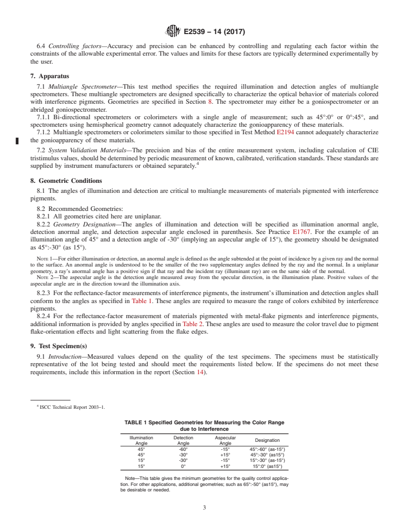
8.2.3 For the reflectance-factor measurements of interference pigments, the instrument’s illumination and detection angles shall
conform to the angles as specified in Table 1. These angles are required to measure the range of colors exhibited by interference
pigments.
8.2.4 For the reflectance-factor measurement of materials pigmented with metal-flake pigments and interference pigments,
additional information is provided by angles specified in Table 2. These angles are used to measure the color travel due to pigment
flake-orientation effects and light scattering from the flake edges.
9. Test Specimen(s)
9.1 Introduction—Measured values depend on the quality of the test specimens. The specimens must be statistically
representative of the lot being tested and should meet the requirements listed below. If the specimens do not meet these
requirements, include this information in the report (Section 14).
ISCC Technical Report 2003–1.
TABLE 1 Specified Geometries for Measuring the Color Range
due to Interference
Illumination Detection Aspecular
Designation
Angle Angle Angle
45° -60° -15° 45°:-60° (as-15°)
45° -30° +15° 45°:-30° (as15°)
15° -30° -15° 15°:-30° (as-15°)
15° 0° +15° 15°:0° (as15°)
Note—This table gives the minimum geometries for the quality control applica-
tion. For other applications, additional geometries; such as 65°:-50° (as15°), may
be desirable or needed.
E2539 − 14 (2017)
TABLE 2 Specified Geometries for Measuring the Color due to
Scattering or Orientation
Illumination Detection Aspecular
Designation
Angle Angle Angle
45° -30° 15° 45°:-30° (as15°)*
45° -20° 25° 45°:-20° (as25°)
45° 0° 45° 45°:0° (as45°)*
45° 30° 75° 45°:30° (as75°)
45° 65° 110° 45°:65°
(as110°)*
Note—The three angles designated with an asterisk (*), refer to preferred angles
for critical measurements as specified in Test Method E2194.
Note—Given a geometric configuration, the reverse geometry is considered
equivalent, if all other components of the instrument design are equivalent.
9.2 Specimen Handling—Handle the specimens carefully. Touch them by their edges only. Never lay the measurement surface
of the specimen down on another surface or stack specimens without a protective medium between them as recommended by the
provider.
9.3 Specimen Cleaning—If necessary, clean the specimens following the providers’ recommended cleaning procedure.
9.4 Specimen Conditioning—Allow specimens to stabilize in the measurement environment for a time period agreed to by the
parties concerned.
9.5 Specimen Physical Requirements:
9.5.1 For test specimens that will be assessed visually, the size shall be at least 8 by 8 cm (approximately 3 by 3 in.). This
specimen size is well suited for both visual assessment and instrumental measurement. See also 12.2.
NOTE 3—This recommendation for specimen size corresponds to the physical size required for observation by the CIE 1964 Standard Observer (10°).
The specimen must subtend at least 10° when being observed. Observation usually occurs at approximately 45 cm (17.7 in.) from the eye.
...
Questions, Comments and Discussion
Ask us and Technical Secretary will try to provide an answer. You can facilitate discussion about the standard in here.