


ASTM G39-99(2016)
(Practice)Standard Practice for Preparation and Use of Bent-Beam Stress-Corrosion Test Specimens
Standard Practice for Preparation and Use of Bent-Beam Stress-Corrosion Test Specimens
SIGNIFICANCE AND USE
5.1 The bent-beam specimen is designed for determining the stress-corrosion behavior of alloy sheets and plates in a variety of environments. The bent-beam specimens are designed for testing at stress levels below the elastic limit of the alloy. For testing in the plastic range, U-bend specimens should be employed (see Practice G30). Although it is possible to stress bent-beam specimens into the plastic range, the stress level cannot be calculated for plastically-stressed three- and four-point loaded specimens as well as the double-beam specimens. Therefore, the use of bent-beam specimens in the plastic range is not recommended for general use.
SCOPE
1.1 This practice covers procedures for designing, preparing, and using bent-beam stress-corrosion specimens.
1.2 Different specimen configurations are given for use with different product forms, such as sheet or plate. This practice is applicable to specimens of any metal that are stressed to levels less than the elastic limit of the material, and therefore, the applied stress can be accurately calculated or measured (see Note 1). Stress calculations by this practice are not applicable to plastically stressed specimens.
Note 1: It is the nature of these practices that only the applied stress can be calculated. Since stress-corrosion cracking is a function of the total stress, for critical applications and proper interpretation of results, the residual stress (before applying external stress) or the total elastic stress (after applying external stress) should be determined by appropriate nondestructive methods, such as X-ray diffraction (1).2
1.3 Test procedures are given for stress-corrosion testing by exposure to gaseous and liquid environments.
1.4 The bent-beam test is best suited for flat product forms, such as sheet, strip, and plate. For plate material the bent-beam specimen is more difficult to use because more rugged specimen holders must be built to accommodate the specimens. A double-beam modification of a four-point loaded specimen to utilize heavier materials is described in 10.5.
1.5 The exposure of specimens in a corrosive environment is treated only briefly since other practices deal with this aspect, for example, Specification D1141, and Practices G30, G36, G44, G50, and G85. The experimenter is referred to ASTM Special Technical Publication 425 (2).
1.6 The bent-beam practice generally constitutes a constant strain (deflection) test. Once cracking has initiated, the state of stress at the tip of the crack as well as in uncracked areas has changed, and therefore, the known or calculated stress or strain values discussed in this practice apply only to the state of stress existing before initiation of cracks.
1.7 The values stated in SI units are to be regarded as standard. The inch-pound values in parentheses are provided for information.
1.8 This standard does not purport to address all of the safety concerns, if any, associated with its use. It is the responsibility of the user of this standard to establish appropriate safety and health practices and determine the applicability of regulatory limitations prior to use. (For more specific safety hazard information see Section 7 and 12.1.)
General Information
Buy Standard
Standards Content (Sample)
NOTICE: This standard has either been superseded and replaced by a new version or withdrawn.
Contact ASTM International (www.astm.org) for the latest information
Designation:G39 −99 (Reapproved 2016)
Standard Practice for
Preparation and Use of Bent-Beam Stress-Corrosion Test
Specimens
ThisstandardisissuedunderthefixeddesignationG39;thenumberimmediatelyfollowingthedesignationindicatestheyearoforiginal
adoptionor,inthecaseofrevision,theyearoflastrevision.Anumberinparenthesesindicatestheyearoflastreapproval.Asuperscript
epsilon (´) indicates an editorial change since the last revision or reapproval.
1. Scope valuesdiscussedinthispracticeapplyonlytothestateofstress
existing before initiation of cracks.
1.1 This practice covers procedures for designing,
preparing, and using bent-beam stress-corrosion specimens. 1.7 The values stated in SI units are to be regarded as
standard. The inch-pound values in parentheses are provided
1.2 Differentspecimenconfigurationsaregivenforusewith
for information.
different product forms, such as sheet or plate. This practice is
1.8 This standard does not purport to address all of the
applicable to specimens of any metal that are stressed to levels
safety concerns, if any, associated with its use. It is the
less than the elastic limit of the material, and therefore, the
responsibility of the user of this standard to establish appro-
applied stress can be accurately calculated or measured (see
priate safety and health practices and determine the applica-
Note 1). Stress calculations by this practice are not applicable
bility of regulatory limitations prior to use. (For more specific
to plastically stressed specimens.
safety hazard information see Section 7 and 12.1.)
NOTE 1—It is the nature of these practices that only the applied stress
canbecalculated.Sincestress-corrosioncrackingisafunctionofthetotal
2. Referenced Documents
stress, for critical applications and proper interpretation of results, the
residual stress (before applying external stress) or the total elastic stress
2.1 ASTM Standards:
(after applying external stress) should be determined by appropriate
D1141Practice for the Preparation of Substitute Ocean
nondestructive methods, such as X-ray diffraction (1).
Water
1.3 Test procedures are given for stress-corrosion testing by
G30 Practice for Making and Using U-Bend Stress-
exposure to gaseous and liquid environments.
Corrosion Test Specimens
G36Practice for Evaluating Stress-Corrosion-Cracking Re-
1.4 The bent-beam test is best suited for flat product forms,
sistance of Metals and Alloys in a Boiling Magnesium
suchassheet,strip,andplate.Forplatematerialthebent-beam
specimen is more difficult to use because more rugged speci- Chloride Solution
G44PracticeforExposureofMetalsandAlloysbyAlternate
men holders must be built to accommodate the specimens. A
double-beam modification of a four-point loaded specimen to Immersion in Neutral 3.5 % Sodium Chloride Solution
G50Practice for Conducting Atmospheric Corrosion Tests
utilize heavier materials is described in 10.5.
on Metals
1.5 The exposure of specimens in a corrosive environment
G85Practice for Modified Salt Spray (Fog) Testing
is treated only briefly since other practices deal with this
2.2 NACE Documents:
aspect, for example, Specification D1141, and Practices G30,
NACE TM0177-96Laboratory Testing of Metals for Resis-
G36, G44, G50, and G85. The experimenter is referred to
tancetoSpecificFormsofEnvironmentalCrackinginH S
ASTM Special Technical Publication 425 (2). 2
Environments
1.6 The bent-beam practice generally constitutes a constant
strain (deflection) test. Once cracking has initiated, the state of
3. Terminology
stress at the tip of the crack as well as in uncracked areas has
3.1 Definitions of Terms Specific to This Standard:
changed,andtherefore,theknownorcalculatedstressorstrain
3.1.1 cracking time—the time elapsed from the inception of
test until the appearance of cracking.
This practice is under the jurisdiction ofASTM Committee G01 on Corrosion
of Metals and is the direct responsibility of Subcommittee G01.06 on Environmen-
tally Assisted Cracking. For referenced ASTM standards, visit the ASTM website, www.astm.org, or
Current edition approved May 1, 2016. Published May 2016. Originally contact ASTM Customer Service at service@astm.org. For Annual Book of ASTM
approvedin1973.Lastpreviouseditionapprovedin2011asG39–99(2011).DOI: Standards volume information, refer to the standard’s Document Summary page on
10.1520/G0039-99R16. the ASTM website.
2 4
The boldface numbers in parentheses refer to a list of references at the end of Available from NACE International (NACE), 1440 South Creek Dr., Houston,
this standard. TX 77084-4906, http://www.nace.org.
Copyright © ASTM International, 100 Barr Harbor Drive, PO Box C700, West Conshohocken, PA 19428-2959. United States
G39−99 (2016)
3.1.1.1 Discussion—The test begins when the stress is
applied and the stressed specimen is exposed to the corrosive
environment, whichever occurs later.
3.1.1.2 Discussion—The specimen is considered to have
failed when cracks are detected. Presence of cracks can be
determined with or without optical, mechanical, or electronic
aids. However, for meaningful interpretation, comparisons
should be made only among tests employing crack detection
methods of equivalent sensitivity.
3.1.2 stress-corrosion cracking—a cracking process requir-
ingthesimultaneousactionofacorrodentandsustainedtensile
stress. This excludes corrosion-reduced sections that fail by
fastfracture.Italsoexcludesintercrystallineortranscrystalline
corrosion which can disintegrate an alloy without either
applied or residual stress.
4. Summary of Practice
4.1 This practice involves the quantitative stressing of a
beamspecimenbyapplication of a bending stress.Theapplied
stress is determined from the size of the specimen and the
bendingdeflection.Thestressedspecimensthenareexposedto
the test environment and the time required for cracks to
developisdetermined.Thiscrackingtimeisusedasameasure
of the stress-corrosion resistance of the material in the test
environment at the stress level utilized.
5. Significance and Use
5.1 The bent-beam specimen is designed for determining
the stress-corrosion behavior of alloy sheets and plates in a
variety of environments. The bent-beam specimens are de-
FIG. 1 Schematic Specimen and Holder Configurations
signed for testing at stress levels below the elastic limit of the
alloy.Fortestingintheplasticrange,U-bendspecimensshould
be employed (see Practice G30). Although it is possible to
6.1.2 Whenthestress-corrosiontestisconductedbyimmer-
stress bent-beam specimens into the plastic range, the stress
sion in an electrolyte, galvanic action between specimen and
level cannot be calculated for plastically-stressed three- and
holder (or spacer) shall be prevented (see Note 5). This is
four-point loaded specimens as well as the double-beam
accomplishedby(1)makingtheholderofthesamematerialas
specimens. Therefore, the use of bent-beam specimens in the
the individual specimens, (2) inserting electrically insulating
plastic range is not recommended for general use.
materials between specimen and holder at all points of contact
(see Note 4), (3) making the entire holder out of a nonmetallic
6. Apparatus
material (see Note 4), or (4) coating the holder with an
6.1 Specimen Holders—Bent-beam specimens require a
electrically nonconducting coating that effectively prevents
specimen holder for each specimen, designed to retain the
contact between holder and electrolyte.
applied stress on the specimen. Typical specimen holder
6.1.3 Crevice corrosion may occur in an electrolyte at
configurations are shown schematically in Fig. 1.
contact points between specimen and holder (or spacer). In
these instances the critical areas should be packed with a
NOTE 2—The double-beam specimen, more fully described in 10.5,is
hydrophobic filler (such as grease or wax).
self-contained and does not require a holder.
NOTE 3—Specimen holders can be modified from the constant defor-
NOTE 5—In atmospheres (gas) galvanic action between specimen and
mation type shown in Fig. 1 to give a constant-load type of stressing. For
holder either does not exist or is confined to a very small area as
instance, the loading bolt can be supplanted by a spring or deadweight
experienced in outdoor exposure tests.
arrangement to change the mode of loading.
6.2 StressingJigs—Three-pointandfour-pointloadedspeci-
6.1.1 The holder shall be made of a material that would
men holders, Fig. 1(b and c), contain a stressing feature in the
withstand the influence of the environment without deteriora-
form of a loading screw.To stress two-point loaded specimens
tion or change in shape.
(Fig. 1(a)), a separate stressing jig shall be used.Aconvenient
NOTE4—Itshouldberecognizedthatmanyplasticstendtocreepwhen
stressing jig is shown in Fig. 2.
subjectedtosustainedloads.Ifspecimenholdersorinsulatorsaremadeof
suchmaterials,theappliedstressonthespecimenmaychangeappreciably NOTE 6—The double-beam specimen, described in 10.5, requires a
with time. By proper choice of holder and insulator materials, however, mechanical or hydraulic stressing frame (a universal tension testing
many plastics can be used, especially in short-time tests. machine can also be used) as well as welding equipment.
G39−99 (2016)
8. Sampling
8.1 Test specimens shall be selected so that they represent
the material to be tested. In simulating a service condition, the
directionofloadapplicationinthespecimenshallrepresentthe
anticipatedloadingdirectioninservicewithrespecttoprocess-
ing conditions, for example, rolling direction.
8.2 Paragraphs 9.4 and 9.5 deal specifically with specimen
selection as related to the original material surface.
9. Test Specimen
9.1 The bent-beam, stress-corrosion specimens shall be flat
strips of metal of uniform, rectangular cross section, and
uniform thickness.
9.2 The identification of individual specimens should be
permanentlyinscribedateachendofthespecimenbecausethis
is the area of lowest stress and cracking is not expected to be
initiatedbytheidentificationmarkings.Ifstencilingisusedfor
identification, this shall be done only on softened material
beforeanyhardeningheattreatmentstopreventcrackinginthe
FIG. 2 Stressing Jig and Two-Point Loaded Specimen with
stenciled area. Care must be taken to prevent the identification
Holder (approximately ⁄4 actual size)
from being obliterated by corrosion.
9.3 Mechanical properties should be determined on the
sameheat-treatmentlotfromwhichstress-corrosionspecimens
6.3 Deflection Gauges—Deflection of specimens is deter-
are obtained.
mined by separate gages or by gages incorporated in a loading
9.4 The specimens can be cut from sheet or plate in such a
apparatus as shown in Fig. 3. In designing a deflection gage to
fashion that the original material surface is retained. This
suit individual circumstances care must be taken to reference
procedure is recommended when it is desired to include the
the deflection to the proper support distance as defined in 10.2
effect of surface condition in the test.
– 10.5.
9.5 If, however, it is desired that surface conditions should
7. Hazards
not influence the test results of several materials with different
surface conditions, the surfaces of all specimens must be
7.1 Bent-beam specimens made from high-strength materi-
prepared in the same way. It is recommended that grinding or
alsmayexhibithighratesofcrackpropagationandaspecimen
machiningtoasurfacefinishofatleast0.7µm(30µin.)andto
may splinter into several pieces. Due to high stresses in a
a depth of at least 0.25 mm (0.01 in.) be utilized for surface
specimen,thesepiecesmayleavethespecimenathighvelocity
preparation. It is desirable to remove the required amount of
and can be dangerous. Personnel installing and examining
metalinseveralstepsbyalternatelygrindingoppositesurfaces.
specimens should be cognizant of this possibility and be
This practice minimizes warpage due to residual stresses
protected against injury.
caused by machining.All edges should be similarly ground or
machined to remove cold-worked material from previous
shearing. Chemical or electrochemical treatments that produce
hydrogen on the specimen surface must not be used on
materials that may be subject to embrittlement by hydrogen or
that react with hydrogen to form a hydride.
9.6 Immediately before stressing, the specimens should be
degreased and cleaned to remove contamination that occurred
during specimen preparation. Only chemicals appropriate for
thegivenmetaloralloyshouldbeused.Caremustbeexercised
nottocontaminatecleanedspecimens.Also,itissuggestedthat
specimens be examined for cracks before exposure to the test
environment.
10. Stress Calculations
10.1 The equations given in this section are valid only for
stresses below the elastic limit of the material. At stresses
abovetheelasticlimit,butbelowtheengineeringyieldstrength
FIG. 3 Specimen Loading Apparatus for Three-Point Loaded
Beam Specimens with Integral Deflection Gage (0.2% offset) only a small error results from use of the
G39−99 (2016)
equations (see Note 1). The equations must not be used above 10.2.2 The mathematical analysis establishes that Eq 1 and
the yield strength of the material. The following paragraphs Eq2definetherelationshipbetweenthestrainεand(L−H)⁄H
give relationships used to calculate the maximum longitudinal in parameter form. The common parameter in these equations
stress in the outer fibers of the specimen convex surface. is the modulus k of the elliptic integrals. Thus, the following
Calculations for transverse stress or edge-to-edge variation of procedure can be used to determine the specimen length L that
longitudinal stress are not given; the specimen dimensions are is required to produce a given maximum stress σ:
chosen to minimize these stresses consistent with convenient
10.2.2.1 Divide the stress σ by the modulus of elasticity E
m
useofthespecimens.Thespecimendimensionsgivenherecan to determine the strain ε.
bemodifiedtosuitspecificneeds.However,ifthisisdone,the
ε 5 σ/E
m
approximatespecimenproportionsshouldbepreservedtogive
a similar stress distribution (for instance, if the length is 10.2.2.2 From Eq 1 determine the value of k corresponding
doubled the width should be doubled also). to the required value of ε.
10.1.1 When specimens are tested at elevated temperatures,
10.2.2.3 By using appropriate values of k, evaluate Eq 2 for
the possibility of stress relaxation should be investigated.
L.Tofacilitatecalculations,acomputercanbeusedtogenerate
Relaxation can be estimated from known creep data for the
a table for a range of strain ε and H/t with resultant values of
specimen, holder, and insulating materials. Differences in
(L−H)⁄H.
thermal expansion also should be considered.
10.2.3 Calculate the
...
This document is not an ASTM standard and is intended only to provide the user of an ASTM standard an indication of what changes have been made to the previous version. Because
it may not be technically possible to adequately depict all changes accurately, ASTM recommends that users consult prior editions as appropriate. In all cases only the current version
of the standard as published by ASTM is to be considered the official document.
Designation: G39 − 99 (Reapproved 2011) G39 − 99 (Reapproved 2016)
Standard Practice for
Preparation and Use of Bent-Beam Stress-Corrosion Test
Specimens
This standard is issued under the fixed designation G39; the number immediately following the designation indicates the year of original
adoption or, in the case of revision, the year of last revision. A number in parentheses indicates the year of last reapproval. A superscript
epsilon (´) indicates an editorial change since the last revision or reapproval.
1. Scope
1.1 This practice covers procedures for designing, preparing, and using bent-beam stress-corrosion specimens.
1.2 Different specimen configurations are given for use with different product forms, such as sheet or plate. This practice is
applicable to specimens of any metal that are stressed to levels less than the elastic limit of the material, and therefore, the applied
stress can be accurately calculated or measured (see Note 1). Stress calculations by this practice are not applicable to plastically
stressed specimens.
NOTE 1—It is the nature of these practices that only the applied stress can be calculated. Since stress-corrosion cracking is a function of the total stress,
for critical applications and proper interpretation of results, the residual stress (before applying external stress) or the total elastic stress (after applying
external stress) should be determined by appropriate nondestructive methods, such as X-ray diffraction (1).
1.3 Test procedures are given for stress-corrosion testing by exposure to gaseous and liquid environments.
1.4 The bent-beam test is best suited for flat product forms, such as sheet, strip, and plate. For plate material the bent-beam
specimen is more difficult to use because more rugged specimen holders must be built to accommodate the specimens. A
double-beam modification of a four-point loaded specimen to utilize heavier materials is described in 10.5.
1.5 The exposure of specimens in a corrosive environment is treated only briefly since other practices deal with this aspect, for
example, Specification D1141, and Practices G30, G36, G44, G50, and G85. The experimenter is referred to ASTM Special
Technical Publication 425 (2).
1.6 The bent-beam practice generally constitutes a constant strain (deflection) test. Once cracking has initiated, the state of stress
at the tip of the crack as well as in uncracked areas has changed, and therefore, the known or calculated stress or strain values
discussed in this practice apply only to the state of stress existing before initiation of cracks.
1.7 The values stated in SI units are to be regarded as standard. The inch-pound values in parentheses are provided for
information.
1.8 This standard does not purport to address all of the safety concerns, if any, associated with its use. It is the responsibility
of the user of this standard to establish appropriate safety and health practices and determine the applicability of regulatory
limitations prior to use. (For more specific safety hazard information see Section 7 and 12.1.)
2. Referenced Documents
2.1 ASTM Standards:
D1141 Practice for the Preparation of Substitute Ocean Water
G30 Practice for Making and Using U-Bend Stress-Corrosion Test Specimens
G36 Practice for Evaluating Stress-Corrosion-Cracking Resistance of Metals and Alloys in a Boiling Magnesium Chloride
Solution
G44 Practice for Exposure of Metals and Alloys by Alternate Immersion in Neutral 3.5 % Sodium Chloride Solution
G50 Practice for Conducting Atmospheric Corrosion Tests on Metals
G85 Practice for Modified Salt Spray (Fog) Testing
This practice is under the jurisdiction of ASTM Committee G01 on Corrosion of Metals and is the direct responsibility of Subcommittee G01.06 on Environmentally
Assisted Cracking.
Current edition approved March 1, 2011May 1, 2016. Published April 2011May 2016. Originally approved in 1973. Last previous edition approved in 20052011 as
G39–99(2005).G39 – 99 (2011). DOI: 10.1520/G0039-99R11.10.1520/G0039-99R16.
The boldface numbers in parentheses refer to a list of references at the end of this standard.
For referenced ASTM standards, visit the ASTM website, www.astm.org, or contact ASTM Customer Service at service@astm.org. For Annual Book of ASTM Standards
volume information, refer to the standard’s Document Summary page on the ASTM website.
Copyright © ASTM International, 100 Barr Harbor Drive, PO Box C700, West Conshohocken, PA 19428-2959. United States
G39 − 99 (2016)
2.2 NACE Documents:
NACE TM0177-96 Laboratory Testing of Metals for Resistance to Specific Forms of Environmental Cracking in H S
Environments
3. Terminology
3.1 Definitions of Terms Specific to This Standard:
3.1.1 cracking time—the time elapsed from the inception of test until the appearance of cracking.
Available from NACE International (NACE), 1440 South Creek Dr., Houston, TX 77084-4906, http://www.nace.org.
3.1.1.1 Discussion—
The test begins when the stress is applied and the stressed specimen is exposed to the corrosive environment, whichever occurs
later.
3.1.1.2 Discussion—
The specimen is considered to have failed when cracks are detected. Presence of cracks can be determined with or without optical,
mechanical, or electronic aids. However, for meaningful interpretation, comparisons should be made only among tests employing
crack detection methods of equivalent sensitivity.
3.1.2 stress-corrosion cracking—a cracking process requiring the simultaneous action of a corrodent and sustained tensile stress.
This excludes corrosion-reduced sections that fail by fast fracture. It also excludes intercrystalline or transcrystalline corrosion
which can disintegrate an alloy without either applied or residual stress.
4. Summary of Practice
4.1 This practice involves the quantitative stressing of a beam specimen by application of a bending stress. The applied stress
is determined from the size of the specimen and the bending deflection. The stressed specimens then are exposed to the test
environment and the time required for cracks to develop is determined. This cracking time is used as a measure of the
stress-corrosion resistance of the material in the test environment at the stress level utilized.
5. Significance and Use
5.1 The bent-beam specimen is designed for determining the stress-corrosion behavior of alloy sheets and plates in a variety
of environments. The bent-beam specimens are designed for testing at stress levels below the elastic limit of the alloy. For testing
in the plastic range, U-bend specimens should be employed (see Practice G30). Although it is possible to stress bent-beam
specimens into the plastic range, the stress level cannot be calculated for plastically-stressed three- and four-point loaded
specimens as well as the double-beam specimens. Therefore, the use of bent-beam specimens in the plastic range is not
recommended for general use.
6. Apparatus
6.1 Specimen Holders—Bent-beam specimens require a specimen holder for each specimen, designed to retain the applied stress
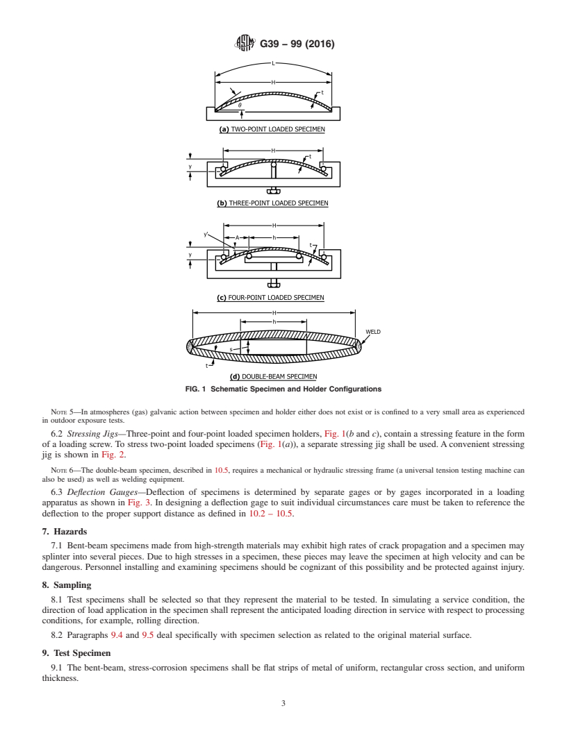
on the specimen. Typical specimen holder configurations are shown schematically in Fig. 1.
NOTE 2—The double-beam specimen, more fully described in 10.5, is self-contained and does not require a holder.
NOTE 3—Specimen holders can be modified from the constant deformation type shown in Fig. 1 to give a constant-load type of stressing. For instance,
the loading bolt can be supplanted by a spring or deadweight arrangement to change the mode of loading.
6.1.1 The holder shall be made of a material that would withstand the influence of the environment without deterioration or
change in shape.
NOTE 4—It should be recognized that many plastics tend to creep when subjected to sustained loads. If specimen holders or insulators are made of
such materials, the applied stress on the specimen may change appreciably with time. By proper choice of holder and insulator materials, however, many
plastics can be used, especially in short-time tests.
6.1.2 When the stress-corrosion test is conducted by immersion in an electrolyte, galvanic action between specimen and holder
(or spacer) shall be prevented (see Note 5). This is accomplished by (1) making the holder of the same material as the individual
specimens, (2) inserting electrically insulating materials between specimen and holder at all points of contact (see Note 4), (3)
making the entire holder out of a nonmetallic material (see Note 4), or (4) coating the holder with an electrically nonconducting
coating that effectively prevents contact between holder and electrolyte.
6.1.3 Crevice corrosion may occur in an electrolyte at contact points between specimen and holder (or spacer). In these instances
the critical areas should be packed with a hydrophobic filler (such as grease or wax).
G39 − 99 (2016)
FIG. 1 Schematic Specimen and Holder Configurations
NOTE 5—In atmospheres (gas) galvanic action between specimen and holder either does not exist or is confined to a very small area as experienced
in outdoor exposure tests.
6.2 Stressing Jigs—Three-point and four-point loaded specimen holders, Fig. 1(b and c), contain a stressing feature in the form
of a loading screw. To stress two-point loaded specimens (Fig. 1(a)), a separate stressing jig shall be used. A convenient stressing
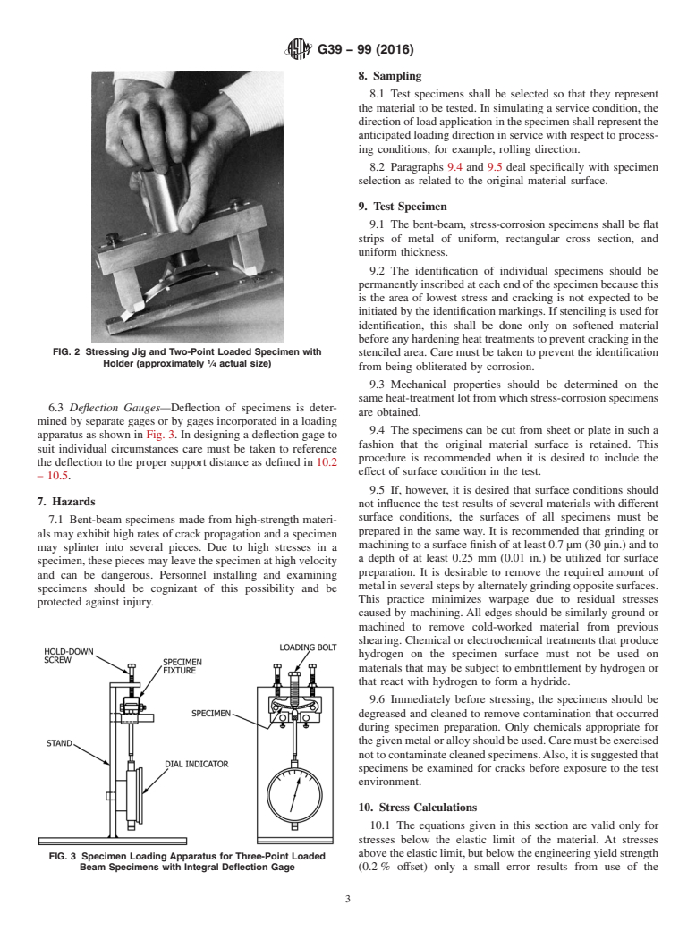
jig is shown in Fig. 2.
NOTE 6—The double-beam specimen, described in 10.5, requires a mechanical or hydraulic stressing frame (a universal tension testing machine can
also be used) as well as welding equipment.
6.3 Deflection Gauges—Deflection of specimens is determined by separate gages or by gages incorporated in a loading
apparatus as shown in Fig. 3. In designing a deflection gage to suit individual circumstances care must be taken to reference the
deflection to the proper support distance as defined in 10.2 – 10.5.
7. Hazards
7.1 Bent-beam specimens made from high-strength materials may exhibit high rates of crack propagation and a specimen may
splinter into several pieces. Due to high stresses in a specimen, these pieces may leave the specimen at high velocity and can be
dangerous. Personnel installing and examining specimens should be cognizant of this possibility and be protected against injury.
8. Sampling
8.1 Test specimens shall be selected so that they represent the material to be tested. In simulating a service condition, the
direction of load application in the specimen shall represent the anticipated loading direction in service with respect to processing
conditions, for example, rolling direction.
8.2 Paragraphs 9.4 and 9.5 deal specifically with specimen selection as related to the original material surface.
9. Test Specimen
9.1 The bent-beam, stress-corrosion specimens shall be flat strips of metal of uniform, rectangular cross section, and uniform
thickness.
G39 − 99 (2016)
FIG. 2 Stressing Jig and Two-Point Loaded Specimen with Holder (approximately ⁄4 actual size)
FIG. 3 Specimen Loading Apparatus for Three-Point Loaded Beam Specimens with Integral Deflection Gage
9.2 The identification of individual specimens should be permanently inscribed at each end of the specimen because this is the
area of lowest stress and cracking is not expected to be initiated by the identification markings. If stenciling is used for
identification, this shall be done only on softened material before any hardening heat treatments to prevent cracking in the stenciled
area. Care must be taken to prevent the identification from being obliterated by corrosion.
9.3 Mechanical properties should be determined on the same heat-treatment lot from which stress-corrosion specimens are
obtained.
9.4 The specimens can be cut from sheet or plate in such a fashion that the original material surface is retained. This procedure
is recommended when it is desired to include the effect of surface condition in the test.
9.5 If, however, it is desired that surface conditions should not influence the test results of several materials with different
surface conditions, the surfaces of all specimens must be prepared in the same way. It is recommended that grinding or machining
to a surface finish of at least 0.7 μm (30 μin.) and to a depth of at least 0.25 mm (0.01 in.) be utilized for surface preparation. It
is desirable to remove the required amount of metal in several steps by alternately grinding opposite surfaces. This practice
minimizes warpage due to residual stresses caused by machining. All edges should be similarly ground or machined to remove
cold-worked material from previous shearing. Chemical or electrochemical treatments that produce hydrogen on the specimen
surface must not be used on materials that may be subject to embrittlement by hydrogen or that react with hydrogen to form a
hydride.
G39 − 99 (2016)
9.6 Immediately before stressing, the specimens should be degreased and cleaned to remove contamination that occurred during
specimen preparation. Only chemicals appropriate for the given metal or alloy should be used. Care must be exercised not to
contaminate cleaned specimens. Also, it is suggested that specimens be examined for cracks before exposure to the test
environment.
10. Stress Calculations
10.1 The equations given in this section are valid only for stresses below the elastic limit of the material. At stresses above the
elastic limit, but below the engineering yield strength (0.2 % offset) only a small error results from use of the equations (see Note
1). The equations must not be used above the yield strength of the material. The following paragraphs give relationships used to
calculate the maximum longitudinal stress in the outer fibers of the specimen convex surface. Calculations for transverse stress or
edge-to-edge variation of longitudinal stress are not given; the specimen dimensions are chosen to minimize these stresses
consistent with convenient use of the specimens. The specimen dimensions given here can be modified to suit specific needs.
However, if this is done, the approximate specimen proportions should be preserved to give a similar stress distribution (for
instance, if the length is doubled the width should be doubled also).
10.1.1 When specimens are tested at elevated temperatures, the possibility of stress relaxation should be investigated.
Relaxation can be estimated from known creep data for the specimen, holder, and insulating materials.
...
Questions, Comments and Discussion
Ask us and Technical Secretary will try to provide an answer. You can facilitate discussion about the standard in here.