


ASTM F1673-10(2016)
(Specification)Standard Specification for Polyvinylidene Fluoride (PVDF) Corrosive Waste Drainage Systems
Standard Specification for Polyvinylidene Fluoride (PVDF) Corrosive Waste Drainage Systems
ABSTRACT
This specification covers requirements for polyvinylidene drainage systems for corrosive applications. Requirements for material, pipe and fittings are included. Polyvinylidene fluoride includes emulsion/suspension polymerization and copolymers of vinylidene fluoride/hexafluoropropylene produced by either method. These requirements apply to Schedule 40 and 80 IPS and SDR 21 pipe sizes. Pipe and fittings are to be joined by heat fusion or mechanical methods. The following tests shall be performed: chemical resistance; water absorption; joint tests – hydrostatic pressure tests; mechanical joint pullout test; threads; flattening; and impact resistance for PVDF pipe and fittings.
SCOPE
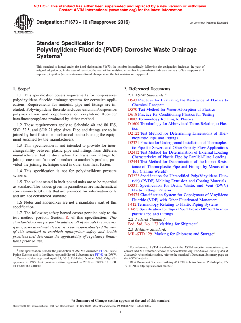
1.1 This specification covers requirements for nonpressurepolyvinylidene fluoride drainage systems for corrosive applications. Requirements for material, pipe and fittings are included. Polyvinylidene fluoride includes emulsion/suspension polymerization and copolymers of vinylidene fluoride/hexafluoropropylene produced by either method.
1.2 These requirements apply to Schedule 40 and 80 IPS, SDR 32.5, and SDR 21 pipe sizes. Pipe and fittings are to be joined by heat fusion or mechanical methods using the equipment supplied by the manufacturers.
1.3 This specification is not intended to provide for interchangeability between plastic pipe and fittings from different manufacturers, but it does allow for transition fittings for joining one manufacturer's product to another's product, provided the joining technique used is other than heat fusion.
1.4 This specification is not for polyvinylidene pressure systems.
1.5 The values stated in inch-pound units are to be regarded as standard. The values given in parentheses are mathematical conversions to SI units that are provided for information only and are not considered standard.
1.6 Notes and appendixes are not a mandatory part of this specification.
1.7 The following safety hazard caveat pertains only to the test method portion, Section 8, of this specification: This standard does not purport to address all of the safety concerns, if any, associated with its use. It is the responsibility of the user of this standard to establish appropriate safety and health practices and determine the applicability of regulatory limitations prior to use.
General Information
Buy Standard
Standards Content (Sample)
NOTICE: This standard has either been superseded and replaced by a new version or withdrawn.
Contact ASTM International (www.astm.org) for the latest information
Designation:F1673 −10 (Reapproved 2016) An American National Standard
Standard Specification for
Polyvinylidene Fluoride (PVDF) Corrosive Waste Drainage
Systems
This standard is issued under the fixed designation F1673; the number immediately following the designation indicates the year of
original adoption or, in the case of revision, the year of last revision.Anumber in parentheses indicates the year of last reapproval.A
superscript epsilon (´) indicates an editorial change since the last revision or reapproval.
1. Scope* 2. Referenced Documents
1.1 This specification covers requirements for nonpressure- 2.1 ASTM Standards:
polyvinylidene fluoride drainage systems for corrosive appli- D543Practices for Evaluating the Resistance of Plastics to
cations. Requirements for material, pipe and fittings are in- Chemical Reagents
cluded. Polyvinylidene fluoride includes emulsion/suspension
D570Test Method for Water Absorption of Plastics
polymerization and copolymers of vinylidene fluoride/ D618Practice for Conditioning Plastics for Testing
hexafluoropropylene produced by either method.
D883Terminology Relating to Plastics
D1600TerminologyforAbbreviatedTermsRelatingtoPlas-
1.2 These requirements apply to Schedule 40 and 80 IPS,
tics
SDR 32.5, and SDR 21 pipe sizes. Pipe and fittings are to be
D2122Test Method for Determining Dimensions of Ther-
joined by heat fusion or mechanical methods using the equip-
moplastic Pipe and Fittings
ment supplied by the manufacturers.
D2321PracticeforUndergroundInstallationofThermoplas-
1.3 This specification is not intended to provide for inter-
tic Pipe for Sewers and Other Gravity-Flow Applications
changeability between plastic pipe and fittings from different
D2412Test Method for Determination of External Loading
manufacturers, but it does allow for transition fittings for
Characteristics of Plastic Pipe by Parallel-Plate Loading
joining one manufacturer’s product to another’s product, pro-
D2444Test Method for Determination of the Impact Resis-
vided the joining technique used is other than heat fusion.
tance of Thermoplastic Pipe and Fittings by Means of a
1.4 This specification is not for polyvinylidene pressure
Tup (Falling Weight)
systems.
D3222Specification for Unmodified Poly(Vinylidene Fluo-
ride) (PVDF) Molding Extrusion and Coating Materials
1.5 The values stated in inch-pound units are to be regarded
D3311Specification for Drain, Waste, and Vent (DWV)
as standard. The values given in parentheses are mathematical
Plastic Fittings Patterns
conversions to SI units that are provided for information only
D5575Classification System for Copolymers of Vinylidene
and are not considered standard.
Fluoride (VDF) with Other Fluorinated Monomers
1.6 Notes and appendixes are not a mandatory part of this
F412Terminology Relating to Plastic Piping Systems
specification.
F1498SpecificationforTaperPipeThreads60°forThermo-
1.7 The following safety hazard caveat pertains only to the
plastic Pipe and Fittings
test method portion, Section 8, of this specification: This
2.2 Federal Standard:
standard does not purport to address all of the safety concerns, 3
Fed. Std. No. 123Marking for Shipment
if any, associated with its use. It is the responsibility of the user
2.3 Military Standard:
of this standard to establish appropriate safety and health
MIL-STD129 Marking for Shipment and Storage
practices and determine the applicability of regulatory limita-
tions prior to use.
For referenced ASTM standards, visit the ASTM website, www.astm.org, or
This specification is under the jurisdiction ofASTM Committee F17 on Plastic contact ASTM Customer Service at service@astm.org. For Annual Book of ASTM
Piping Systems and is the direct responsibility of Subcommittee F17.63 on DWV. Standards volume information, refer to the standard’s Document Summary page on
Current edition approved April 15, 2016. Published October 2016. Originally the ASTM website.
approved in 1995. Last previous edition approved in 2010 as F1673-10. DOI: DLA Document Services Building 4/D 700 Robbins Avenue Philadelphia, PA
10.1520/F1673-10R16. 19111-5094 http://quicksearch.dla.mil/
*A Summary of Changes section appears at the end of this standard
Copyright © ASTM International, 100 Barr Harbor Drive, PO Box C700, West Conshohocken, PA 19428-2959. United States
F1673−10 (2016)
2.4 Other Standard: 6.1.1.2 Toe-In—The outside diameter, when measured in
Uniform Plumbing Code accordance with Method D2122, shall meet the requirements
of Table 1 and Table 2 at any point within 1.5 pipe diameters
3. Terminology
or 11.8 in. (300 mm), whichever is less, to the cut end of the
pipe length.
3.1 Definitions:
6.1.2 Fittings:
3.1.1 Definitionsusedinthisspecificationareinaccordance
withthedefinitionsgiveninTerminologiesD883andF412and 6.1.2.1 The minimum wall thickness of the body all fittings
shall not be less than the corresponding Schedule 40 pipe size
abbreviations are in accordance with Terminology D1600,
unless otherwise indicated. and shall be measured in accordance with Method D2122.
6.1.2.2 Spigot ends of fittings shall conform to the diameter
3.1.2 Theplumbingterminologyusedinthisspecificationis
in accordance with the definitions given in the Uniform and out-of-roundness requirements for pipe.
6.1.2.3 Socket ends of fittings shall conform to the dimen-
Plumbing Code, unless otherwise indicated.
sional requirements for size and tolerances as provided by the
4. Classification
manufacturer.
6.1.2.4 The average minimum diameters of waterways of
4.1 General—This specification covers PVDF pipe and
fittings, excluding adapters, shall be as specified in Table 3.
fittings made from PVDF or VF/HFP copolymers in Schedule
6.1.2.5 Taper pipe threads in any fittings shall be as speci-
40 and 80 and SDR 32.5 and SDR 21 IPS sizes.
fied in Specification F1498.The tolerance shall be 1 ⁄2 large or
4.2 This specification also includes molded fittings and the
small turns from the basic thread dimension and gaged in
larger sizes (8, 10, 12 in.) of fabricated fittings.
accordance with 8.7.
6.1.2.6 The patterns, dimensions, and laying lengths of
5. Materials and Manufacture
molded fittings, including adaptors, shall meet the require-
5.1 Polyvinylidene fluoride (PVDF) material for pipe or
ments of Specification D3311, or shall be of a proven design
fittings shall conform to the requirements of Type I Grade 1,
and allow a smooth transition of fluid flow from one direction
Type I Grade 2, or Type II PVDF as defined in Specification
to another.
D3222 or copolymers as defined in Specification D5575.
6.1.2.7 Cleanouts, cleanout plugs, and caps as commonly
5.2 The PVDF material may contain pigment and fillers not
used in the manufacturer’s laboratory drainage system, shall
detrimental to the pipe and fittings, provided the pipe and
have a thread size and depth sufficient to ensure that the
fittings produced meet the requirements of this specification.
minimum waterway sizes are maintained.
6.1.2.8 Traps—Alltrapsshallhaveaminimumwatersealof
5.3 Rework Material—Clean rework material, generated
2 in.
fromthemanufacturer’spipeandfittingsproductsmaybeused
by the same manufacturer, provided that the pipe or fittings
6.2 Chemical Resistance—Pipeandfittingsmaterialshallbe
produced meet the requirements of this specification.
evaluated in accordance with Practice D543, Procedures I and
II, using the chemicals listed in 8.3. The weight change shall
6. Requirements
not exceed 2%, nor shall the apparent tensile strength change
6.1 Dimensions and Tolerances—Pipe and Fittings:
by more than 10%. In cases where there is a change in the
6.1.1 Pipe:
apparenttensilestrengthgreaterthan10%,afurtherevaluation
6.1.1.1 Dimensions and tolerances for pipe shown in Table
shall be made after removal from the chemical and condition-
1 and Table 2 shall be measured in accordance with Method
ing for 72 h. If there is a minimum of 50% recovery of tensile
D2122. The tolerance for out-of-roundness shall apply only to
strength after 72 h, and that figure is within 610% of the
pipe prior to shipment.
original tensile strength, the specimen shall be considered
acceptable.
6.3 Water Absorption—Pipe and fitting materials shall not
Available from International Association of Plumbing and Mechanical
Officials, 5001 E. Philadelphia St., Ontario, CA 91761, http://www.iapmo.org. change in weight more than 0.50% when tested in accordance
with 8.4.
TABLE 1 Outside Diameters and Tolerances for PVDF Pipe
6.4 System Integrity:
Schedules 40 and 80 and SDR 21, in. (mm)
6.4.1 Fused joints and associated pipe shall withstand a
Nominal Pipe Average Outside Tolerance Out-of-Roundness
pressure of 50 psi (345 kPa) without leaking when tested in
Size Diameter (Maximum Diameter
accordance with 8.5.1.
Minus Minimum
Diameter)
6.4.2 Mechanical joints shall withstand a pressure of 14.5
1 ⁄4 1.660 (42.16) ±0.005 (±0.13) 0.050 (1.28)
psi (100 kPa) without leaking when tested in accordance with
1 ⁄2 1.900 (48.26) ±0.006 (±0.15) 0.060 (1.52)
8.5.2.
2 2.375 (60.32) ±0.006 (±0.15) 0.070 (1.78)
3 3.500 (88.90) ±0.008 (±0.20) 0.080 (2.04)
NOTE 1—Mechanical joints include transition, compression, threaded,
4 4.500 (114.30) ±0.009 (±0.23) 0.100 (2.54)
and other type mechanical joints.
6 6.625 (168.28) ±0.011 (±0.28) 0.100 (2.54)
8 8.625 (219.08) ±0.015 (±0.38) 0.150 (3.80)
6.4.3 Mechanical joints shall incorporate a positive me-
10 10.750 (273.05) ±0.015 (±0.38) 0.150 (3.80)
chanical system for axial restraint in addition to any restraint
12 12.750 (323.85) ±0.015 (±0.38) 0.150 (3.80)
provided by friction.
F1673−10 (2016)
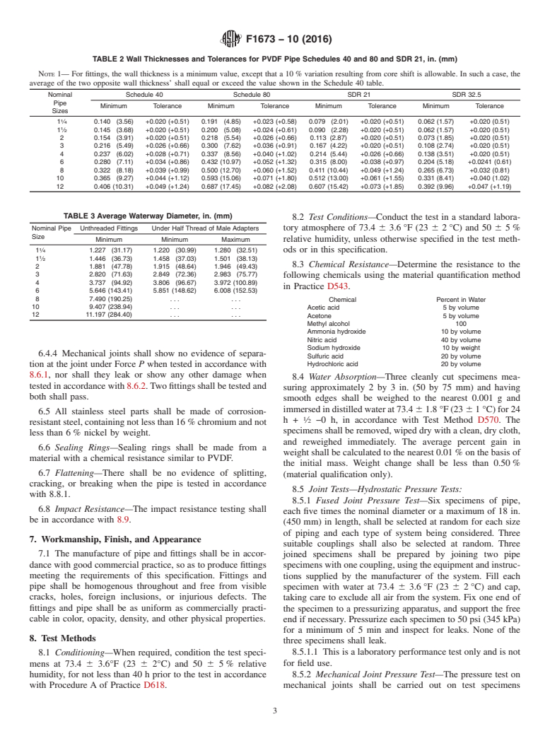
TABLE 2 Wall Thicknesses and Tolerances for PVDF Pipe Schedules 40 and 80 and SDR 21, in. (mm)
NOTE 1— For fittings, the wall thickness is a minimum value, except that a 10% variation resulting from core shift is allowable. In such a case, the
average of the two opposite wall thickness’ shall equal or exceed the value shown in the Schedule 40 table.
Nominal Schedule 40 Schedule 80 SDR 21 SDR 32.5
Pipe
Minimum Tolerance Minimum Tolerance Minimum Tolerance Minimum Tolerance
Sizes
1 ⁄4 0.140 (3.56) +0.020 (+0.51) 0.191 (4.85) +0.023 (+0.58) 0.079 (2.01) +0.020 (+0.51) 0.062 (1.57) +0.020 (0.51)
1 ⁄2 0.145 (3.68) +0.020 (+0.51) 0.200 (5.08) +0.024 (+0.61) 0.090 (2.28) +0.020 (+0.51) 0.062 (1.57) +0.020 (0.51)
2 0.154 (3.91) +0.020 (+0.51) 0.218 (5.54) +0.026 (+0.66) 0.113 (2.87) +0.020 (+0.51) 0.073 (1.85) +0.020 (0.51)
3 0.216 (5.49) +0.026 (+0.66) 0.300 (7.62) +0.036 (+0.91) 0.167 (4.22) +0.020 (+0.51) 0.108 (2.74) +0.020 (0.51)
4 0.237 (6.02) +0.028 (+0.71) 0.337 (8.56) +0.040 (+1.02) 0.214 (5.44) +0.026 (+0.66) 0.138 (3.51) +0.020 (0.51)
6 0.280 (7.11) +0.034 (+0.86) 0.432 (10.97) +0.052 (+1.32) 0.315 (8.00) +0.038 (+0.97) 0.204 (5.18) +0.0241 (0.61)
8 0.322 (8.18) +0.039 (+0.99) 0.500 (12.70) +0.060 (+1.52) 0.411 (10.44) +0.049 (+1.24) 0.265 (6.73) +0.032 (0.81)
10 0.365 (9.27) +0.044 (+1.12) 0.593 (15.06) +0.071 (+1.80) 0.512 (13.00) +0.061 (+1.55) 0.331 (8.41) +0.040 (1.02)
12 0.406 (10.31) +0.049 (+1.24) 0.687 (17.45) +0.082 (+2.08) 0.607 (15.42) +0.073 (+1.85) 0.392 (9.96) +0.047 (+1.19)
TABLE 3 Average Waterway Diameter, in. (mm)
8.2 Test Conditions—Conduct the test in a standard labora-
Nominal Pipe Unthreaded Fittings Under Half Thread of Male Adapters tory atmosphere of 73.4 6 3.6°F (23 6 2°C) and 50 65%
Size
Minimum Minimum Maximum relative humidity, unless otherwise specified in the test meth-
1 ⁄4 1.227 (31.17) 1.220 (30.99) 1.280 (32.51) ods or in this specification.
1 ⁄2 1.446 (36.73) 1.458 (37.03) 1.501 (38.13)
8.3 Chemical Resistance—Determine the resistance to the
2 1.881 (47.78) 1.915 (48.64) 1.946 (49.43)
3 2.820 (71.63) 2.849 (72.36) 2.983 (75.77)
following chemicals using the material quantification method
4 3.737 (94.92) 3.806 (96.67) 3.972 (100.89)
in Practice D543.
6 5.646 (143.41) 5.851 (148.62) 6.008 (152.53)
8 7.490 (190.25) . . . . . .
Chemical Percent in Water
10 9.407 (238.94) . . . . . .
Acetic acid 5 by volume
12 11.197 (284.40) . . . . . .
Acetone 5 by volume
Methyl alcohol 100
Ammonia hydroxide 10 by volume
Nitric acid 40 by volume
Sodium hydroxide 10 by weight
6.4.4 Mechanical joints shall show no evidence of separa-
Sulfuric acid 20 by volume
Hydrochloric acid 20 by volume
tion at the joint under Force P when tested in accordance with
8.6.1, nor shall they leak or show any other damage when
8.4 Water Absorption—Three cleanly cut specimens mea-
testedinaccordancewith8.6.2.Twofittingsshallbetestedand
suring approximately 2 by 3 in. (50 by 75 mm) and having
both shall pass.
smooth edges shall be weighed to the nearest 0.001 g and
immersedindistilledwaterat73.4 61.8°F(23 61°C)for24
6.5 All stainless steel parts shall be made of corrosion-
h+ ⁄2 −0 h, in accordance with Test Method D570. The
resistantsteel,containingnotlessthan16%chromiumandnot
specimensshallberemoved,wipeddrywithaclean,drycloth,
less than 6% nickel by weight.
and reweighed immediately. The average percent gain in
6.6 Sealing Rings—Sealing rings shall be made from a
weight shall be calculated to the nearest 0.01% on the basis of
material with a chemical resistance similar to PVDF.
the initial mass. Weight change shall be less than 0.50%
6.7 Flattening—There shall be no evidence of splitting,
(material qualification only).
cracking, or breaking when the pipe is tested in accordance
8.5 Joint Tests—Hydrostatic Pressure Tests:
with 8.8.1.
8.5.1 Fused Joint Pressure Test—Six specimens of pipe,
6.8 Impact Resistance—The impact resistance testing shall
each five times the nominal diameter or a maximum of 18 in.
be in accordance with 8.9.
(450 mm) in length, shall be selected at random for each size
of piping and each type of system being considered. Three
7. Workmanship, Finish, and Appearance
suitable couplings shall also be selected at random. Three
7.1 The manufacture of pipe and fittings shall be in accor- joined specimens shall be prepared by joining two pipe
dance with good commercial practice, so as to produce fittings
specimenswithonecoupling,usingtheequipmentandinstruc-
meeting the requirements of this specification. Fittings and tions supplied by the manufacturer of the system. Fill each
pipe shall be homogenous throughout and free from visible
specimen with water at 73.4 6 3.6°F (23 6 2°C) and cap,
cracks, holes, foreign inclusions, or injurious defects. The taking care to exclude all air from the system. Fix one end of
fittings and pipe shall be as uniform as commercially practi-
the specimen to a pressurizing apparatus, and support the free
cable in color, opacity, density, and other physical properties.
end if necessary. Pressurize each specimen to 50 psi (345 kPa)
for a minimum of 5 min and inspect for leaks. None of the
8. Test Methods
three specimens shall leak.
8.5.1.1 This is a la
...
This document is not an ASTM standard and is intended only to provide the user of an ASTM standard an indication of what changes have been made to the previous version. Because
it may not be technically possible to adequately depict all changes accurately, ASTM recommends that users consult prior editions as appropriate. In all cases only the current version
of the standard as published by ASTM is to be considered the official document.
Designation: F1673 − 10 F1673 − 10 (Reapproved 2016) An American National Standard
Standard Specification for
Polyvinylidene Fluoride (PVDF) Corrosive Waste Drainage
Systems
This standard is issued under the fixed designation F1673; the number immediately following the designation indicates the year of
original adoption or, in the case of revision, the year of last revision. A number in parentheses indicates the year of last reapproval. A
superscript epsilon (´) indicates an editorial change since the last revision or reapproval.
1. Scope*
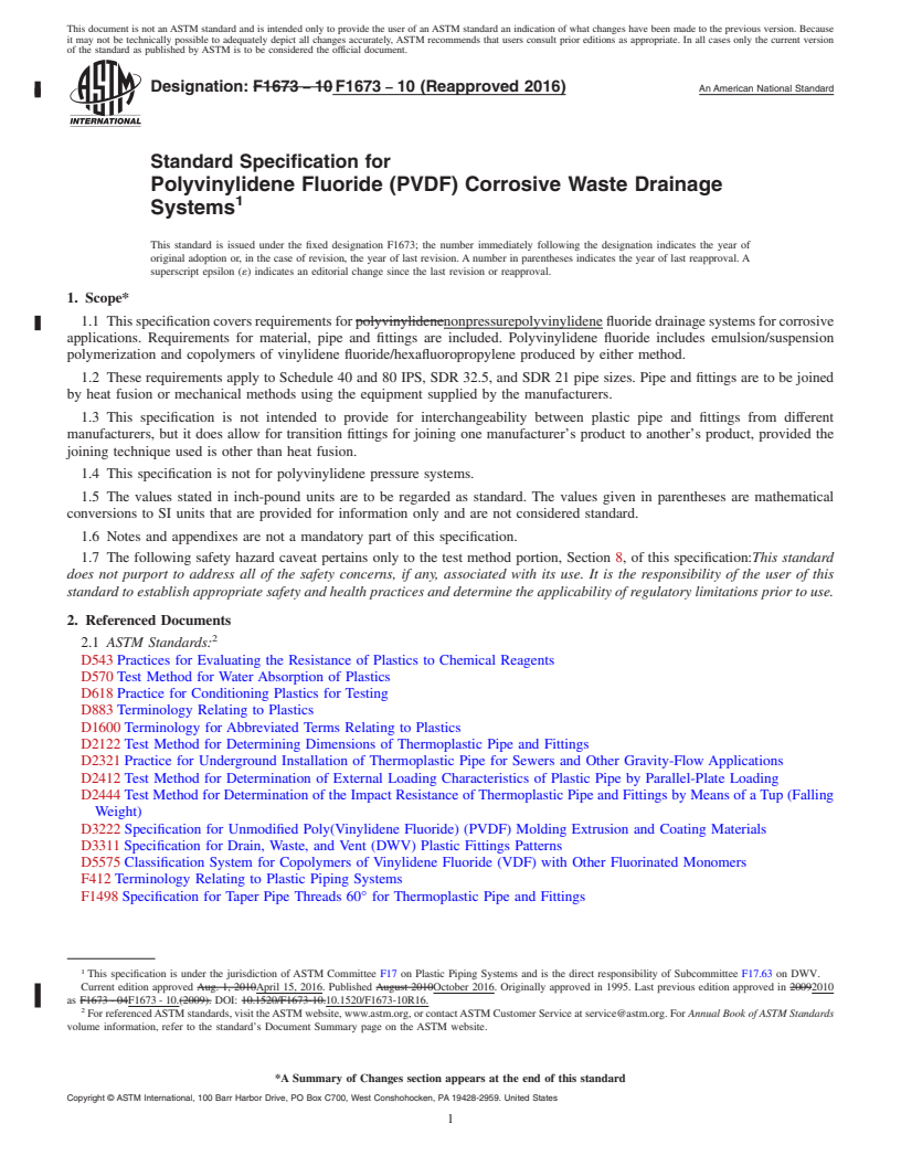
1.1 This specification covers requirements for polyvinylidenenonpressurepolyvinylidene fluoride drainage systems for corrosive
applications. Requirements for material, pipe and fittings are included. Polyvinylidene fluoride includes emulsion/suspension
polymerization and copolymers of vinylidene fluoride/hexafluoropropylene produced by either method.
1.2 These requirements apply to Schedule 40 and 80 IPS, SDR 32.5, and SDR 21 pipe sizes. Pipe and fittings are to be joined
by heat fusion or mechanical methods using the equipment supplied by the manufacturers.
1.3 This specification is not intended to provide for interchangeability between plastic pipe and fittings from different
manufacturers, but it does allow for transition fittings for joining one manufacturer’s product to another’s product, provided the
joining technique used is other than heat fusion.
1.4 This specification is not for polyvinylidene pressure systems.
1.5 The values stated in inch-pound units are to be regarded as standard. The values given in parentheses are mathematical
conversions to SI units that are provided for information only and are not considered standard.
1.6 Notes and appendixes are not a mandatory part of this specification.
1.7 The following safety hazard caveat pertains only to the test method portion, Section 8, of this specification:This standard
does not purport to address all of the safety concerns, if any, associated with its use. It is the responsibility of the user of this
standard to establish appropriate safety and health practices and determine the applicability of regulatory limitations prior to use.
2. Referenced Documents
2.1 ASTM Standards:
D543 Practices for Evaluating the Resistance of Plastics to Chemical Reagents
D570 Test Method for Water Absorption of Plastics
D618 Practice for Conditioning Plastics for Testing
D883 Terminology Relating to Plastics
D1600 Terminology for Abbreviated Terms Relating to Plastics
D2122 Test Method for Determining Dimensions of Thermoplastic Pipe and Fittings
D2321 Practice for Underground Installation of Thermoplastic Pipe for Sewers and Other Gravity-Flow Applications
D2412 Test Method for Determination of External Loading Characteristics of Plastic Pipe by Parallel-Plate Loading
D2444 Test Method for Determination of the Impact Resistance of Thermoplastic Pipe and Fittings by Means of a Tup (Falling
Weight)
D3222 Specification for Unmodified Poly(Vinylidene Fluoride) (PVDF) Molding Extrusion and Coating Materials
D3311 Specification for Drain, Waste, and Vent (DWV) Plastic Fittings Patterns
D5575 Classification System for Copolymers of Vinylidene Fluoride (VDF) with Other Fluorinated Monomers
F412 Terminology Relating to Plastic Piping Systems
F1498 Specification for Taper Pipe Threads 60° for Thermoplastic Pipe and Fittings
This specification is under the jurisdiction of ASTM Committee F17 on Plastic Piping Systems and is the direct responsibility of Subcommittee F17.63 on DWV.
Current edition approved Aug. 1, 2010April 15, 2016. Published August 2010October 2016. Originally approved in 1995. Last previous edition approved in 20092010
as F1673 - 04F1673 - 10.(2009). DOI: 10.1520/F1673-10.10.1520/F1673-10R16.
For referenced ASTM standards, visit the ASTM website, www.astm.org, or contact ASTM Customer Service at service@astm.org. For Annual Book of ASTM Standards
volume information, refer to the standard’s Document Summary page on the ASTM website.
*A Summary of Changes section appears at the end of this standard
Copyright © ASTM International, 100 Barr Harbor Drive, PO Box C700, West Conshohocken, PA 19428-2959. United States
F1673 − 10 (2016)
2.2 Federal Standard:
Fed. Std. No. 123 Marking for Shipment
2.3 Military Standard:
MIL-STD 129 Marking for Shipment and Storage
2.4 Other Standard:
Uniform Plumbing Code
3. Terminology
3.1 Definitions:
3.1.1 Definitions used in this specification are in accordance with the definitions given in Terminologies D883 and F412 and
abbreviations are in accordance with Terminology D1600, unless otherwise indicated.
3.1.2 The plumbing terminology used in this specification is in accordance with the definitions given in the Uniform Plumbing
Code, unless otherwise indicated.
3.1 Definitions:
3.1.1 Definitions used in this specification are in accordance with the definitions given in Terminologies D883 and F412 and
abbreviations are in accordance with Terminology D1600, unless otherwise indicated.
3.1.2 The plumbing terminology used in this specification is in accordance with the definitions given in the Uniform Plumbing
Code, unless otherwise indicated.
4. Classification
4.1 General—This specification covers PVDF pipe and fittings made from PVDF or VF/HFP copolymers in Schedule 40 and
80 IPS sizes and in SDR 32.5 and SDR 21. 21 IPS sizes.
4.2 This specification also includes molded fittings and the larger sizes (8, 10, 12 in.) of fabricated fittings.
5. Materials and Manufacture
5.1 Polyvinylidene fluoride (PVDF) material for pipe or fittings shall conform to the requirements of Type I Grade 1, Type I
Grade 2, or Type II PVDF as defined in Specification D3222 or copolymers as defined in Specification D5575.
5.2 The PVDF material may contain pigment and fillers not detrimental to the pipe and fittings, provided the pipe and fittings
produced meet the requirements of this specification.
5.3 Rework Material—Clean rework material, generated from the manufacturer’s pipe and fittings products may be used by the
same manufacturer, provided that the pipe or fittings produced meet the requirements of this specification.
6. Requirements
6.1 Dimensions and Tolerances—Pipe and Fittings:
6.1.1 Pipe:
6.1.1.1 Dimensions and tolerances for pipe shown in Table 1 and Table 2 shall be measured in accordance with Method D2122.
The tolerance for out-of-roundness shall apply only to pipe prior to shipment.
6.1.1.2 Toe-In—The outside diameter, when measured in accordance with Method D2122, shall meet the requirements of Table
1 and Table 2 at any point within 1.5 pipe diameters or 11.8 in. (300 mm), whichever is less, to the cut end of the pipe length.
Available from Standardization Documents Order Desk, DODSSP, Bldg. 4, Section D, 700 Robbins Ave., Philadelphia, PA 19111-5098, http://www.dodssp.daps.mil.DLA
Document Services Building 4/D 700 Robbins Avenue Philadelphia, PA 19111-5094 http://quicksearch.dla.mil/
Available from International Association of Plumbing and Mechanical Officials, 5001 E. Philadelphia St., Ontario, CA 91761, http://www.iapmo.org.
TABLE 1 Outside Diameters and Tolerances for PVDF Pipe
Schedules 40 and 80 and SDR 21, in. (mm)
Nominal Pipe Average Outside Tolerance Out-of-Roundness
Size Diameter (Maximum Diameter
Minus Minimum
Diameter)
1 ⁄4 1.660 (42.16) ±0.005 (±0.13) 0.050 (1.28)
1 ⁄2 1.900 (48.26) ±0.006 (±0.15) 0.060 (1.52)
2 2.375 (60.32) ±0.006 (±0.15) 0.070 (1.78)
3 3.500 (88.90) ±0.008 (±0.20) 0.080 (2.04)
4 4.500 (114.30) ±0.009 (±0.23) 0.100 (2.54)
6 6.625 (168.28) ±0.011 (±0.28) 0.100 (2.54)
8 8.625 (219.08) ±0.015 (±0.38) 0.150 (3.80)
10 10.750 (273.05) ±0.015 (±0.38) 0.150 (3.80)
12 12.750 (323.85) ±0.015 (±0.38) 0.150 (3.80)
F1673 − 10 (2016)
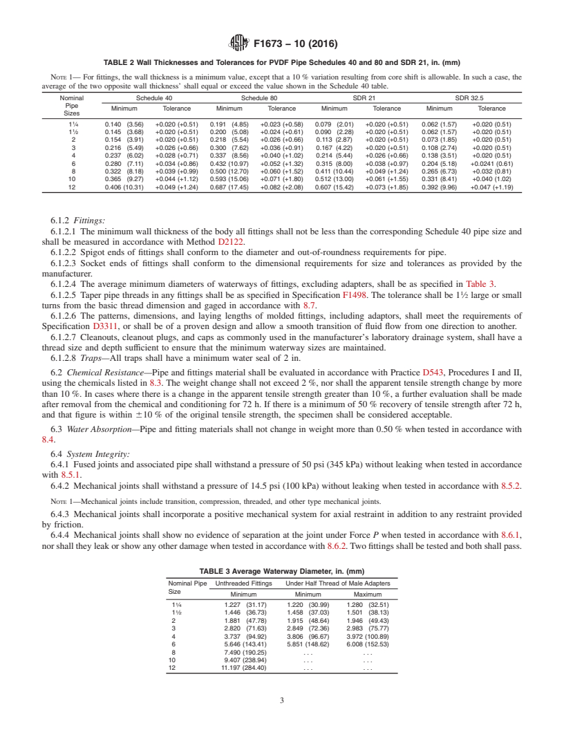
TABLE 2 Wall Thicknesses and Tolerances for PVDF Pipe Schedules 40 and 80 and SDR 21, in. (mm)
NOTE 1— For fittings, the wall thickness is a minimum value, except that a 10 % variation resulting from core shift is allowable. In such a case, the
average of the two opposite wall thickness’ shall equal or exceed the value shown in the Schedule 40 table.
Nominal Schedule 40 Schedule 80 SDR 21 SDR 32.5
Pipe
Minimum Tolerance Minimum Tolerance Minimum Tolerance Minimum Tolerance
Sizes
1 ⁄4 0.140 (3.56) +0.020 (+0.51) 0.191 (4.85) +0.023 (+0.58) 0.079 (2.01) +0.020 (+0.51) 0.062 (1.57) +0.020 (0.51)
1 ⁄2 0.145 (3.68) +0.020 (+0.51) 0.200 (5.08) +0.024 (+0.61) 0.090 (2.28) +0.020 (+0.51) 0.062 (1.57) +0.020 (0.51)
2 0.154 (3.91) +0.020 (+0.51) 0.218 (5.54) +0.026 (+0.66) 0.113 (2.87) +0.020 (+0.51) 0.073 (1.85) +0.020 (0.51)
3 0.216 (5.49) +0.026 (+0.66) 0.300 (7.62) +0.036 (+0.91) 0.167 (4.22) +0.020 (+0.51) 0.108 (2.74) +0.020 (0.51)
4 0.237 (6.02) +0.028 (+0.71) 0.337 (8.56) +0.040 (+1.02) 0.214 (5.44) +0.026 (+0.66) 0.138 (3.51) +0.020 (0.51)
6 0.280 (7.11) +0.034 (+0.86) 0.432 (10.97) +0.052 (+1.32) 0.315 (8.00) +0.038 (+0.97) 0.204 (5.18) +0.0241 (0.61)
8 0.322 (8.18) +0.039 (+0.99) 0.500 (12.70) +0.060 (+1.52) 0.411 (10.44) +0.049 (+1.24) 0.265 (6.73) +0.032 (0.81)
10 0.365 (9.27) +0.044 (+1.12) 0.593 (15.06) +0.071 (+1.80) 0.512 (13.00) +0.061 (+1.55) 0.331 (8.41) +0.040 (1.02)
12 0.406 (10.31) +0.049 (+1.24) 0.687 (17.45) +0.082 (+2.08) 0.607 (15.42) +0.073 (+1.85) 0.392 (9.96) +0.047 (+1.19)
6.1.2 Fittings:
6.1.2.1 The minimum wall thickness of the body all fittings shall not be less than the corresponding Schedule 40 pipe size and
shall be measured in accordance with Method D2122.
6.1.2.2 Spigot ends of fittings shall conform to the diameter and out-of-roundness requirements for pipe.
6.1.2.3 Socket ends of fittings shall conform to the dimensional requirements for size and tolerances as provided by the
manufacturer.
6.1.2.4 The average minimum diameters of waterways of fittings, excluding adapters, shall be as specified in Table 3.
6.1.2.5 Taper pipe threads in any fittings shall be as specified in Specification F1498. The tolerance shall be 1 ⁄2 large or small
turns from the basic thread dimension and gaged in accordance with 8.7.
6.1.2.6 The patterns, dimensions, and laying lengths of molded fittings, including adaptors, shall meet the requirements of
Specification D3311, or shall be of a proven design and allow a smooth transition of fluid flow from one direction to another.
6.1.2.7 Cleanouts, cleanout plugs, and caps as commonly used in the manufacturer’s laboratory drainage system, shall have a
thread size and depth sufficient to ensure that the minimum waterway sizes are maintained.
6.1.2.8 Traps—All traps shall have a minimum water seal of 2 in.
6.2 Chemical Resistance—Pipe and fittings material shall be evaluated in accordance with Practice D543, Procedures I and II,
using the chemicals listed in 8.3. The weight change shall not exceed 2 %, nor shall the apparent tensile strength change by more
than 10 %. In cases where there is a change in the apparent tensile strength greater than 10 %, a further evaluation shall be made
after removal from the chemical and conditioning for 72 h. If there is a minimum of 50 % recovery of tensile strength after 72 h,
and that figure is within 610 % of the original tensile strength, the specimen shall be considered acceptable.
6.3 Water Absorption—Pipe and fitting materials shall not change in weight more than 0.50 % when tested in accordance with
8.4.
6.4 System Integrity:
6.4.1 Fused joints and associated pipe shall withstand a pressure of 50 psi (345 kPa) without leaking when tested in accordance
with 8.5.1.
6.4.2 Mechanical joints shall withstand a pressure of 14.5 psi (100 kPa) without leaking when tested in accordance with 8.5.2.
NOTE 1—Mechanical joints include transition, compression, threaded, and other type mechanical joints.
6.4.3 Mechanical joints shall incorporate a positive mechanical system for axial restraint in addition to any restraint provided
by friction.
6.4.4 Mechanical joints shall show no evidence of separation at the joint under Force P when tested in accordance with 8.6.1,
nor shall they leak or show any other damage when tested in accordance with 8.6.2. Two fittings shall be tested and both shall pass.
TABLE 3 Average Waterway Diameter, in. (mm)
Nominal Pipe Unthreaded Fittings Under Half Thread of Male Adapters
Size
Minimum Minimum Maximum
1 ⁄4 1.227 (31.17) 1.220 (30.99) 1.280 (32.51)
1 ⁄2 1.446 (36.73) 1.458 (37.03) 1.501 (38.13)
2 1.881 (47.78) 1.915 (48.64) 1.946 (49.43)
3 2.820 (71.63) 2.849 (72.36) 2.983 (75.77)
4 3.737 (94.92) 3.806 (96.67) 3.972 (100.89)
6 5.646 (143.41) 5.851 (148.62) 6.008 (152.53)
8 7.490 (190.25) . . . . . .
10 9.407 (238.94) . . . . . .
12 11.197 (284.40) . . . . . .
F1673 − 10 (2016)
6.5 All stainless steel parts shall be made of corrosion-resistant steel, containing not less than 16 % chromium and not less than
6 % nickel by weight.
6.6 Sealing Rings—Sealing rings shall be made from a material with a chemical resistance similar to PVDF.
6.7 Flattening—There shall be no evidence of splitting, cracking, or breaking when the pipe is tested in accordance with 8.8.1.
6.8 Impact Resistance—The impact resistance testing shall be in accordance with 8.9.
7. Workmanship, Finish, and Appearance
7.1 The manufacture of pipe and fittings shall be in accordance with good commercial practice, so as to produce fittings meeting
the requirements of this specification. Fittings and pipe shall be homogenous throughout and free from visible cracks, holes, foreign
inclusions, or injurious defects. The fittings and pipe shall be as uniform as commercially practicable in color, opacity, density, and
other physical properties.
8. Test Methods
8.1 Conditioning—When required, condition the test specimens at 73.4 6 3.6°F (23 6 2°C) and 50 6 5 % relative humidity,
for not less than 40 h prior to the test in accordance with Procedure A of Practice D618.
8.2 Test Conditions—Conduct the test in a standard laboratory atmosphere of 73.4 6 3.6°F3.6 °F (23 6 2°C)2 °C) and 50 6
5 % relative humidity, unless otherwise specified in the test methods or in this specification.
8.3 Chemical Resistance—Determine the resistance to the following chemicals using the material quantification method in
Practice D543.
Chemical Percent in Water
Acetic acid 5 by volume
Acetone 5 by volume
Methyl alcohol 100
Ammonia hydroxide 10 by volume
Nitric acid 40 by volume
Sodium hydroxide 10 by weight
Sulfuric acid 20 by volume
Hydrochloric acid 20 by volume
8.4 Water Absorption—Three cleanly cut specimens measuring approximately 2 by 3 in. (50 by 75
...
Questions, Comments and Discussion
Ask us and Technical Secretary will try to provide an answer. You can facilitate discussion about the standard in here.