


ASTM B811-13(2017)
(Specification)Standard Specification for Wrought Zirconium Alloy Seamless Tubes for Nuclear Reactor Fuel Cladding
Standard Specification for Wrought Zirconium Alloy Seamless Tubes for Nuclear Reactor Fuel Cladding
ABSTRACT
This specification covers seamless wrought zirconium-alloy tubes for nuclear reactor fuel cladding application. Two grades of reactor grade zirconium alloys are described. Tubes covered by this specification shall be made from ingots produced by multiple vacuum arc or electron beam melting in furnaces of a type conventionally used for reactive materials. The tubes shall conform to the requirements for chemical composition prescribed. Recrsytallisation annealed tubes shall conform to the requirements for mechanical properties at room temperature prescribed. The tension test shall be conducted. Yield strength and tension properties shall be determined. Burst testing, when specified, shall be performed at room temperature on finished tubing.
SCOPE
1.1 This specification covers seamless wrought zirconium-alloy tubes for nuclear fuel cladding application, in the outside diameter (OD) size range of 0.200 in. (5.1 mm) to 0.650 in. (16.5 mm) and wall thickness range of 0.010 in. (0.25 mm) to 0.035 in. (0.89 mm).
1.2 Two grades of reactor grade zirconium alloys are described.
1.2.1 The present UNS numbers designated for the two grades are given in Table 1.
1.3 Unless a single unit is used, for example corrosion mass gain in mg/dm2, the values stated in either inch-pound or SI units are to be regarded separately as standard. The values stated in each system are not exact equivalents; therefore each system must be used independently of the other. SI values cannot be mixed with inch-pound values.
1.4 The following precautionary caveat pertains only to the test method portions of this specification: This standard does not purport to address all of the safety concerns, if any, associated with its use. It is the responsibility of the user of this standard to establish appropriate safety, health, and environmental practices and determine the applicability of regulatory limitations prior to use.
1.5 This international standard was developed in accordance with internationally recognized principles on standardization established in the Decision on Principles for the Development of International Standards, Guides and Recommendations issued by the World Trade Organization Technical Barriers to Trade (TBT) Committee.
General Information
Buy Standard

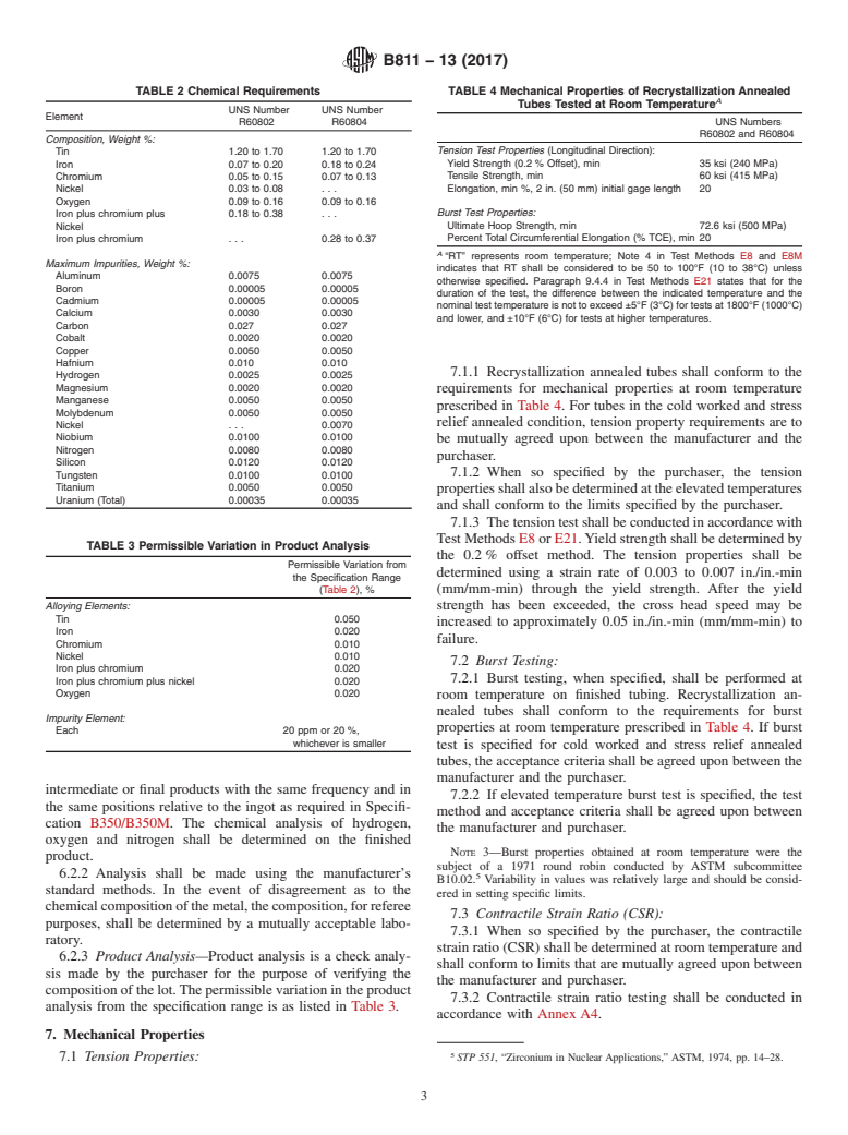


Standards Content (Sample)
NOTICE: This standard has either been superseded and replaced by a new version or withdrawn.
Contact ASTM International (www.astm.org) for the latest information
Designation:B811 −13 (Reapproved 2017)
Standard Specification for
Wrought Zirconium Alloy Seamless Tubes for Nuclear
Reactor Fuel Cladding
This standard is issued under the fixed designation B811; the number immediately following the designation indicates the year of
original adoption or, in the case of revision, the year of last revision.Anumber in parentheses indicates the year of last reapproval.A
superscript epsilon (´) indicates an editorial change since the last revision or reapproval.
1. Scope B350/B350MSpecification for Zirconium and Zirconium
Alloy Ingots for Nuclear Application
1.1 This specification covers seamless wrought zirconium-
B353Specification for Wrought Zirconium and Zirconium
alloy tubes for nuclear fuel cladding application, in the outside
Alloy Seamless and Welded Tubes for Nuclear Service
diameter (OD) size range of 0.200 in. (5.1 mm) to 0.650 in.
(Except Nuclear Fuel Cladding)
(16.5 mm) and wall thickness range of 0.010 in. (0.25 mm) to
E8Test Methods for Tension Testing of Metallic Materials
0.035 in. (0.89 mm).
E8MTestMethodsforTensionTestingofMetallicMaterials
1.2 Two grades of reactor grade zirconium alloys are
[Metric] (Withdrawn 2008)
described.
E21TestMethodsforElevatedTemperatureTensionTestsof
1.2.1 The present UNS numbers designated for the two
Metallic Materials
grades are given in Table 1.
E29Practice for Using Significant Digits in Test Data to
1.3 Unlessasingleunitisused,forexamplecorrosionmass
Determine Conformance with Specifications
gain in mg/dm , the values stated in either inch-pound or SI
E112Test Methods for Determining Average Grain Size
units are to be regarded separately as standard. The values
G2/G2MTest Method for Corrosion Testing of Products of
stated in each system are not exact equivalents; therefore each
Zirconium, Hafnium, and Their Alloys in Water at 680°F
system must be used independently of the other. SI values
(360°C) or in Steam at 750°F (400°C)
cannot be mixed with inch-pound values.
2.2 Other Document:
1.4 The following precautionary caveat pertains only to the
ANSI B46.1Surface Texture (Surface Roughness)
test method portions of this specification: This standard does
not purport to address all of the safety concerns, if any,
3. Terminology
associated with its use. It is the responsibility of the user of this
standard to establish appropriate safety, health, and environ-
3.1 Definitions of Terms Specific to This Standard:
mental practices and determine the applicability of regulatory
3.1.1 dimensions, n—tube dimensions are outside diameter,
limitations prior to use.
inside diameter, and wall thickness. Only two of these param-
1.5 This international standard was developed in accor-
eters may be specified in addition to length, except minimum
dance with internationally recognized principles on standard-
wallmaybespecifiedwithoutsideandinsidediameter.Ineach
ization established in the Decision on Principles for the
case, ovality and wall thickness variation (WTV) may be
Development of International Standards, Guides and Recom-
specified as additional requirements.
mendations issued by the World Trade Organization Technical
Barriers to Trade (TBT) Committee.
3.1.2 hydride orientation fraction, Fn, n—the ratio of hy-
dride platelets oriented in the radial direction to the total
2. Referenced Documents
hydride platelets in the field examined.
2.1 ASTM Standards:
3.1.3 lot size, n—a lot shall consist of all tubes of the same
size,shape,condition,andfinishproducedfromthesameingot
This specification is under the jurisdiction of ASTM Committee B10 on
by the same reduction schedule and heat treatment. The final
Reactive and Refractory Metals and Alloys and is the direct responsibility of
heat treatment shall be in a single furnace charge.
Subcommittee B10.02 on Zirconium and Hafnium.
Current edition approved Nov. 1, 2017. Published November 2017. Originally
ɛ
approved in 1990. Last previous edition approved in 2013 as B811–13 . DOI:
10.1520/B0811-13R17.
2 3
For referenced ASTM standards, visit the ASTM website, www.astm.org, or The last approved version of this historical standard is referenced on
contact ASTM Customer Service at service@astm.org. For Annual Book of ASTM www.astm.org.
Standards volume information, refer to the standard’s Document Summary page on Available from American Iron and Steel Institute (AISI), 1140 Connecticut
the ASTM website. Ave., NW, Suite 705, Washington, DC 20036, http://www.steel.org.
Copyright © ASTM International, 100 Barr Harbor Drive, PO Box C700, West Conshohocken, PA 19428-2959. United States
B811−13 (2017)
TABLE 1 ASTM and UNS Number Designation for Reactor Grade
4.1.9 General test requirements and test plan for lots (see
Zirconium Alloys
Section 10),
Grade UNS Number
4.1.10 Number of tests and resampling plan and require-
Zirconium-tin alloy R60802
ments (see Section 11), and
Zirconium-tin alloy R60804
4.1.11 Certification of test (see Section 16).
NOTE 2—Atypical order description may read as follows: 1500 pieces
of seamless zirconium-alloy fuel clad tubes OD abraded and ID pickled,
3.1.4 mill finish tubes, n—tubes that have received all
Grade R60804, recrystallization annealed 0.650 in. nominal OD by 0.580
finishing operations subsequent to final anneal, which poten-
in. nominal ID by 0.032 in. minimum wall by 10 ft long with a maximum
tially affects tube mechanical, dimensional, or surface condi- OD ovality of 0.004 in. and maximum WTV of 0.005 in. in accordance
withB811–XX.Maximumsurfacefinishtobe50µin.RaODand50µin.
tion. These operations include, but are not limited to, pickling,
Ra ID.
cleaning, outer and inner surface abrasive conditioning, and
4.2 In addition to the information in 4.1, the following
straightening.
points of agreement between the manufacturer and purchaser
3.1.5 ovality, n—the difference between the maximum and
should be specified in the purchase order as required:
minimum diameter, either outer or inner, as determined at any
4.2.1 Method of determining yield strength if other than
one transverse cross-section of the tube.
0.2% offset method (see Section 7),
3.1.6 wall thickness variation (WTV), n—the difference
4.2.2 Initial gage length of mechanical test samples for
between maximum and minimum wall thickness measured at
determining elongation after rupture if other than 2 in. (50
any one transverse cross-section of the tube.
mm),
4.2.3 Mechanical property requirements for tube other than
NOTE1—MeasurementofovalityandWTVmadebyahelicalscanwith
a pitch not exceeding 0.25 in. (6.5 mm) shall be considered as equivalent fully recrystallization annealed (see Section 7),
to “at any one cross-section of the tube.”
4.2.4 Location of the inside diameter plugs in elevated
3.2 Lot Definitions: temperature short-time tension test, when specified (see Sec-
3.2.1 castings, n—alotshallconsistofallcastingsproduced tion 7.1.3),
from the same pour. 4.2.5 Specimen temperature(s) during mechanical testing if
other than room temperature and properties and test require-
3.2.2 ingot, n—no definition required.
ments (see Section 7), and
3.2.3 rounds,flats,tubes,andwroughtpowdermetallurgical
4.2.6 Grain size requirements and specimen heat treatment
products (single definition, common to nuclear and non-
method for stress relief annealed tubes (see Section 8.1),
nuclear standards) , n—a lot shall consist of a material of the
4.2.7 Hydride orientation specimen heat treatment, if
samesize,shape,condition,andfinishproducedfromthesame
required,evaluationmethod,andmagnificationofphotomicro-
ingot or powder blend by the same reduction schedule and the
graph (see Annex A2),
same heat treatment parameters. Unless otherwise agreed
4.2.8 For hydride orientation, angle theta (θ) for determin-
between manufacturer and purchaser, a lot shall be limited to
ing radial platelets (see Section 8.3 and Annex A2).
the product of an 8 h period for final continuous anneal, or to
4.2.9 Burst property acceptance requirements, when speci-
a single furnace load for final batch anneal.
fied (see Section 8.4),
3.2.4 sponge, n—a lot shall consist of a single blend
4.2.10 Use of mandrel and post burst test measurement
produced at one time.
technique (see Annex A1).
4.2.11 Contractile strain ratio acceptance criteria, when
3.2.5 weld fittings, n—definition is to be mutually agreed
specified (see Section 7.3 and Annex A4).
upon between manufacturer and the purchaser.
4. Ordering Information 5. Materials and Manufacture
4.1 Purchase orders for tubes covered in this specification
5.1 Materials covered by this specification shall be pro-
shall include the following information to describe adequately
duced in accordance with Specification B350/B350M; all
the desired material: processes to be done in furnaces usually used for reactive
4.1.1 Quantity,
metals.
4.1.2 Grade (see Table 1),
5.2 Tubes shall be made by a process approved by the
4.1.3 Condition (recrystallization annealed or stress relief
purchaser.
annealed),
4.1.4 Tube dimensions and tolerance,
6. Chemical Composition
4.1.5 ASTM designation and year of issue,
6.1 The tubes shall conform to the requirements for chemi-
4.1.6 Surface texture on (roughness) the inside and outside
cal composition prescribed in Table 2.
surfaces (R (micro-inches or micrometers)),
a
4.1.7 Surface condition on the inside diameter (ID) and 6.2 Chemical Analysis:
outside diameter (OD) surfaces (as pickled, blasted, abraded, 6.2.1 The analysis of the material produced to this specifi-
etc.), cation shall be the one made by the manufacturer on the ingot
4.1.8 Sample test conditions (if other than mill finish in accordance with Specification B350/B350M. This analysis
condition) and standards for corrosion test (see Section 8.2), canbeperformedbythemanufacturerontheingotitself,oron
B811−13 (2017)
TABLE 2 Chemical Requirements TABLE 4 Mechanical Properties of Recrystallization Annealed
A
Tubes Tested at Room Temperature
UNS Number UNS Number
Element
R60802 R60804 UNS Numbers
R60802 and R60804
Composition, Weight %:
Tin 1.20 to 1.70 1.20 to 1.70 Tension Test Properties (Longitudinal Direction):
Yield Strength (0.2 % Offset), min 35 ksi (240 MPa)
Iron 0.07 to 0.20 0.18 to 0.24
Tensile Strength, min 60 ksi (415 MPa)
Chromium 0.05 to 0.15 0.07 to 0.13
Nickel 0.03 to 0.08 . . . Elongation, min %, 2 in. (50 mm) initial gage length 20
Oxygen 0.09 to 0.16 0.09 to 0.16
Iron plus chromium plus 0.18 to 0.38 . . . Burst Test Properties:
Ultimate Hoop Strength, min 72.6 ksi (500 MPa)
Nickel
Iron plus chromium . . . 0.28 to 0.37 Percent Total Circumferential Elongation (% TCE), min 20
A
“RT” represents room temperature; Note 4 in Test Methods E8 and E8M
Maximum Impurities, Weight %:
indicates that RT shall be considered to be 50 to 100°F (10 to 38°C) unless
Aluminum 0.0075 0.0075
otherwise specified. Paragraph 9.4.4 in Test Methods E21 states that for the
Boron 0.00005 0.00005
duration of the test, the difference between the indicated temperature and the
Cadmium 0.00005 0.00005
nominaltesttemperatureisnottoexceed±5°F(3°C)fortestsat1800°F(1000°C)
Calcium 0.0030 0.0030
and lower, and ±10°F (6°C) for tests at higher temperatures.
Carbon 0.027 0.027
Cobalt 0.0020 0.0020
Copper 0.0050 0.0050
Hafnium 0.010 0.010
7.1.1 Recrystallization annealed tubes shall conform to the
Hydrogen 0.0025 0.0025
Magnesium 0.0020 0.0020
requirements for mechanical properties at room temperature
Manganese 0.0050 0.0050
prescribed in Table 4. For tubes in the cold worked and stress
Molybdenum 0.0050 0.0050
relief annealed condition, tension property requirements are to
Nickel . . . 0.0070
Niobium 0.0100 0.0100
be mutually agreed upon between the manufacturer and the
Nitrogen 0.0080 0.0080
purchaser.
Silicon 0.0120 0.0120
7.1.2 When so specified by the purchaser, the tension
Tungsten 0.0100 0.0100
Titanium 0.0050 0.0050
propertiesshallalsobedeterminedattheelevatedtemperatures
Uranium (Total) 0.00035 0.00035
and shall conform to the limits specified by the purchaser.
7.1.3 Thetensiontestshallbeconductedinaccordancewith
TestMethodsE8orE21.Yieldstrengthshallbedeterminedby
TABLE 3 Permissible Variation in Product Analysis
the 0.2% offset method. The tension properties shall be
Permissible Variation from
determined using a strain rate of 0.003 to 0.007 in./in.-min
the Specification Range
(Table 2), % (mm/mm-min) through the yield strength. After the yield
strength has been exceeded, the cross head speed may be
Alloying Elements:
Tin 0.050
increased to approximately 0.05 in./in.-min (mm/mm-min) to
Iron 0.020
failure.
Chromium 0.010
Nickel 0.010
7.2 Burst Testing:
Iron plus chromium 0.020
7.2.1 Burst testing, when specified, shall be performed at
Iron plus chromium plus nickel 0.020
Oxygen 0.020
room temperature on finished tubing. Recrystallization an-
nealed tubes shall conform to the requirements for burst
Impurity Element:
properties at room temperature prescribed in Table 4. If burst
Each 20 ppm or 20 %,
whichever is smaller
test is specified for cold worked and stress relief annealed
tubes, the acceptance criteria shall be agreed upon between the
manufacturer and the purchaser.
intermediate or final products with the same frequency and in
7.2.2 If elevated temperature burst test is specified, the test
the same positions relative to the ingot as required in Specifi-
method and acceptance criteria shall be agreed upon between
cation B350/B350M. The chemical analysis of hydrogen,
the manufacturer and purchaser.
oxygen and nitrogen shall be determined on the finished
NOTE 3—Burst properties obtained at room temperature were the
product.
subject of a 1971 round robin conducted by ASTM subcommittee
6.2.2 Analysis shall be made using the manufacturer’s 5
B10.02. Variability in values was relatively large and should be consid-
standard methods. In the event of disagreement as to the
ered in setting specific limits.
chemicalcompositionofthemetal,thecomposition,forreferee
7.3 Contractile Strain Ratio (CSR):
purposes, shall be determined by a mutually acceptable labo-
7.3.1 When so specified by the purchaser, the contractile
ratory.
strainratio(CSR)shallbedeterminedatroomtemperatureand
6.2.3 Product Analysis—Product analysis is a check analy-
shall conform to limits that are mutually agreed upon between
sis made by the purchaser for the purpose of verifying the
the manufacturer and purchaser.
compositionofthelot.Thepermissiblevariationintheproduct
7.3.2 Contractile strain ratio testing shall be conducted in
analysis from the specification range is as listed in Table 3.
accordance with Annex A4.
7. Mechanical Properties
7.1 Tension Properties: STP 551, “Zirconium in Nuclear Applications,” ASTM, 1974, pp. 14–28.
B811−13 (2017)
NOTE4—Contractilestrainratiotestingwasthesubjectofa1993round
...
This document is not an ASTM standard and is intended only to provide the user of an ASTM standard an indication of what changes have been made to the previous version. Because
it may not be technically possible to adequately depict all changes accurately, ASTM recommends that users consult prior editions as appropriate. In all cases only the current version
of the standard as published by ASTM is to be considered the official document.
´1
Designation: B811 − 13 B811 − 13 (Reapproved 2017)
Standard Specification for
Wrought Zirconium Alloy Seamless Tubes for Nuclear
Reactor Fuel Cladding
This standard is issued under the fixed designation B811; the number immediately following the designation indicates the year of
original adoption or, in the case of revision, the year of last revision. A number in parentheses indicates the year of last reapproval. A
superscript epsilon (´) indicates an editorial change since the last revision or reapproval.
ε NOTE—Equations in Section A4.5 were corrected editorially in August 2014.
1. Scope
1.1 This specification covers seamless wrought zirconium-alloy tubes for nuclear fuel cladding application, in the outside
diameter (OD) size range of 0.200 in. (5.1 mm) to 0.650 in. (16.5 mm) and wall thickness range of 0.010 in. (0.25 mm) to 0.035
in. (0.89 mm).
1.2 Two grades of reactor grade zirconium alloys are described.
1.2.1 The present UNS numbers designated for the two grades are given in Table 1.
1.3 Unless a single unit is used, for example corrosion mass gain in mg/dm , the values stated in either inch-pound or SI units
are to be regarded separately as standard. The values stated in each system are not exact equivalents; therefore each system must
be used independently of the other. SI values cannot be mixed with inch-pound values.
1.4 The following precautionary caveat pertains only to the test method portions of this specification:This standard does not
purport to address all of the safety concerns, if any, associated with its use. It is the responsibility of the user of this standard to
establish appropriate safety safety, health, and healthenvironmental practices and determine the applicability of regulatory
limitations prior to use.
1.5 This international standard was developed in accordance with internationally recognized principles on standardization
established in the Decision on Principles for the Development of International Standards, Guides and Recommendations issued
by the World Trade Organization Technical Barriers to Trade (TBT) Committee.
2. Referenced Documents
2.1 ASTM Standards:
B350/B350M Specification for Zirconium and Zirconium Alloy Ingots for Nuclear Application
B353 Specification for Wrought Zirconium and Zirconium Alloy Seamless and Welded Tubes for Nuclear Service (Except
Nuclear Fuel Cladding)
E8 Test Methods for Tension Testing of Metallic Materials
E8M Test Methods for Tension Testing of Metallic Materials [Metric] (Withdrawn 2008)
E21 Test Methods for Elevated Temperature Tension Tests of Metallic Materials
E29 Practice for Using Significant Digits in Test Data to Determine Conformance with Specifications
E112 Test Methods for Determining Average Grain Size
G2/G2M Test Method for Corrosion Testing of Products of Zirconium, Hafnium, and Their Alloys in Water at 680°F (360°C)
or in Steam at 750°F (400°C)
2.2 Other Document:
ANSI B46.1 Surface Texture (Surface Roughness)
This specification is under the jurisdiction of ASTM Committee B10 on Reactive and Refractory Metals and Alloys and is the direct responsibility of Subcommittee
B10.02 on Zirconium and Hafnium.
Current edition approved May 1, 2013Nov. 1, 2017. Published May 2013November 2017. Originally approved in 1990. Last previous edition approved in 20072013 as
ɛ
B811 – 02 (2007).B811 – 13 . DOI: 10.1520/B0811-13E01.10.1520/B0811-13R17.
For referenced ASTM standards, visit the ASTM website, www.astm.org, or contact ASTM Customer Service at service@astm.org. For Annual Book of ASTM Standards
volume information, refer to the standard’s Document Summary page on the ASTM website.
The last approved version of this historical standard is referenced on www.astm.org.
Available from American Iron and Steel Institute (AISI), 1140 Connecticut Ave., NW, Suite 705, Washington, DC 20036, http://www.steel.org.
Copyright © ASTM International, 100 Barr Harbor Drive, PO Box C700, West Conshohocken, PA 19428-2959. United States
B811 − 13 (2017)
TABLE 1 ASTM and UNS Number Designation for Reactor Grade
Zirconium Alloys
Grade UNS Number
Zirconium-tin alloy R60802
Zirconium-tin alloy R60804
3. Terminology
3.1 Definitions of Terms Specific to This Standard:
3.1.1 dimensions, n—tube dimensions are outside diameter, inside diameter, and wall thickness. Only two of these parameters
may be specified in addition to length, except minimum wall may be specified with outside and inside diameter. In each case,
ovality and wall thickness variation (WTV) may be specified as additional requirements.
3.1.2 hydride orientation fraction, Fn, n—the ratio of hydride platelets oriented in the radial direction to the total hydride
platelets in the field examined.
3.1.3 lot size, n—a lot shall consist of all tubes of the same size, shape, condition, and finish produced from the same ingot by
the same reduction schedule and heat treatment. The final heat treatment shall be in a single furnace charge.
3.1.4 mill finish tubes, n—tubes that have received all finishing operations subsequent to final anneal, which potentially affects
tube mechanical, dimensional, or surface condition. These operations include, but are not limited to, pickling, cleaning, outer and
inner surface abrasive conditioning, and straightening.
3.1.5 ovality, n—the difference between the maximum and minimum diameter, either outer or inner, as determined at any one
transverse cross-section of the tube.
3.1.6 wall thickness variation (WTV), n—the difference between maximum and minimum wall thickness measured at any one
transverse cross-section of the tube.
NOTE 1—Measurement of ovality and WTV made by a helical scan with a pitch not exceeding 0.25 in. (6.5 mm) shall be considered as equivalent to
“at any one cross-section of the tube.”
3.2 Lot Definitions:
3.2.1 castings, n—a lot shall consist of all castings produced from the same pour.
3.2.2 ingot, n—no definition required.
3.2.3 rounds, flats, tubes, and wrought powder metallurgical products (single definition, common to nuclear and non-nuclear
standards) , n—a lot shall consist of a material of the same size, shape, condition, and finish produced from the same ingot or
powder blend by the same reduction schedule and the same heat treatment parameters. Unless otherwise agreed between
manufacturer and purchaser, a lot shall be limited to the product of an 8 h period for final continuous anneal, or to a single furnace
load for final batch anneal.
3.2.4 sponge, n—a lot shall consist of a single blend produced at one time.
3.2.5 weld fittings, n—definition is to be mutually agreed upon between manufacturer and the purchaser.
4. Ordering Information
4.1 Purchase orders for tubes covered in this specification shall include the following information to describe adequately the
desired material:
4.1.1 Quantity,
4.1.2 Grade (see Table 1),
4.1.3 Condition (recrystallization annealed or stress relief annealed),
4.1.4 Tube dimensions and tolerance,
4.1.5 ASTM designation and year of issue,
4.1.6 Surface texture on (roughness) the inside and outside surfaces (R (micro-inches or micrometers)),
a
4.1.7 Surface condition on the inside diameter (ID) and outside diameter (OD) surfaces (as pickled, blasted, abraded, etc.),
4.1.8 Sample test conditions (if other than mill finish condition) and standards for corrosion test (see Section 8.2),
4.1.9 General test requirements and test plan for lots (see Section 10),
4.1.10 Number of tests and resampling plan and requirements (see Section 11), and
4.1.11 Certification of test (see Section 16).
NOTE 2—A typical order description may read as follows: 1500 pieces of seamless zirconium-alloy fuel clad tubes OD abraded and ID pickled, Grade
R60804, recrystallization annealed 0.650 in. nominal OD by 0.580 in. nominal ID by 0.032 in. minimum wall by 10 ft long with a maximum OD ovality
of 0.004 in. and maximum WTV of 0.005 in. in accordance with B811 – XX. Maximum surface finish to be 50 μin. Ra OD and 50 μin. Ra ID.
4.2 In addition to the information in 4.1, the following points of agreement between the manufacturer and purchaser should be
specified in the purchase order as required:
4.2.1 Method of determining yield strength if other than 0.2 % offset method (see Section 7),
B811 − 13 (2017)
4.2.2 Initial gage length of mechanical test samples for determining elongation after rupture if other than 2 in. (50 mm),
4.2.3 Mechanical property requirements for tube other than fully recrystallization annealed (see Section 7),
4.2.4 Location of the inside diameter plugs in elevated temperature short-time tension test, when specified (see Section 7.1.3),
4.2.5 Specimen temperature(s) during mechanical testing if other than room temperature and properties and test requirements
(see Section 7), and
4.2.6 Grain size requirements and specimen heat treatment method for stress relief annealed tubes (see Section 8.1),
4.2.7 Hydride orientation specimen heat treatment, if required, evaluation method, and magnification of photomicrograph (see
Annex A2),
4.2.8 For hydride orientation, angle theta (θ) for determining radial platelets (see Section 8.3 and Annex A2).
4.2.9 Burst property acceptance requirements, when specified (see Section 8.4),
4.2.10 Use of mandrel and post burst test measurement technique (see Annex A1).
4.2.11 Contractile strain ratio acceptance criteria, when specified (see Section 7.3 and Annex A4).
5. Materials and Manufacture
5.1 Materials covered by this specification shall be produced in accordance with Specification B350/B350M; all processes to
be done in furnaces usually used for reactive metals.
5.2 Tubes shall be made by a process approved by the purchaser.
6. Chemical Composition
6.1 The tubes shall conform to the requirements for chemical composition prescribed in Table 2.
6.2 Chemical Analysis:
6.2.1 The analysis of the material produced to this specification shall be the one made by the manufacturer on the ingot in
accordance with Specification B350/B350M. This analysis can be performed by the manufacturer on the ingot itself, or on
intermediate or final products with the same frequency and in the same positions relative to the ingot as required in Specification
B350/B350M. The chemical analysis of hydrogen, oxygen and nitrogen shall be determined on the finished product.
6.2.2 Analysis shall be made using the manufacturer’s standard methods. In the event of disagreement as to the chemical
composition of the metal, the composition, for referee purposes, shall be determined by a mutually acceptable laboratory.
6.2.3 Product Analysis—Product analysis is a check analysis made by the purchaser for the purpose of verifying the composition
of the lot. The permissible variation in the product analysis from the specification range is as listed in Table 3.
7. Mechanical Properties
7.1 Tension Properties:
7.1.1 Recrystallization annealed tubes shall conform to the requirements for mechanical properties at room temperature
prescribed in Table 4. For tubes in the cold worked and stress relief annealed condition, tension property requirements are to be
mutually agreed upon between the manufacturer and the purchaser.
7.1.2 When so specified by the purchaser, the tension properties shall also be determined at the elevated temperatures and shall
conform to the limits specified by the purchaser.
7.1.3 The tension test shall be conducted in accordance with Test Methods E8 or E21. Yield strength shall be determined by
the 0.2 % offset method. The tension properties shall be determined using a strain rate of 0.003 to 0.007 in./in.-min (mm/mm-min)
through the yield strength. After the yield strength has been exceeded, the cross head speed may be increased to approximately
0.05 in./in.-min (mm/mm-min) to failure.
7.2 Burst Testing:
7.2.1 Burst testing, when specified, shall be performed at room temperature on finished tubing. Recrystallization annealed tubes
shall conform to the requirements for burst properties at room temperature prescribed in Table 4. If burst test is specified for cold
worked and stress relief annealed tubes, the acceptance criteria shall be agreed upon between the manufacturer and the purchaser.
7.2.2 If elevated temperature burst test is specified, the test method and acceptance criteria shall be agreed upon between the
manufacturer and purchaser.
NOTE 3—Burst properties obtained at room temperature were the subject of a 1971 round robin conducted by ASTM subcommittee B10.02. Variability
in values was relatively large and should be considered in setting specific limits.
7.3 Contractile Strain Ratio (CSR):
7.3.1 When so specified by the purchaser, the contractile strain ratio (CSR) shall be determined at room temperature and shall
conform to limits that are mutually agreed upon between the manufacturer and purchaser.
7.3.2 Contractile strain ratio testing shall be conducted in accordance with Annex A4.
NOTE 4—Contractile strain ratio testing was the subject of a 1993 round robin conducted by ASTM Subcommittee B10.02 using specimens with
STP 551, “Zirconium in Nuclear Applications,” ASTM, 1974, pp. 14–28.
B811 − 13 (2017)
TABLE 2 Chemical Requirements
UNS Number UNS Number
ElementR60802 R60804
Composition, Weight %:
Tin 1.20 to 1.70 1.20 to 1.70
Tin 1.20 to 1.70 1.20 to 1.70
Iron 0.07 to 0.20 0.18 to 0.24
Iron 0.07 to 0.20 0.18 to 0.24
Chromium 0.05 to 0.15 0.07 to 0.13
Chromium 0.05 to 0.15 0.07 to 0.13
Nickel 0.03 to 0.08 . . .
Nickel 0.03 to 0.08 . . .
Oxygen 0.09 to 0.16 0.09 to 0.16
Oxygen 0.09 to 0.16 0.09 to 0.16
0.18 to 0.38 . . .
Iron plus chromium plus
0.18 to 0.38 . . .
Iron plus chromium plus
Nickel
Nickel
. . . 0.28 to 0.37
Iron plus chromium
. . . 0.28 to 0.37
Iron plus chromium
Maximum Impurities, Weight %:
Aluminum 0.0075 0.0075
Aluminum 0.0075 0.0075
Boron 0.00005 0.00005
Boron 0.00005 0.00005
Cadmium 0.00005 0.00005
Cadmium 0.00005 0.00005
Calcium 0.0030 0.0030
Calcium 0.0030 0.0030
Carbon 0.027 0.027
Carbon 0.027 0.027
Cobalt 0.0020 0.0020
Cobalt 0.0020 0.0020
Copper 0.0050 0.0050
Copper 0.0050 0.0050
Hafnium 0.010 0.010
Hafnium 0.010 0.010
Hydrogen 0.0025 0.0025
Hydrogen 0.0025 0.0025
Magnesium 0.0020 0.0020
Magnesium 0.0020 0.0020
Manganese 0.0050 0.0050
Manganese 0.0050 0.0050
Molybdenum 0.0050 0.0050
Molybdenum 0.0050 0.0050
Nickel . . . 0.0070
Nickel . . . 0.0070
Niobium 0.0100 0.0100
Niobium 0.0100 0.0100
Nitrogen 0.0080 0.0080
Nitrogen 0.0080 0.0080
Silicon 0.0120 0.0120
Silicon 0.0120 0.0120
Tungsten 0.0100 0.010
...
Questions, Comments and Discussion
Ask us and Technical Secretary will try to provide an answer. You can facilitate discussion about the standard in here.