


ASTM E2807-11(2019)
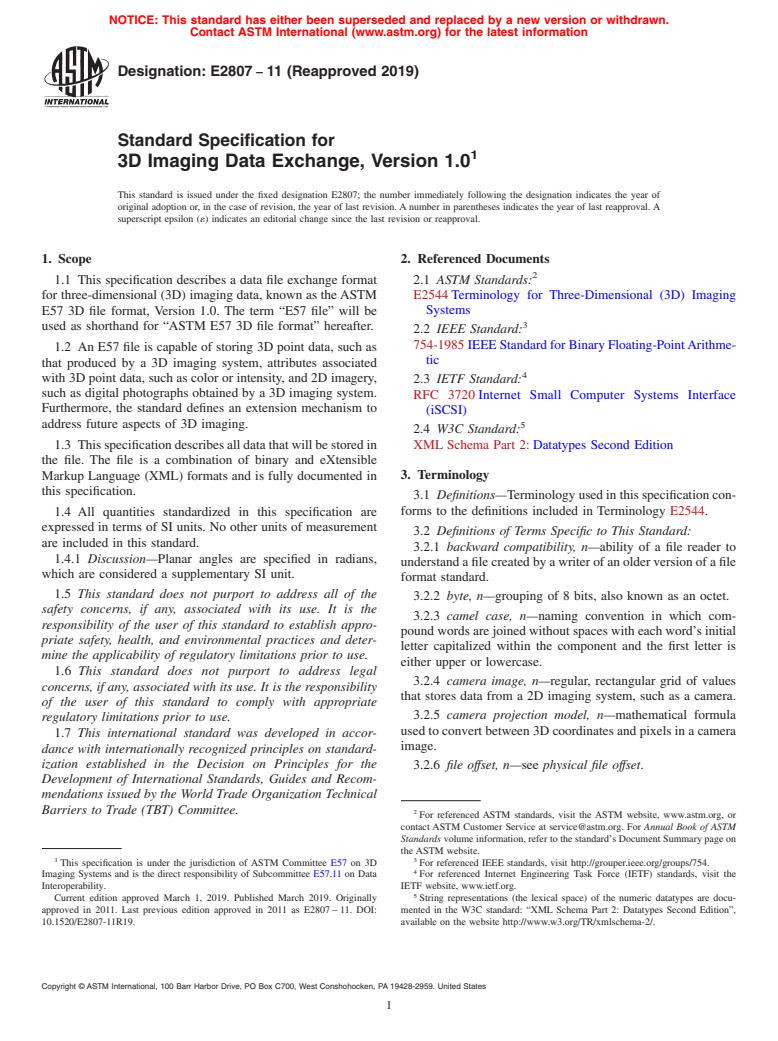
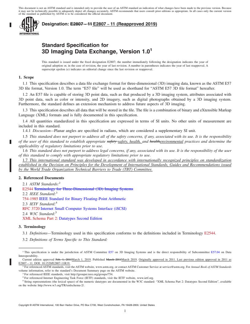
(Specification)Standard Specification for 3D Imaging Data Exchange, Version 1.0
Standard Specification for 3D Imaging Data Exchange, Version 1.0
ABSTRACT
This specification describes a data file exchange format for three-dimensional (3D) imaging data, known as the ASTM E57 3D file format, Version 1.0. In this specification, the term "E57 file" is used as a short version of "ASTM E57 3D file format". An E57 file is capable of storing 3D point data (those produced by 3D imaging systems), attributes associated with 3D point data (color and intensity), and 2D imagery (digital photographs obtained using a 3D imaging system). This specification describes all data that will be stored in the file, which is a combination of binary and eXtensible Markup Language (XML) formats.
SCOPE
1.1 This specification describes a data file exchange format for three-dimensional (3D) imaging data, known as the ASTM E57 3D file format, Version 1.0. The term “E57 file” will be used as shorthand for “ASTM E57 3D file format” hereafter.
1.2 An E57 file is capable of storing 3D point data, such as that produced by a 3D imaging system, attributes associated with 3D point data, such as color or intensity, and 2D imagery, such as digital photographs obtained by a 3D imaging system. Furthermore, the standard defines an extension mechanism to address future aspects of 3D imaging.
1.3 This specification describes all data that will be stored in the file. The file is a combination of binary and eXtensible Markup Language (XML) formats and is fully documented in this specification.
1.4 All quantities standardized in this specification are expressed in terms of SI units. No other units of measurement are included in this standard.
1.4.1 Discussion—Planar angles are specified in radians, which are considered a supplementary SI unit.
1.5 This standard does not purport to address all of the safety concerns, if any, associated with its use. It is the responsibility of the user of this standard to establish appropriate safety, health, and environmental practices and determine the applicability of regulatory limitations prior to use.
1.6 This standard does not purport to address legal concerns, if any, associated with its use. It is the responsibility of the user of this standard to comply with appropriate regulatory limitations prior to use.
1.7 This international standard was developed in accordance with internationally recognized principles on standardization established in the Decision on Principles for the Development of International Standards, Guides and Recommendations issued by the World Trade Organization Technical Barriers to Trade (TBT) Committee.
General Information
Buy Standard
Standards Content (Sample)
NOTICE: This standard has either been superseded and replaced by a new version or withdrawn.
Contact ASTM International (www.astm.org) for the latest information
Designation:E2807 −11 (Reapproved 2019)
Standard Specification for
3D Imaging Data Exchange, Version 1.0
This standard is issued under the fixed designation E2807; the number immediately following the designation indicates the year of
original adoption or, in the case of revision, the year of last revision.Anumber in parentheses indicates the year of last reapproval.A
superscript epsilon (´) indicates an editorial change since the last revision or reapproval.
1. Scope 2. Referenced Documents
1.1 This specification describes a data file exchange format 2.1 ASTM Standards:
for three-dimensional (3D) imaging data, known as theASTM E2544Terminology for Three-Dimensional (3D) Imaging
Systems
E57 3D file format, Version 1.0. The term “E57 file” will be
used as shorthand for “ASTM E57 3D file format” hereafter.
2.2 IEEE Standard:
754-1985IEEEStandardforBinaryFloating-PointArithme-
1.2 An E57 file is capable of storing 3D point data, such as
tic
that produced by a 3D imaging system, attributes associated
with 3D point data, such as color or intensity, and 2D imagery,
2.3 IETF Standard:
such as digital photographs obtained by a 3D imaging system.
RFC 3720 Internet Small Computer Systems Interface
Furthermore, the standard defines an extension mechanism to
(iSCSI)
address future aspects of 3D imaging. 5
2.4 W3C Standard:
XML Schema Part 2:Datatypes Second Edition
1.3 Thisspecificationdescribesalldatathatwillbestoredin
the file. The file is a combination of binary and eXtensible
3. Terminology
Markup Language (XML) formats and is fully documented in
this specification.
3.1 Definitions—Terminologyusedinthisspecificationcon-
forms to the definitions included in Terminology E2544.
1.4 All quantities standardized in this specification are
expressed in terms of SI units. No other units of measurement
3.2 Definitions of Terms Specific to This Standard:
are included in this standard.
3.2.1 backward compatibility, n—ability of a file reader to
1.4.1 Discussion—Planar angles are specified in radians,
understandafilecreatedbyawriterofanolderversionofafile
which are considered a supplementary SI unit.
format standard.
1.5 This standard does not purport to address all of the
3.2.2 byte, n—grouping of 8 bits, also known as an octet.
safety concerns, if any, associated with its use. It is the
3.2.3 camel case, n—naming convention in which com-
responsibility of the user of this standard to establish appro-
poundwordsarejoinedwithoutspaceswitheachword’sinitial
priate safety, health, and environmental practices and deter-
letter capitalized within the component and the first letter is
mine the applicability of regulatory limitations prior to use.
either upper or lowercase.
1.6 This standard does not purport to address legal
3.2.4 camera image, n—regular, rectangular grid of values
concerns, if any, associated with its use. It is the responsibility
that stores data from a 2D imaging system, such as a camera.
of the user of this standard to comply with appropriate
3.2.5 camera projection model, n—mathematical formula
regulatory limitations prior to use.
usedtoconvertbetween3Dcoordinatesandpixelsinacamera
1.7 This international standard was developed in accor-
image.
dance with internationally recognized principles on standard-
ization established in the Decision on Principles for the
3.2.6 file offset, n—see physical file offset.
Development of International Standards, Guides and Recom-
mendations issued by the World Trade Organization Technical
Barriers to Trade (TBT) Committee.
For referenced ASTM standards, visit the ASTM website, www.astm.org, or
contact ASTM Customer Service at service@astm.org. For Annual Book of ASTM
Standards volume information, refer to the standard’s Document Summary page on
the ASTM website.
1 3
This specification is under the jurisdiction of ASTM Committee E57 on 3D For referenced IEEE standards, visit http://grouper.ieee.org/groups/754.
Imaging Systems and is the direct responsibility of Subcommittee E57.11 on Data For referenced Internet Engineering Task Force (IETF) standards, visit the
Interoperability. IETF website, www.ietf.org.
Current edition approved March 1, 2019. Published March 2019. Originally String representations (the lexical space) of the numeric datatypes are docu-
approved in 2011. Last previous edition approved in 2011 as E2807–11. DOI: mented in the W3C standard: “XML Schema Part 2: Datatypes Second Edition”,
10.1520/E2807-11R19. available on the website http://www.w3.org/TR/xmlschema-2/.
Copyright © ASTM International, 100 Barr Harbor Drive, PO Box C700, West Conshohocken, PA 19428-2959. United States
E2807−11 (2019)
3.2.7 file-level coordinate system, n—coordinate system 4.12 W3C—WorldWide Web Consortium
common to all 2D and 3D data sets in a given E57 file.
4.13 XML—eXtensible Markup Language
3.2.8 forward compatibility, n—ability of a file reader to
5. Notation and Mathematical Concepts
read a file that conforms to a newer version of a format
specification than it was designed to read, specifically having
5.1 The following notation and established mathematical
the capability to understand those aspects of the file that were
concepts are used in this specification.
defined in the version it was designed to read, while ignoring
5.2 Intervals:
those portions that were defined in later versions of the format
5.2.1 A closed interval is denoted [a, b], where a ≤ b.A
specification.
closed interval includes the endpoints a and b and all numbers
3.2.9 logical length, n—number of bytes used to describe
inbetween.Anopenintervalisdenoted(a, b),where a≤ b.An
someentityinanE57file,notincludingCRCchecksumbytes.
open interval includes the numbers between the endpoints a
and b, but does not include the endpoints themselves. The
3.2.10 physical file offset, n—numberofbytesprecedingthe
specified byte location in an E57 file, counting payload bytes half-open intervals (a, b] and [a, b) do not include the a and b
and checksums. endpoints, respectively.
3.2.10.1 Discussion—This term is also known as the file
5.3 Cartesian Coordinate System:
offset.
5.3.1 Points in Cartesian coordinates are represented by an
3.2.11 physical length, n—number of bytes used to describe
ordered triplet (x, y, z), where x, y, and z are coordinates along
some entity in an E57 file, including CRC checksum bytes.
the X, Y, and Z axes, respectively. The coordinate system is
right-handed.
3.2.12 record, n—single collection in a sequence of
identically-typed collections of elements.
5.4 Cylindrical Coordinate System:
5.4.1 Points in cylindrical coordinates are represented by an
3.2.13 rigid body transform, n—type of coordinate trans-
ordered triplet (ρ, θ, z), where ρ is the radial distance (in
form that preserves distances between all pairs of points that
meters), θ is the azimuth angle (in radians), and z is the height
furthermore does not admit a reflection.
(in meters).
3.2.13.1 Discussion—A rigid body transform can be used,
5.4.1.1 The azimuth angle is measured as the counterclock-
for example, to convert points from the local coordinates of a
wiserotationofthepositive X-axisaboutthepositive Z-axisof
3D data set (for example, a single laser scan) to a common
a Cartesian reference frame.
coordinate system shared by multiple 3D data sets (for
5.4.2 The following restrictions on cylindrical coordinates
example, a set of laser scans).
are applied:
3.2.14 XML namespace, n—method for qualifying element
ρ$0 (1)
names in XML to prevent the ambiguity of multiple elements
with the same name.
2π,θ# π (2)
3.2.14.1 Discussion—XML namespaces are used in an E57
5.4.3 The conversion from Cartesian to cylindrical coordi-
file to support the definition of extensions.
nates is accomplished through the formulas (note that the z
3.2.15 XML whitespace, n—sequence of one or more of the
coordinate is the same in both systems):
following Unicode characters: the space character (20
2 2
hexadecimal), the carriage return (0D hexadecimal), line feed =
ρ 5 ~x 1y ! (3)
(0A hexadecimal), or tab (09 hexadecimal).
θ 5 atan2 y,x (4)
~ !
3.2.16 zero padding, n—one or more zero-valued bytes
5.4.3.1 The function “atan2(y, x)” is defined as the function
appended to the end of a sequence of bytes.
returning the arc tangent of y/x, in the range (–π,+π] radians.
The signs of the arguments are used to determine the quadrant
4. Acronyms
of the result.
4.1 ASCII—American Standard Code for Information Inter-
5.4.3.2 In degenerate cases, the following convention is
change
observed:
4.2 CRC—Cyclic redundancy check
If x = y = 0, then θ=0.
5.4.4 Conversely, cylindrical coordinates can be converted
4.3 GUID—Globally unique identifier
to Cartesian coordinates using the formulas:
4.4 IEEE—Institute of Electrical and Electronics Engineers
x 5ρ cos θ (5)
~ !
4.5 IETF—Internet Engineering Task Force
y 5ρ sin θ (6)
~ !
4.6 iSCSI—Internet small computer system interface
5.5 Spherical Coordinate System:
4.7 JPEG—Joint Photographic Experts Group
5.5.1 Points in spherical coordinates are represented by an
4.8 PNG—Portable network graphics orderedtriplet(r,θ,φ),where ristherange(inmeters),θisthe
azimuth angle (in radians), and φ is the elevation angle (in
4.9 URI—Uniform resource identifier
radians).
4.10 UTC—Coordinated universal time
5.5.2 Thefollowingrestrictionsonsphericalcoordinatesare
4.11 UTF—Unicode Transformation Format applied:
E2807−11 (2019)
r$0 (7) reflection. A rigid body transform can be represented as a
3 × 3 rotation matrix R and a translation 3-vector t.
2π,θ# π (8)
5.7.2 A3D point is transformed from the source coordinate
π π
system to the destination coordinate system by first applying
2 #φ# (9)
2 2
the rotation and then the translation. More formally, the
transformation operation T(.) of a point p is defined as:
5.5.3 The conversion from spherical to Cartesian coordi-
nates is accomplished through the formulas:
p' 5 T p 5 Rp1t (18)
~ !
x 5 r cos~φ!cos~θ! (10)
The rotation matrix R can be computed from a unit quater-
y 5 r cos φ sin θ (11)
~ ! ~ !
nion q using Eq 17.
5.7.3 Discussion—Rigid body transforms are used in this
z 5 r sin φ (12)
~ !
standard to support the transformation of data represented in a
5.5.4 Conversely, in non-degenerate cases, Cartesian coor-
local coordinate system, such as the coordinate system of a
dinates can be converted to spherical coordinates via the
sensor used to acquire a 3D data set, to a common file-level
formulas:
coordinate system shared by all 3D data sets.
2 2 2
r 5 = x 1y 1z (13)
~ ! 5.8 Trees:
5.8.1 A tree is data structure that represents an acyclic
θ 5 atan2 y,x (14)
~ !
graph.Atree consists of nodes, which store some information,
z
and edges (also known as arcs) that connect the nodes. The
φ 5 arcsin (15)
S D
r
single topmost node is called the root node.Anode may have
5.5.4.1 In degenerate cases, the following conventions are zero or more nodes connected below it, which are called child
observed: nodes. Each node, except the root node, has exactly one node
connectedaboveit,whichiscalledtheparentnode.Nodeswith
If x = y = 0, then θ=0;
no children are called leaf nodes. A descendant is a direct or
If x = y = z = 0, then both θ = 0 and φ=0.
indirect child of a given node.
5.5.5 Discussion—Theelevationismeasuredwithrespectto
5.8.2 Discussion—Trees are used in this standard to de-
the XY-plane, with positive elevations towards the positive
scribe the structure of XML data, as well as index data in
Z-axis. The azimuth is measured as the counterclockwise
binary sections.
rotation of the positive X-axis about the positive Z-axis. This
definition of azimuth follows typical engineering usage. Note
5.9 XML Elements and Attributes:
thatthisdiffersfromtraditionaluseinnavigationorsurveying.
5.9.1 AnXMLelementisthefundamentalbuildingblockof
an XML file. An element consists of a start tag, optional
5.6 Quaternions:
attributes, optional child elements, optional child text, and an
5.6.1 A quaternion is a generalized complex number. A
end tag. Element names in an E57 file are case sensitive.
quaternion, q,isrepresentedbyanorderedfour-tuple(w,x,y,z),
Element names in this specification are written in camel case
where q= w+ xi+ yj+ zk.Thecoordinate wdefinesthescalar
with a lowercase initial character. Type names in this specifi-
part of the quaternion, and the coordinates (x, y, z) define the
cation are written in camel case with an upper case initial
vector part.
character.
5.6.2 The norm of a quaternion, || q ||, is defined as:
5.9.2 Discussion—See Fig. 1 for an excerpt of XML that
2 2 2 2
|| q || 5 =w 1x 1y 1z .
illustrates the parts of an XML element.
5.9.3 XML elements that have child elements form a tree,
5.6.3 Aunit quaternion, q, has the further restriction that its
with each element being a node.
norm || q||=1.
5.9.4 A pathname is a string that specifies the sequence of
5.6.4 Rotationofapointpbyaunitquaternion qisgivenby
elements names that are encountered when traversing from a
the matrix formula:
given origin element to a destination element in an XML tree.
p' 5 Rp (16)
In this standard, pathnames are only defined for destination
elements that are descendants of the origin element.Arelative
where:
pathname is formed by concatenating the sequence of element
2 2 2 2
w 1x 2 y 2 z 2~xy 2 wz! 2~xz1wy!
names traversed using the forward slash (“/”) as a separator.
2 2 2 2
2 xy1wz w 1y 2 x 2 z 2 yz 2 wx
R 5 ~ ! ~ !
Eachsuccessiveelementinthesequenceshallbeachildofthe
F G
2 2 2 2
2 xz 2 wy 2 yz1wx w 1z 2 x 2 y
~ ! ~ !
previous element. Note that the element name of the origin
(17) element does not appear in the pathname. An absolute path-
name has an origin that is the root element of the tree, and is
5.6.5 Discussion—Unitquaternionsareusedinthisstandard
formedbyprependingaforwardslashtotherelativepathname.
to represent rotations in rigid body transforms.
5.9.5 Discussion—As an example, consider a hypothetical
5.7 Rigid Body Transforms:
E57 file consisting of a root element named e57Root which
5.7.1 A rigid body transform converts points from one contains a child element named data3D, which contains a
coordinate reference frame to another, preserving distances child element named0, which contains a child element named
between pairs of points and, furthermore, not admitting a pose, which contains a child element namedtranslation
E2807−11 (2019)
FIG. 1XML Elements and Attributes
, which contains a child element named x. Then the absolute 6.3.3 XML section (required, see Section 8).
pathname of the x element is “/data3D/0/pose/
6.4 Binary portions (including the header and binary sec-
translation/x”, and the relative pathname of the x
tions) of an E57 file are encoded using the little-endian byte
elementrelativetotheposeelementis“translation/x”.
order.
6. General Fil
...
This document is not an ASTM standard and is intended only to provide the user of an ASTM standard an indication of what changes have been made to the previous version. Because
it may not be technically possible to adequately depict all changes accurately, ASTM recommends that users consult prior editions as appropriate. In all cases only the current version
of the standard as published by ASTM is to be considered the official document.
Designation: E2807 − 11 E2807 − 11 (Reapproved 2019)
Standard Specification for
3D Imaging Data Exchange, Version 1.0
This standard is issued under the fixed designation E2807; the number immediately following the designation indicates the year of
original adoption or, in the case of revision, the year of last revision. A number in parentheses indicates the year of last reapproval. A
superscript epsilon (´) indicates an editorial change since the last revision or reapproval.
1. Scope
1.1 This specification describes a data file exchange format for three-dimensional (3D) imaging data, known as the ASTM E57
3D file format, Version 1.0. The term “E57 file” will be used as shorthand for “ASTM E57 3D file format” hereafter.
1.2 An E57 file is capable of storing 3D point data, such as that produced by a 3D imaging system, attributes associated with
3D point data, such as color or intensity, and 2D imagery, such as digital photographs obtained by a 3D imaging system.
Furthermore, the standard defines an extension mechanism to address future aspects of 3D imaging.
1.3 This specification describes all data that will be stored in the file. The file is a combination of binary and eXtensible Markup
Language (XML) formats and is fully documented in this specification.
1.4 All quantities standardized in this specification are expressed in terms of SI units. No other units of measurement are
included in this standard.
1.4.1 Discussion—Planar angles are specified in radians, which are considered a supplementary SI unit.
1.5 This standard does not purport to address all of the safety concerns, if any, associated with its use. It is the responsibility
of the user of this standard to establish appropriate safety safety, health, and healthenvironmental practices and determine the
applicability of regulatory limitations prior to use.
1.6 This standard does not purport to address legal concerns, if any, associated with its use. It is the responsibility of the user
of this standard to comply with appropriate regulatory limitations prior to use.
1.7 This international standard was developed in accordance with internationally recognized principles on standardization
established in the Decision on Principles for the Development of International Standards, Guides and Recommendations issued
by the World Trade Organization Technical Barriers to Trade (TBT) Committee.
2. Referenced Documents
2.1 ASTM Standards:
E2544 Terminology for Three-Dimensional (3D) Imaging Systems
2.2 IEEE Standard:
754-1985 IEEE Standard for Binary Floating-Point Arithmetic
2.3 IETF Standard:
RFC 3720 Internet Small Computer Systems Interface (iSCSI)
2.4 W3C Standard:
XML Schema Part 2: Datatypes Second Edition
3. Terminology
3.1 Definitions—Terminology used in this specification conforms to the definitions included in Terminology E2544.
3.2 Definitions of Terms Specific to This Standard:
This specification is under the jurisdiction of ASTM Committee E57 on 3D Imaging Systems and is the direct responsibility of Subcommittee E57.04 on Data
Interoperability.
Current edition approved Feb. 1, 2011March 1, 2019. Published March 2011March 2019. Originally approved in 2011. Last previous edition approved in 2011 as
E2807 – 11. DOI: 10.1520/E2807-11R19.
For referenced ASTM standards, visit the ASTM website, www.astm.org, or contact ASTM Customer Service at service@astm.org. For Annual Book of ASTM Standards
volume information, refer to the standard’s Document Summary page on the ASTM website.
For referenced IEEE standards, visit http://grouper.ieee.org/groups/754.
For referenced Internet Engineering Task Force (IETF) standards, visit the IETF website, www.ietf.org.
String representations (the lexical space) of the numeric datatypes are documented in the W3C standard: “XML Schema Part 2: Datatypes Second Edition”, available
on the website http://www.w3.org/TR/xmlschema-2/.
Copyright © ASTM International, 100 Barr Harbor Drive, PO Box C700, West Conshohocken, PA 19428-2959. United States
E2807 − 11 (2019)
3.2.1 backward compatibility, n—ability of a file reader to understand a file created by a writer of an older version of a file
format standard.
3.2.2 byte, n—grouping of 8 bits, also known as an octet.
3.2.3 camel case, n—naming convention in which compound words are joined without spaces with each word’s initial letter
capitalized within the component and the first letter is either upper or lowercase.
3.2.4 camera image, n—regular, rectangular grid of values that stores data from a 2D imaging system, such as a camera.
3.2.5 camera projection model, n—mathematical formula used to convert between 3D coordinates and pixels in a camera image.
3.2.6 file offset, n—see physical file offset.
3.2.7 file-level coordinate system, n—coordinate system common to all 2D and 3D data sets in a given E57 file.
3.2.8 forward compatibility, n—ability of a file reader to read a file that conforms to a newer version of a format specification
than it was designed to read, specifically having the capability to understand those aspects of the file that were defined in the
version it was designed to read, while ignoring those portions that were defined in later versions of the format specification.
3.2.9 logical length, n—number of bytes used to describe some entity in an E57 file, not including CRC checksum bytes.
3.2.10 physical file offset, n—number of bytes preceding the specified byte location in an E57 file, counting payload bytes and
checksums.
3.2.10.1 Discussion—
This term is also known as the file offset.
3.2.11 physical length, n—number of bytes used to describe some entity in an E57 file, including CRC checksum bytes.
3.2.12 record, n—single collection in a sequence of identically-typed collections of elements.
3.2.13 rigid body transform, n—type of coordinate transform that preserves distances between all pairs of points that
furthermore does not admit a reflection.
3.2.13.1 Discussion—
A rigid body transform can be used, for example, to convert points from the local coordinates of a 3D data set (for example, a single
laser scan) to a common coordinate system shared by multiple 3D data sets (for example, a set of laser scans).
3.2.14 XML namespace, n—method for qualifying element names in XML to prevent the ambiguity of multiple elements with
the same name.
3.2.14.1 Discussion—
XML namespaces are used in an E57 file to support the definition of extensions.
3.2.15 XML whitespace, n—sequence of one or more of the following Unicode characters: the space character (20 hexadecimal),
the carriage return (0D hexadecimal), line feed (0A hexadecimal), or tab (09 hexadecimal).
3.2.16 zero padding, n—one or more zero-valued bytes appended to the end of a sequence of bytes.
4. Acronyms
4.1 ASCII—American Standard Code for Information Interchange
4.2 CRC—Cyclic redundancy check
4.3 GUID—Globally unique identifier
4.4 IEEE—Institute of Electrical and Electronics Engineers
4.5 IETF—Internet Engineering Task Force
4.6 iSCSI—Internet small computer system interface
4.7 JPEG—Joint Photographic Experts Group
4.8 PNG—Portable network graphics
4.9 URI—Uniform resource identifier
4.10 UTC—Coordinated universal time
4.11 UTF—Unicode Transformation Format
E2807 − 11 (2019)
4.12 W3C—WorldWide Web Consortium
4.13 XML—eXtensible Markup Language
5. Notation and Mathematical Concepts
5.1 The following notation and established mathematical concepts are used in this specification.
5.2 Intervals:
5.2.1 A closed interval is denoted [a,b], where a ≤ b. A closed interval includes the endpoints a and b and all numbers in
between. An open interval is denoted (a,b), where a ≤ b. An open interval includes the numbers between the endpoints a and b,
but does not include the endpoints themselves. The half-open intervals (a,b] and [a,b) do not include the a and b endpoints,
respectively.
5.3 Cartesian Coordinate System:
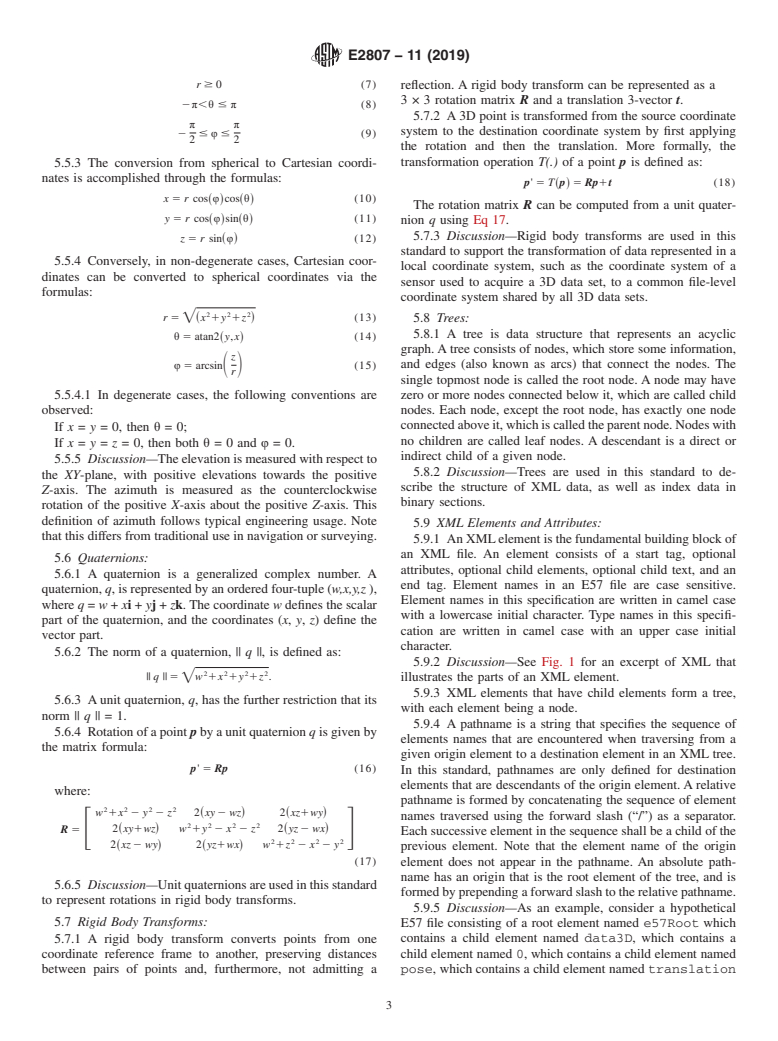
5.3.1 Points in Cartesian coordinates are represented by an ordered triplet (x,y,z), where x, y, and z are coordinates along the
X,Y, and Z axes, respectively. The coordinate system is right-handed.
5.4 Cylindrical Coordinate System:
5.4.1 Points in cylindrical coordinates are represented by an ordered triplet (ρ, θ, z), where ρ is the radial distance (in meters),
θ is the azimuth angle (in radians), and z is the height (in meters).
5.4.1.1 The azimuth angle is measured as the counterclockwise rotation of the positive X-axis about the positive Z-axis of a
Cartesian reference frame.
5.4.2 The following restrictions on cylindrical coordinates are applied:
ρ$0 (1)
2π,θ#π (2)
5.4.3 The conversion from Cartesian to cylindrical coordinates is accomplished through the formulas (note that the z coordinate
is the same in both systems):
2 2
ρ5=~x 1y ! (3)
θ5 atan2 y,x (4)
~ !
5.4.3.1 The function “atan2(y,x)” is defined as the function returning the arc tangent of y/x, in the range (–π, +π] radians. The
signs of the arguments are used to determine the quadrant of the result.
5.4.3.2 In degenerate cases, the following convention is observed:
If x = y = 0, then θ = 0.
5.4.4 Conversely, cylindrical coordinates can be converted to Cartesian coordinates using the formulas:
x 5 ρ cos θ (5)
~ !
y 5 ρ sin~θ! (6)
5.5 Spherical Coordinate System:
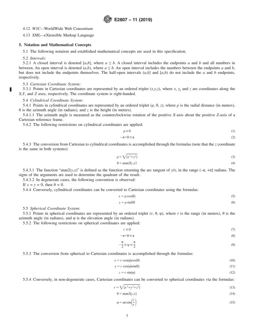
5.5.1 Points in spherical coordinates are represented by an ordered triplet (r, θ, φ), where r is the range (in meters), θ is the
azimuth angle (in radians), and φ is the elevation angle (in radians).
5.5.2 The following restrictions on spherical coordinates are applied:
r $ 0 (7)
2π,θ#π (8)
π π
2 # φ# (9)
2 2
5.5.3 The conversion from spherical to Cartesian coordinates is accomplished through the formulas:
x 5 r cos~φ!cos~θ! (10)
y 5 r cos φ sin θ (11)
~ ! ~ !
z 5 r sin φ (12)
~ !
5.5.4 Conversely, in non-degenerate cases, Cartesian coordinates can be converted to spherical coordinates via the formulas:
2 2 2
r 5= x 1y 1z (13)
~ !
θ5 atan2~y,x! (14)
z
φ5 arcsin (15)
S D
r
E2807 − 11 (2019)
5.5.4.1 In degenerate cases, the following conventions are observed:
If x = y = 0, then θ = 0;
If x = y = z = 0, then both θ = 0 and φ = 0.
5.5.5 Discussion—The elevation is measured with respect to the XY-plane, with positive elevations towards the positive Z-axis.
The azimuth is measured as the counterclockwise rotation of the positive X-axis about the positive Z-axis. This definition of
azimuth follows typical engineering usage. Note that this differs from traditional use in navigation or surveying.
5.6 Quaternions:
5.6.1 A quaternion is a generalized complex number. A quaternion, q, is represented by an ordered four-tuple (w,x,y,z ), where
q = w + xi + yj + zk. The coordinate w defines the scalar part of the quaternion, and the coordinates (x,y,z) define the vector part.
5.6.2 The norm of a quaternion, || q ||, is defined as:
2 2 2 2
|| q || 5=w 1x 1y 1z .
5.6.3 A unit quaternion, q, has the further restriction that its norm || q || = 1.
5.6.4 Rotation of a point p by a unit quaternion q is given by the matrix formula:
p'5 Rp (16)
where:
2 2 2 2
w 1x 2 y 2 z 2~xy 2 wz! 2~xz1wy!
2 2 2 2
2~xy1wz! w 1y 2 x 2 z 2~yz 2 wx!
R 5 (17)
F G
2 2 2 2
2~xz 2 wy! 2~yz1wx! w 1z 2 x 2 y
5.6.5 Discussion—Unit quaternions are used in this standard to represent rotations in rigid body transforms.
5.7 Rigid Body Transforms:
5.7.1 A rigid body transform converts points from one coordinate reference frame to another, preserving distances between pairs
of points and, furthermore, not admitting a reflection. A rigid body transform can be represented as a
3 × 3 rotation matrix R and a translation 3-vector t.
5.7.2 A 3D point is transformed from the source coordinate system to the destination coordinate system by first applying the
rotation and then the translation. More formally, the transformation operation T(.) of a point p is defined as:
p'5 T~p! 5Rp1t (18)
The rotation matrix R can be computed from a unit quaternion q using Eq 17.
5.7.3 Discussion—Rigid body transforms are used in this standard to support the transformation of data represented in a local
coordinate system, such as the coordinate system of a sensor used to acquire a 3D data set, to a common file-level coordinate
system shared by all 3D data sets.
5.8 Trees:
5.8.1 A tree is data structure that represents an acyclic graph. A tree consists of nodes, which store some information, and edges
(also known as arcs) that connect the nodes. The single topmost node is called the root node. A node may have zero or more nodes
connected below it, which are called child nodes. Each node, except the root node, has exactly one node connected above it, which
is called the parent node. Nodes with no children are called leaf nodes. A descendant is a direct or indirect child of a given node.
5.8.2 Discussion—Trees are used in this standard to describe the structure of XML data, as well as index data in binary sections.
5.9 XML Elements and Attributes : Attributes:
5.9.1 An XML element is the fundamental building block of an XML file. An element consists of a start tag, optional attributes,
optional child elements, optional child text, and an end tag. Element names in an E57 file are case sensitive. Element names in
this specification are written in camel case with a lowercase initial character. Type names in this specification are written in camel
case with an upper case initial character.
5.9.2 Discussion—See Fig. 1 for an excerpt of XML that illustrates the parts of an XML element.
5.9.3 XML elements that have child elements form a tree, with each element being a node.
5.9.4 A pathname is a string that specifies the sequence of elements names that are encountered when traversing from a given
origin element to a destination element in an XML tree. In this standard, pathnames are only defined for destination elements that
are descendants of the origin element. A relative pathname is formed by concatenating the sequence of element names traversed
using the forward slash (“/”) as a separator. Each successive element in the sequence shall be a child of the previous element. Note
that the element name of the origin element does not appear in the pathname. An absolute pathname has an origin that is the root
element of the tree, and is formed by prepending a forward slash to the relative pathname.
5.9.5 Discussion—As an example, consider a hypothetical E57 file consisting of a root element named e57Root which
contains a child element nameddata3D, which contains a child element named0, which contains a child element
...
Questions, Comments and Discussion
Ask us and Technical Secretary will try to provide an answer. You can facilitate discussion about the standard in here.