


ASTM F2125-09(2021)
(Test Method)Standard Test Method for Treestand Static Stability and Adherence (Withdrawn 2022)
Standard Test Method for Treestand Static Stability and Adherence (Withdrawn 2022)
SIGNIFICANCE AND USE
4.1 This test method is intended for quality assurance and production control purposes. This test method is not intended to be an independent material or product-acceptance test.
SCOPE
1.1 This test method covers the determination of the static stability and adherence of treestands relative to the manufacturer's rated capacity.
1.2 The values stated in inch-pound units are to be regarded as standard. The values given in parentheses are mathematical conversions to SI units that are provided for information only and are not considered standard.
1.3 This standard does not purport to address all of the safety concerns, if any, associated with its use. It is the responsibility of the user of this standard to establish appropriate safety, health, and environmental practices and determine the applicability of regulatory limitations prior to use.
1.4 This international standard was developed in accordance with internationally recognized principles on standardization established in the Decision on Principles for the Development of International Standards, Guides and Recommendations issued by the World Trade Organization Technical Barriers to Trade (TBT) Committee.
WITHDRAWN RATIONALE
This test method covers the determination of the static stability and adherence of treestands relative to the manufacturer's rated capacity.
Formerly under the jurisdiction of Committee F08 on Sports Equipment, Playing Surfaces, and Facilities, this test method was withdrawn in November 2022 and replaced by Test Method F3545 on the Static Loading of Treestands, Climbing Sticks, and Tripod or Tower Stands.1
General Information
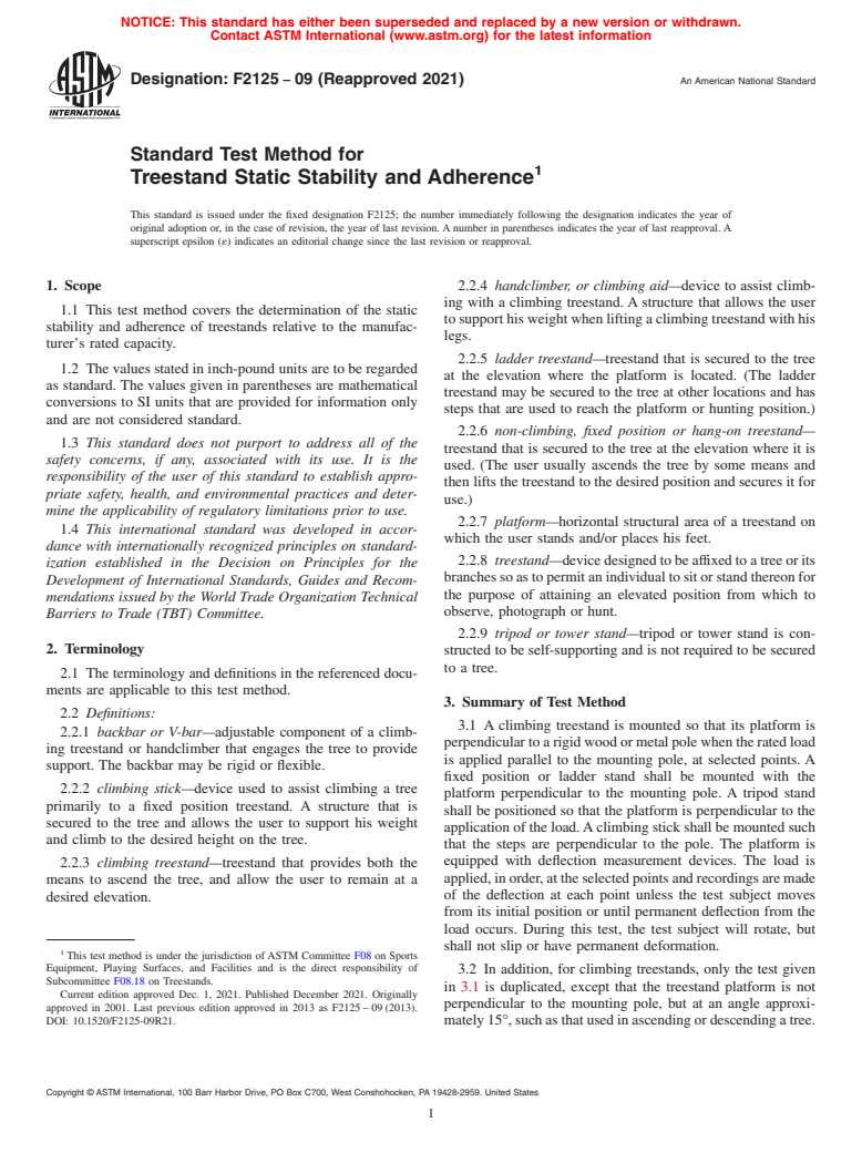
Standards Content (Sample)
NOTICE: This standard has either been superseded and replaced by a new version or withdrawn.
Contact ASTM International (www.astm.org) for the latest information
Designation: F2125 − 09 (Reapproved 2021) An American National Standard
Standard Test Method for
Treestand Static Stability and Adherence
This standard is issued under the fixed designation F2125; the number immediately following the designation indicates the year of
original adoption or, in the case of revision, the year of last revision. A number in parentheses indicates the year of last reapproval. A
superscript epsilon (´) indicates an editorial change since the last revision or reapproval.
1. Scope 2.2.4 handclimber, or climbing aid—device to assist climb-
ing with a climbing treestand. A structure that allows the user
1.1 This test method covers the determination of the static
to support his weight when lifting a climbing treestand with his
stability and adherence of treestands relative to the manufac-
legs.
turer’s rated capacity.
2.2.5 ladder treestand—treestand that is secured to the tree
1.2 The values stated in inch-pound units are to be regarded
at the elevation where the platform is located. (The ladder
as standard. The values given in parentheses are mathematical
treestand may be secured to the tree at other locations and has
conversions to SI units that are provided for information only
steps that are used to reach the platform or hunting position.)
and are not considered standard.
2.2.6 non-climbing, fixed position or hang-on treestand—
1.3 This standard does not purport to address all of the
treestand that is secured to the tree at the elevation where it is
safety concerns, if any, associated with its use. It is the
used. (The user usually ascends the tree by some means and
responsibility of the user of this standard to establish appro-
then lifts the treestand to the desired position and secures it for
priate safety, health, and environmental practices and deter-
use.)
mine the applicability of regulatory limitations prior to use.
2.2.7 platform—horizontal structural area of a treestand on
1.4 This international standard was developed in accor-
which the user stands and/or places his feet.
dance with internationally recognized principles on standard-
2.2.8 treestand—devicedesignedtobeaffixedto a tree or its
ization established in the Decision on Principles for the
branchessoastopermitanindividualtositorstandthereonfor
Development of International Standards, Guides and Recom-
the purpose of attaining an elevated position from which to
mendations issued by the World Trade Organization Technical
observe, photograph or hunt.
Barriers to Trade (TBT) Committee.
2.2.9 tripod or tower stand—tripod or tower stand is con-
2. Terminology
structed to be self-supporting and is not required to be secured
to a tree.
2.1 The terminology and definitions in the referenced docu-
ments are applicable to this test method.
3. Summary of Test Method
2.2 Definitions:
3.1 A climbing treestand is mounted so that its platform is
2.2.1 backbar or V-bar—adjustable component of a climb-
perpendiculartoarigidwoodormetalpolewhentheratedload
ing treestand or handclimber that engages the tree to provide
is applied parallel to the mounting pole, at selected points. A
support. The backbar may be rigid or flexible.
fixed position or ladder stand shall be mounted with the
2.2.2 climbing stick—device used to assist climbing a tree
platform perpendicular to the mounting pole. A tripod stand
primarily to a fixed position treestand. A structure that is
shall be positioned so that the platform is perpendicular to the
secured to the tree and allows the user to support his weight
application of the load.Aclimbing stick shall be mounted such
and climb to the desired height on the tree.
that the steps are perpendicular to the pole. The platform is
equipped with deflection measurement devices. The load is
2.2.3 climbing treestand—treestand that provides both the
applied,inorder,attheselectedpointsandrecordingsaremade
means to ascend the tree, and allow the user to remain at a
of the deflection at each point unless the test subject moves
desired elevation.
from its initial position or until permanent deflection from the
load occurs. During this test, the test subject will rotate, but
shall not slip or have permanent deformation.
This test method is under the jurisdiction of ASTM Committee F08 on Sports
Equipment, Playing Surfaces, and Facilities and is the direct responsibility of
3.2 In addition, for climbing treestands, only the test given
Subcommittee F08.18 on Treestands.
in 3.1 is duplicated, except that the treestand platform is not
Current edition approved Dec. 1, 2021. Published December 2021. Originally
perpendicular to the mounting pole, but at an angle approxi-
approved in 2001. Last previous edition approved in 2013 as F2125 – 09 (2013).
DOI: 10.1520/F2125-09R21. mately15°,suchasthatusedinascendingordescendingatree.
Copyright © ASTM International, 100 Barr Harbor Drive, PO Box C700, West Conshohocken, PA 19428-2959. United States
F2125 − 09 (2021)
4. Significance and Use the surface of the load plate contacting the test subject to
reduce scratching and improve friction.
4.1 This test method is intended for quality assurance and
production control purposes. This test method is not intended
NOTE 1—Load attachment structure must be secured to this load plate
therefore fabrication by welding must assure that the plate remain flat and
to be an independent material or product-acceptance test.
free of distortion.
5.4.3 The load plate shall be positioned on the test subject
5. Apparatus
with its long axis and its center as close to the point as given
5.1 Arigid round wood or metal pole, preferably vertical, is
2 2
in 5.3.1 as possible, yet maintaining the 50 in. (0.032 m )
used to mount the subject product such that pole deflection is
contact area. The centerline of the load plate need not be
minimized.
parallel to the major axis (axis of symmetry) of the test subject.
5.1.1 The mounting pole diameter shall be 10 6 1 in. (254
5.5 Climbing stands are to be tested at approximately 15°
6 25.4 mm).
below level, and above level, as per manufacturer’s directions.
5.2 The load shall be applied using either calibrated weights
5.5.1 Apparatus shall be as given in 5.1 through 5.3.1.2.
or a mechanical device in conjunction with a calibrated load
5.5.2 The load shall be applied as given in 5.4.2 except that
cell. 2 2 2
the load plate shall be 100 in. (0.065 m ) by using a 10 in.
5.2.1 The use of calibrated weights requires that weight 2
(254 mm)by ⁄2 in. (12.7 mm) thick plate.
placement be accurate to assure that the load application
centroid is coincident with the boundaries defined and meets
6. Procedure
the requirements as given in 5.3.1 and in 5.4.3. Caution should
6.1 Read instructions accompanying the test subject to
be exercised for operator protection with the use of weights in
ascertaintheproperprocedureforuseandmountingandsecure
case of slippage or premature failure.
the test subject to the mounting pole such that the platform
5.2.2 The use of a mechanical device such as a tensile
(plane of the platform) is approximately perpendicular to the
testing machine or hydraulic power, in combination with
mounting pole when its rated load is applied. If necessary, use
pulleys, fulcrums or bearings to re-direct forces, requires the
minimum auxiliary temporary means to maintain the subject in
use of a calibrated load cell attached adjacent to the test subject
the correct position during set-up. (Frictional forces, without a
to account for friction losses.
load on the subject, may not be sufficient in some cases for the
5.3 Calibrated deflection measuring devices (such as dial
subject to remain in position. A small band on the mounting
indicators or optical laser) shall be used to measure movement
pole may be necessary).
of the test subject under load. The accuracy of the measuring
6.2 By geometric me
...
Questions, Comments and Discussion
Ask us and Technical Secretary will try to provide an answer. You can facilitate discussion about the standard in here.