


ASTM B230/B230M-07(2021)
(Specification)Standard Specification for Aluminum 1350–H19 Wire for Electrical Purposes
Standard Specification for Aluminum 1350–H19 Wire for Electrical Purposes
ABSTRACT
This specification covers the standard requirements for aluminum 1350-H19, extra hard, round wire for electrical purposes. The aluminum wire shall be made from drawing stock and shall be free of brittleness as evidenced by its ability to be coiled or looped around its own diameter with or without a mandrel. Joints may also be made during the final drawing or in the finished wire by electric-butt welding, cold-pressure welding, or electric-butt, cold-upset welding. Tension tests shall be performed; wherein, the wire shall conform to the tensile strength, elongation, and bending specifications. The specimen shall also conform to the electrical resistivity requirements.
SCOPE
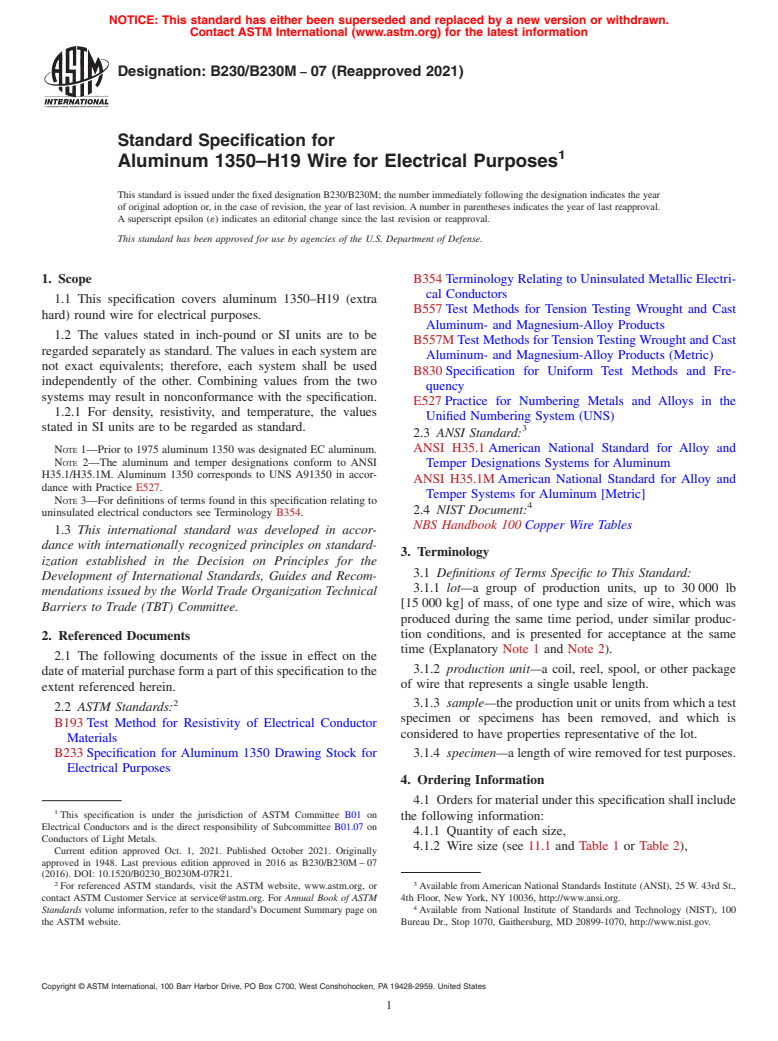
1.1 This specification covers aluminum 1350–H19 (extra hard) round wire for electrical purposes.
1.2 The values stated in inch-pound or SI units are to be regarded separately as standard. The values in each system are not exact equivalents; therefore, each system shall be used independently of the other. Combining values from the two systems may result in nonconformance with the specification.
1.2.1 For density, resistivity, and temperature, the values stated in SI units are to be regarded as standard.
Note 1: Prior to 1975 aluminum 1350 was designated EC aluminum.
Note 2: The aluminum and temper designations conform to ANSI H35.1/H35.1M. Aluminum 1350 corresponds to UNS A91350 in accordance with Practice E527.
Note 3: For definitions of terms found in this specification relating to uninsulated electrical conductors see Terminology B354.
1.3 This international standard was developed in accordance with internationally recognized principles on standardization established in the Decision on Principles for the Development of International Standards, Guides and Recommendations issued by the World Trade Organization Technical Barriers to Trade (TBT) Committee.
General Information
Buy Standard
Standards Content (Sample)
NOTICE: This standard has either been superseded and replaced by a new version or withdrawn.
Contact ASTM International (www.astm.org) for the latest information
Designation:B230/B230M −07 (Reapproved 2021)
Standard Specification for
Aluminum 1350–H19 Wire for Electrical Purposes
This standard is issued under the fixed designation B230/B230M; the number immediately following the designation indicates the year
of original adoption or, in the case of revision, the year of last revision. A number in parentheses indicates the year of last reapproval.
A superscript epsilon (´) indicates an editorial change since the last revision or reapproval.
This standard has been approved for use by agencies of the U.S. Department of Defense.
1. Scope B354 Terminology Relating to Uninsulated Metallic Electri-
cal Conductors
1.1 This specification covers aluminum 1350–H19 (extra
B557 Test Methods for Tension Testing Wrought and Cast
hard) round wire for electrical purposes.
Aluminum- and Magnesium-Alloy Products
1.2 The values stated in inch-pound or SI units are to be
B557M Test Methods for Tension Testing Wrought and Cast
regarded separately as standard. The values in each system are
Aluminum- and Magnesium-Alloy Products (Metric)
not exact equivalents; therefore, each system shall be used
B830 Specification for Uniform Test Methods and Fre-
independently of the other. Combining values from the two
quency
systems may result in nonconformance with the specification.
E527 Practice for Numbering Metals and Alloys in the
1.2.1 For density, resistivity, and temperature, the values
Unified Numbering System (UNS)
stated in SI units are to be regarded as standard. 3
2.3 ANSI Standard:
ANSI H35.1 American National Standard for Alloy and
NOTE 1—Prior to 1975 aluminum 1350 was designated EC aluminum.
NOTE 2—The aluminum and temper designations conform to ANSI
Temper Designations Systems for Aluminum
H35.1/H35.1M. Aluminum 1350 corresponds to UNS A91350 in accor-
ANSI H35.1M American National Standard for Alloy and
dance with Practice E527.
Temper Systems for Aluminum [Metric]
NOTE 3—For definitions of terms found in this specification relating to
2.4 NIST Document:
uninsulated electrical conductors see Terminology B354.
NBS Handbook 100 Copper Wire Tables
1.3 This international standard was developed in accor-
dance with internationally recognized principles on standard-
3. Terminology
ization established in the Decision on Principles for the
3.1 Definitions of Terms Specific to This Standard:
Development of International Standards, Guides and Recom-
3.1.1 lot—a group of production units, up to 30 000 lb
mendations issued by the World Trade Organization Technical
[15 000 kg] of mass, of one type and size of wire, which was
Barriers to Trade (TBT) Committee.
produced during the same time period, under similar produc-
tion conditions, and is presented for acceptance at the same
2. Referenced Documents
time (Explanatory Note 1 and Note 2).
2.1 The following documents of the issue in effect on the
3.1.2 production unit—a coil, reel, spool, or other package
date of material purchase form a part of this specification to the
of wire that represents a single usable length.
extent referenced herein.
3.1.3 sample—the production unit or units from which a test
2.2 ASTM Standards:
specimen or specimens has been removed, and which is
B193 Test Method for Resistivity of Electrical Conductor
considered to have properties representative of the lot.
Materials
B233 Specification for Aluminum 1350 Drawing Stock for 3.1.4 specimen—a length of wire removed for test purposes.
Electrical Purposes
4. Ordering Information
4.1 Orders for material under this specification shall include
This specification is under the jurisdiction of ASTM Committee B01 on
the following information:
Electrical Conductors and is the direct responsibility of Subcommittee B01.07 on
4.1.1 Quantity of each size,
Conductors of Light Metals.
4.1.2 Wire size (see 11.1 and Table 1 or Table 2),
Current edition approved Oct. 1, 2021. Published October 2021. Originally
approved in 1948. Last previous edition approved in 2016 as B230/B230M – 07
(2016). DOI: 10.1520/B0230_B0230M-07R21.
2 3
For referenced ASTM standards, visit the ASTM website, www.astm.org, or Available from American National Standards Institute (ANSI), 25 W. 43rd St.,
contact ASTM Customer Service at service@astm.org. For Annual Book of ASTM 4th Floor, New York, NY 10036, http://www.ansi.org.
Standards volume information, refer to the standard’s Document Summary page on Available from National Institute of Standards and Technology (NIST), 100
the ASTM website. Bureau Dr., Stop 1070, Gaithersburg, MD 20899-1070, http://www.nist.gov.
Copyright © ASTM International, 100 Barr Harbor Drive, PO Box C700, West Conshohocken, PA 19428-2959. United States
B230/B230M−07 (2021)
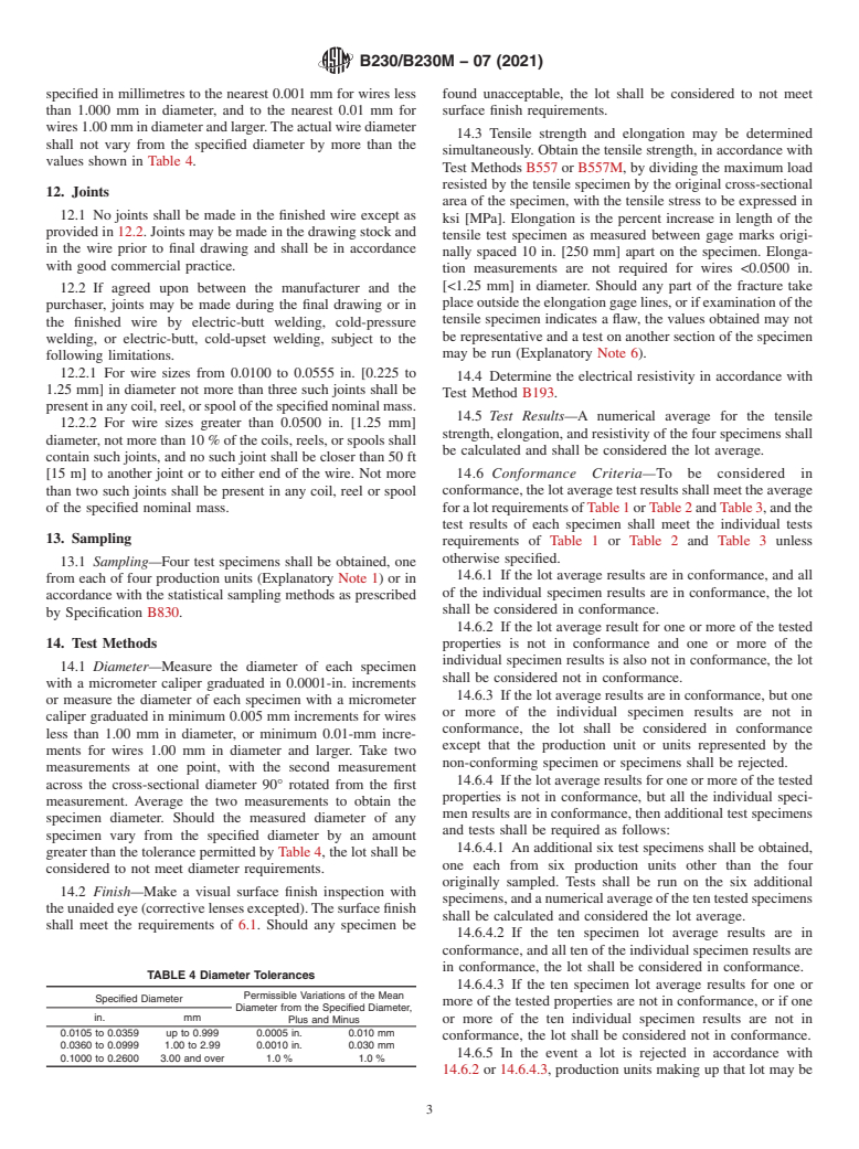
TABLE 1 Tensile Strength and Elongation Requirements
4.1.8 Special package marking, if required (see 16.4).
Elongation in 10 in., min
Tensile Strength, min ksi
(%) 5. Materials and Manufacture
Diameter, in.
Average for Individual Average for Individual
5.1 The aluminum wire shall be made from drawing stock
A
a Lot Tests a Lot Tests
meeting the requirements of Specification B233.
0.0105 to 0.0500 25.0 23.0 . . . . . .
0.0501 to 0.0600 29.0 27.0 1.4 1.2
6. Workmanship, Finish, and Appearance
0.0601 to 0.0700 28.5 27.0 1.5 1.3
0.0701 to 0.0800 28.0 26.5 1.6 1.4
6.1 The wire shall be free of imperfections not consistent
0.0801 to 0.0900 27.5 26.0 1.6 1.5
with good commercial practice.
0.0901 to 0.1000 27.0 25.5 1.6 1.5
0.1001 to 0.1100 26.0 24.5 1.6 1.5
0.1101 to 0.1200 25.5 24.0 1.7 1.6
7. Tensile Properties
0.1201 to 0.1400 25.0 23.5 1.8 1.7
0.1401 to 0.1500 24.5 23.5 1.9 1.8 7.1 Tensile Strength and Elongation—The wire shall con-
0.1501 to 0.1800 24.0 23.0 2.0 1.9
form to the tensile strength and elongation requirements set
0.1801 to 0.2100 24.0 23.0 2.1 2.0
forth in Table 1 or Table 2 (Explanatory Note 3).
0.2101 to 0.2600 23.5 22.5 2.3 2.2
A
For wire diameters within 0.0501 to 0.2600 in., the minimum average tensile
7.2 When requested by the purchaser, tension tests shall be
strength for a lot may be estimated from the following logarithmic equation for
made of specimens of wire containing joints made in the
process control purposes to meet the requirements of this specification: Tensile
drawing stock or in the wire prior to final drawing. Such tests
strength,ksi=17.40–3.84×ln(diameterofwire,in.).Requirementsstatedinthe
table are to be used for all other purposes.
shall indicate tensile strengths not less than 90 % of the values
for individual tests shown in Table 1 or Table 2.
7.3 When requested by the purchaser, tension tests of
TABLE 2 Tensile Strength and Elongation Requirements
specimens containing joints in the finished wire, or in the final
Elongation in 250 mm, min
Tensile Strength, min MPa
drawing, if permitted, shall be made. Such tests shall indicate
(%)
Diameter, mm
tensile strengths to be not less than 11.0 ksi [145 MPa] for
Average for Individual Average for Individual
A
a Lot Tests a Lot Tests
electric-butt welded joints, and not less than 21.0 ksi [75 MPa]
0.227 to 1.25 170.0 160.0 . . . . . . for cold-pressure welded joints and electric-butt, cold-upset
1.26 to 1.50 200.0 185.0 1.4 1.2
welded joints.
1.51 to 1.75 195.0 185.0 1.5 1.3
1.76 to 2.00 195.0 185.0 1.6 1.4
8. Bending Properties
2.01 to 2.25 190.0 180.0 1.6 1.5
2.26 to 2.50 185.0 175.0 1.6 1.5
8.1 The wire shall be free of brittleness as evidenced by its
2.51 to 2.75 180.0 170.0 1.6 1.5
ability to be coiled or looped around its own diameter with or
2.76 to 3.00 175.0 165.0 1.7 1.6
3.01 to 3.50 170.0 160.0 1.8 1.7
without a mandrel. No fracture shall occur. Slight surface
3.51 to 3.75 170.0 160.0 1.9 1.8
checks shall not constitute cause for rejection.
3.76 to 4.50 165.0 160.0 2.0 1.9
4.51 to 5.25 165.0 160.0 2.1 2.0
9. Resistivity
5.26 to 6.50 160.0 155.0 2.3 2.2
A
Forwirediameterswithin1.26to6.50mmtheminimumaveragetensilestrength
9.1 The electrical resistivity shall not exceed the values
for a lot may be estimated from the following logarithmic equation for process
shown in Table 3 (Explanatory Note 4).
control purposes to meet the requirements of this specification: Tensile Strength,
MPa = 205.88 – 27.14 × ln (diameter of wire, mm). Requirements stated in the
10. Density
table are to be used for all other purposes.
10.1 For the purpose of calculating linear density, cross
section, and so forth, the density of aluminum 1350 shall be
3 3
4.1.3 Special tension test, if required (see 7.2 and 7.3), taken as 2705 kg/m [0.0975 lb/in. ] at 20 °C [68 °F].
4.1.4 Frequency of bending test (see 8.1 and 14.5),
11. Diameter
4.1.5 Special jointing procedures, if permitted (see 12.2),
4.1.6 Place of inspection (see 15.2), 11.1 The diameter of the wire shall be specified in inches to
4.1.7 Package size and type (see 16.1), and the nearest 0.0001 in. or the diameter of the wire shall be
A
TABLE 3 Electrical Resistivity Requirements at 20°C [68°F] and Equivalent Copper Resistivity
NOTE 1—The values in boldface are standard; other values are for information only.
Volume
Electrical Resistivity
Conductivity
Volume Mass
%IACS
2 2 2
Ω·mm /m µΩin. µΩ·cm Ω·cmil/ft Ω·lb/mile Ω·g/m
Average for lot 61.2 0.028172 1.1091 2.8172 16.946 434.81 0.076149
Individual tests 61.0 0.028265 1.1128 2.8265 17.002 436.23 0.076399
Copper equivalent 100.0 0.017241 0.67879 1.7241 10.371 875.20 0.15328
A 2
Theequivalentresistivityvaluesfor100%IACSconductivitywereeachcomputedfromthefundamentalIECvalue( ⁄58Ω·mm /m)usingconversionfactorseachaccurate
to at least seven significant figures. Corresponding values for aluminum conductivities were derived from these by multiplying by the reciprocal of the conductivity ratios
and, where applicable, also by the density ratios, both accurate to at least seven significant figures.
B230/B230M−07 (2021)
specified in millimetres to the nearest 0.001 mm for wires less found unacceptable, the lot shall be considered to not meet
than 1.000 mm in diameter, and to the nearest 0.01 mm for surface finish requirements.
wires1.00mmindiameterandlarger.Theactualwirediameter
14.3 Tensile strength and elongation may be determined
shall not vary from the specified diameter by more than the
simultaneously. Obtain the tensile strength, in accordance with
values shown in Table 4.
Test Methods B557 or B557M, by dividing the maximum load
resisted by the tensile specimen by the original cross-sectional
12. Joints
area of the specimen, with the tensile stress to be expressed in
12.1 No joints shall be made in the finished wire except as
ksi [MPa]. Elongation is the percent increase in length of the
provided in 12.2. Joints may be made in the drawing stock and
tensile test specimen as measured between gage marks origi-
in the wire prior to final drawing and shall be in accordance
nally spaced 10 in. [250 mm] apart on the specimen. Elonga-
with good commercial practice.
tion measurements are not required for wires <0.0500 in.
[<1.25 mm] in diameter. Should any part of the fracture take
12.2 If agreed upon between the manufacturer and the
placeoutsidetheelongationgagelines,orifexaminationofthe
purchaser, joints may be made during the final drawing or in
tensile specimen indicates a flaw, the values obtained may not
the finished wire by electric-butt welding, cold-pressure
be representative and a test on another section of the specimen
welding, or electric-butt, cold-upset welding, subject to the
may be run (Explanatory Note 6).
following limitations.
12.2.1 For wire sizes from 0.0100 to 0.0555 in. [0.225 to
14.4 Determine the electrical resistivity in accordance with
1.25 mm] in diameter not more than three such joints shall be
Test Method B193.
presentinanycoil,reel,orspoolofthespecifiednominalmass.
14.5 Test Results—A numerical average for the tensile
12.2.2 For wire sizes greater than 0.0500 in. [1.25 mm]
strength, elongation, and resistivity of the four specimens shall
diameter, not more than 10 % of the coils, reels, or spools shall
be calculated and shall be considered the lot average.
contain such joints, and no such joint shall be closer than 50 ft
[15 m] to another joint or to either end of the wire. Not more 14.6 Conformance Criteria—To be considered in
than two such joints shall be present in any coil, reel or spool conformance, the lot average test results shall meet the average
of the specified nominal mass. foralotrequirementsofTable1orTable2andTable3,andthe
test results of each specimen shall meet the individual tests
13. Sampling
requirements of Table 1 or Table 2 and Table 3 unless
otherwise specified.
13.1 Sampling—Four test specimens shall be obtained, one
14.6.1 If the lot average results are in conformance, and all
from each of four production units (Explanatory Note 1)orin
of the individual specimen results are in conformance, the lot
accordance with the statistical sampling methods as prescribed
shall be considered in conformance.
by Specification B830.
14.6.2 If the lot average result for one or more of the tested
14. Test Methods properties is not in conformance and one or more of the
individual specimen results is also not in conformance, the lot
14.1 Diameter—Measure the diameter of each specimen
shall be considered not in conformance.
with a micrometer caliper graduated in 0.0001-in. increments
14.6.3 If the lot average results are in conformance, but one
or measure the diameter of each specimen with a micrometer
or more of the individual specimen results are not in
caliper graduated in minimum 0.005 mm increments for wires
conformance, the lot shall be considered in conformance
less than 1.00 mm in diameter, or minimum 0.01-mm incre-
except that the production unit or units represented by the
ments for wires 1.00 mm in diameter and larger. Take two
non-conforming specimen or specimens shall be rejected.
measurements at one point, with the second measurement
14.6.4 If the lot average results for one or more of the tested
across the cross-sectional diameter 90° rotated from the first
properties is not in conformance, but all the individual speci-
measurement. Average the two measurements to obtain the
men results are in conformance, then additional test specimens
specimen diameter. Should the measured diameter of any
and tests shall be required as follows:
specimen vary from the specified diameter by an amount
14.6.4.1 An additional six test specimens shall be obtained,
greater than the tolerance permitted by Table 4, the lot shall be
one each from six production units other than the four
considered to not meet diameter requirements.
originally sampled. Tests shall be run on the six additional
14.2 Finish—Make a visual surface finish inspection with
specimens,andanumericalaverageofthetentestedspecimens
theunaidedeye(correctivelensesexcepted).Thesurfacefinish
shall be calculated and considered the lot average.
s
...
This document is not an ASTM standard and is intended only to provide the user of an ASTM standard an indication of what changes have been made to the previous version. Because
it may not be technically possible to adequately depict all changes accurately, ASTM recommends that users consult prior editions as appropriate. In all cases only the current version
of the standard as published by ASTM is to be considered the official document.
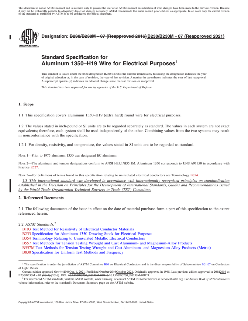
Designation: B230/B230M − 07 (Reapproved 2016) B230/B230M − 07 (Reapproved 2021)
Standard Specification for
Aluminum 1350–H19 Wire for Electrical Purposes
This standard is issued under the fixed designation B230/B230M; the number immediately following the designation indicates the year
of original adoption or, in the case of revision, the year of last revision. A number in parentheses indicates the year of last reapproval.
A superscript epsilon (´) indicates an editorial change since the last revision or reapproval.
This standard has been approved for use by agencies of the U.S. Department of Defense.
1. Scope
1.1 This specification covers aluminum 1350–H19 (extra hard) round wire for electrical purposes.
1.2 The values stated in inch-pound or SI units are to be regarded separately as standard. The values in each system are not exact
equivalents; therefore, each system shall be used independently of the other. Combining values from the two systems may result
in nonconformance with the specification.
1.2.1 For density, resistivity, and temperature, the values stated in SI units are to be regarded as standard.
NOTE 1—Prior to 1975 aluminum 1350 was designated EC aluminum.
NOTE 2—The aluminum and temper designations conform to ANSI H35.1/H35.1M. Aluminum 1350 corresponds to UNS A91350 in accordance with
Practice E527.
NOTE 3—For definitions of terms found in this specification relating to uninsulated electrical conductors see Terminology B354.
1.3 This international standard was developed in accordance with internationally recognized principles on standardization
established in the Decision on Principles for the Development of International Standards, Guides and Recommendations issued
by the World Trade Organization Technical Barriers to Trade (TBT) Committee.
2. Referenced Documents
2.1 The following documents of the issue in effect on the date of material purchase form a part of this specification to the extent
referenced herein.
2.2 ASTM Standards:
B193 Test Method for Resistivity of Electrical Conductor Materials
B233 Specification for Aluminum 1350 Drawing Stock for Electrical Purposes
B354 Terminology Relating to Uninsulated Metallic Electrical Conductors
B557 Test Methods for Tension Testing Wrought and Cast Aluminum- and Magnesium-Alloy Products
B557M Test Methods for Tension Testing Wrought and Cast Aluminum- and Magnesium-Alloy Products (Metric)
B830 Specification for Uniform Test Methods and Frequency
This specification is under the jurisdiction of ASTM Committee B01 on Electrical Conductors and is the direct responsibility of Subcommittee B01.07 on Conductors
of Light Metals.
Current edition approved Oct. 1, 2016Oct. 1, 2021. Published October 2016October 2021. Originally approved in 1948. Last previous edition approved in 20122016 as
B230/B230M – 07 (2012).(2016). DOI: 10.1520/B0230_B0230M-07R16.10.1520/B0230_B0230M-07R21.
For referenced ASTM standards, visit the ASTM website, www.astm.org, or contact ASTM Customer Service at service@astm.org. For Annual Book of ASTM Standards
volume information, refer to the standard’s Document Summary page on the ASTM website.
Copyright © ASTM International, 100 Barr Harbor Drive, PO Box C700, West Conshohocken, PA 19428-2959. United States
B230/B230M − 07 (2021)
E527 Practice for Numbering Metals and Alloys in the Unified Numbering System (UNS)
2.3 ANSI Standard:
ANSI H35.1 American National Standard for Alloy and Temper Designations Systems for Aluminum
ANSI H35.1M American National Standard for Alloy and Temper Systems for Aluminum [Metric]
2.4 NIST Document:
NBS Handbook 100 Copper Wire Tables
3. Terminology
3.1 Definitions of Terms Specific to This Standard:
3.1.1 lot—a group of production units, up to 30 000 lb [15 000 kg] of mass, of one type and size of wire, which was produced
during the same time period, under similar production conditions, and is presented for acceptance at the same time (Explanatory
Note 1 and Note 2).
3.1.2 production unit—a coil, reel, spool, or other package of wire that represents a single usable length.
3.1.3 sample—the production unit or units from which a test specimen or specimens has been removed, and which is considered
to have properties representative of the lot.
3.1.4 specimen—a length of wire removed for test purposes.
4. Ordering Information
4.1 Orders for material under this specification shall include the following information:
4.1.1 Quantity of each size,
4.1.2 Wire size (see 11.1 and Table 1 or Table 2),
4.1.3 Special tension test, if required (see 7.2 and 7.3),
4.1.4 Frequency of bending test (see 8.1 and 14.5),
4.1.5 Special jointing procedures, if permitted (see 12.2),
TABLE 1 Tensile Strength and Elongation Requirements
Elongation in 10 in., min
Tensile Strength, min ksi
(%)
Diameter, in.
Average for Individual Average for Individual
A
a Lot Tests a Lot Tests
0.0105 to 0.0500 25.0 23.0 . . . . . .
0.0501 to 0.0600 29.0 27.0 1.4 1.2
0.0601 to 0.0700 28.5 27.0 1.5 1.3
0.0701 to 0.0800 28.0 26.5 1.6 1.4
0.0801 to 0.0900 27.5 26.0 1.6 1.5
0.0901 to 0.1000 27.0 25.5 1.6 1.5
0.1001 to 0.1100 26.0 24.5 1.6 1.5
0.1101 to 0.1200 25.5 24.0 1.7 1.6
0.1201 to 0.1400 25.0 23.5 1.8 1.7
0.1401 to 0.1500 24.5 23.5 1.9 1.8
0.1501 to 0.1800 24.0 23.0 2.0 1.9
0.1801 to 0.2100 24.0 23.0 2.1 2.0
0.2101 to 0.2600 23.5 22.5 2.3 2.2
A
For wire diameters within 0.0501 to 0.2600 in., the minimum average tensile
strength for a lot may be estimated from the following logarithmic equation for
process control purposes to meet the requirements of this specification: Tensile
strength, ksi = 17.40 – 3.84 × ln (diameter of wire, in.). Requirements stated in the
table are to be used for all other purposes.
Available from American National Standards Institute (ANSI), 25 W. 43rd St., 4th Floor, New York, NY 10036, http://www.ansi.org.
Available from National Institute of Standards and Technology (NIST), 100 Bureau Dr., Stop 1070, Gaithersburg, MD 20899-1070, http://www.nist.gov.
B230/B230M − 07 (2021)
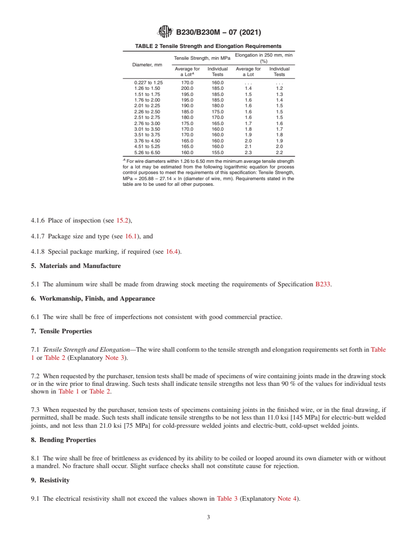
TABLE 2 Tensile Strength and Elongation Requirements
Elongation in 250 mm, min
Tensile Strength, min MPa
(%)
Diameter, mm
Average for Individual Average for Individual
A
a Lot Tests a Lot Tests
0.227 to 1.25 170.0 160.0 . . . . . .
1.26 to 1.50 200.0 185.0 1.4 1.2
1.51 to 1.75 195.0 185.0 1.5 1.3
1.76 to 2.00 195.0 185.0 1.6 1.4
2.01 to 2.25 190.0 180.0 1.6 1.5
2.26 to 2.50 185.0 175.0 1.6 1.5
2.51 to 2.75 180.0 170.0 1.6 1.5
2.76 to 3.00 175.0 165.0 1.7 1.6
3.01 to 3.50 170.0 160.0 1.8 1.7
3.51 to 3.75 170.0 160.0 1.9 1.8
3.76 to 4.50 165.0 160.0 2.0 1.9
4.51 to 5.25 165.0 160.0 2.1 2.0
5.26 to 6.50 160.0 155.0 2.3 2.2
A
For wire diameters within 1.26 to 6.50 mm the minimum average tensile strength
for a lot may be estimated from the following logarithmic equation for process
control purposes to meet the requirements of this specification: Tensile Strength,
MPa = 205.88 – 27.14 × ln (diameter of wire, mm). Requirements stated in the
table are to be used for all other purposes.
4.1.6 Place of inspection (see 15.2),
4.1.7 Package size and type (see 16.1), and
4.1.8 Special package marking, if required (see 16.4).
5. Materials and Manufacture
5.1 The aluminum wire shall be made from drawing stock meeting the requirements of Specification B233.
6. Workmanship, Finish, and Appearance
6.1 The wire shall be free of imperfections not consistent with good commercial practice.
7. Tensile Properties
7.1 Tensile Strength and Elongation—The wire shall conform to the tensile strength and elongation requirements set forth in Table
1 or Table 2 (Explanatory Note 3).
7.2 When requested by the purchaser, tension tests shall be made of specimens of wire containing joints made in the drawing stock
or in the wire prior to final drawing. Such tests shall indicate tensile strengths not less than 90 % of the values for individual tests
shown in Table 1 or Table 2.
7.3 When requested by the purchaser, tension tests of specimens containing joints in the finished wire, or in the final drawing, if
permitted, shall be made. Such tests shall indicate tensile strengths to be not less than 11.0 ksi [145 MPa] for electric-butt welded
joints, and not less than 21.0 ksi [75 MPa] for cold-pressure welded joints and electric-butt, cold-upset welded joints.
8. Bending Properties
8.1 The wire shall be free of brittleness as evidenced by its ability to be coiled or looped around its own diameter with or without
a mandrel. No fracture shall occur. Slight surface checks shall not constitute cause for rejection.
9. Resistivity
9.1 The electrical resistivity shall not exceed the values shown in Table 3 (Explanatory Note 4).
B230/B230M − 07 (2021)
A
TABLE 3 Electrical Resistivity Requirements at 20°C (68°F)20 °C [68 °F] and Equivalent Copper Resistivity
NOTE 1—The values in boldface are standard; other values are for information only.
Volume
Electrical Resistivity
Conductivity
Volume Mass
%IACS
2 2 2
Ω·mm /m μΩin. μΩ·cm Ω·cmil/ft Ω·lb/mile ·g/m
Average for lot 61.2 0.028172 1.1091 2.8172 16.946 434.81 0.076149
Individual tests 61.0 0.028265 1.1128 2.8265 17.002 436.23 0.076399
Copper equivalent 100.0 0.017241 0.67879 1.7241 10.371 875.20 0.15328
A 2
The equivalent resistivity values for 100 % IACS conductivity were each computed from the fundamental IEC value ( ⁄58 Ω·mm /m) using conversion factors each accurate
to at least seven significant figures. Corresponding values for aluminum conductivities were derived from these by multiplying by the reciprocal of the conductivity ratios
and, where applicable, also by the density ratios, both accurate to at least seven significant figures.
10. Density
10.1 For the purpose of calculating linear density, cross section, and so forth, the density of aluminum 1350 shall be taken as 2705
3 3
kg/m [0.0975 lb/in. ] at 20°C [68°F].20 °C [68 °F].
11. Diameter
11.1 The diameter of the wire shall be specified in inches to the nearest 0.0001 in. or the diameter of the wire shall be specified
in millimetres to the nearest 0.001 mm for wires less than 1.000 mm in diameter, and to the nearest 0.01 mm for wires 1.00 mm
in diameter and larger. The actual wire diameter shall not vary from the specified diameter by more than the values shown in Table
4.
12. Joints
12.1 No joints shall be made in the finished wire except as provided in 12.2. Joints may be made in the drawing stock and in the
wire prior to final drawing and shall be in accordance with good commercial practice.
12.2 If agreed upon between the manufacturer and the purchaser, joints may be made during the final drawing or in the finished
wire by electric-butt welding, cold-pressure welding, or electric-butt, cold-upset welding, subject to the following limitations.
12.2.1 For wire sizes from 0.0100 to 0.0555 in. [0.225 to 1.25 mm] in diameter not more than three such joints shall be present
in any coil, reel, or spool of the specified nominal mass.
12.2.2 For wire sizes greater than 0.0500 in. [1.25 mm] diameter, not more than 10 % of the coils, reels, or spools shall contain
such joints, and no such joint shall be closer than 50 ft [15 m] to another joint or to either end of the wire. Not more than two
such joints shall be present in any coil, reel or spool of the specified nominal mass.
13. Sampling
13.1 Sampling—Four test specimens shall be obtained, one from each of four production units (Explanatory Note 1) or in
accordance with the statistical sampling methods as prescribed by Specification B830.
14. Test Methods
14.1 Diameter—Measure the diameter of each specimen with a micrometer caliper graduated in 0.0001-in. increments or measure
the diameter of each specimen with a micrometer caliper graduated in minimum 0.005 mm increments for wires less than 1.00 mm
in diameter, or minimum 0.01-mm increments for wires 1.00 mm in diameter and larger. Take two measurements at one point, with
the second measurement across the cross-sectional diameter 90° rotated from the first measurement. Average the two measurements
TABLE 4 Diameter Tolerances
Permissible Variations of the Mean
Specified Diameter
Diameter from the Specified Diameter,
in. mm
Plus and Minus
0.0105 to 0.0359 up to 0.999 0.0005 in. 0.010 mm
0.0360 to 0.0999 1.00 to 2.99 0.0010 in. 0.030 mm
0.1000 to 0.2600 3.00 and over 1.0 % 1.0 %
B230/B230M − 07 (2021)
to obtain the specimen diameter. Should the measured diameter of any specimen vary from the specified diameter by an amount
greater than the tolerance permitted by Table 4, the lot shall be considered to not meet diameter requirements.
14.2 Finish—Make a visual surface finish inspection with the unaided eye (corrective lenses excepted). The surface finish shall
meet the requirements of 6.1. Should any specimen be found unacceptable, the lot shall be considered to not meet surface finish
requirements.
14.3 Tensile strength and elongation may be determined simultaneously. Obtain the tensile strength, in accordance with Test
Methods B557 or B557M, by dividing the maximum load resisted by the tensile specimen by the original cross-sectional area of
the specimen, with the tensile stress to be expressed in ksi [MPa]. Elongation is the percent increase in length of the tensile test
specimen as measured between gage marks originally spaced 10 in. [250 mm] apart on the specimen. Elongation measurements
are not required for wires <0.0500 in. [<1.25 mm] in diameter. Should any part of the fracture take place outside the elongation
gage lines, or if examination of the tensile specimen indicates a flaw, the values obtained may not be representative and a test on
another section of the specimen may be run (Explanatory Note 6).
14.4 Determine the electrical resistivity in accordance with Test Method B193.
14.5 Test Results—A numerical average for the tensile strength, elongation, and resistivity of the four specimens shall be
calculated and shall be considered the lot average.
14.6 Conformance Criteria—To be considered in conformance, the lot average test results shall meet the average for a lot
requirements of Table 1 or Table 2 and Table 3, and the test results of each specimen shall meet the individual tests requirements
of Table 1 or Table 2 and Table 3 unless otherwise specified.
14.6.1 If the lot average results are in conformance, and all of the individual specimen results are in conformance, the lot shall
be considered in conformance.
14.6.2 If the lot average resul
...
Questions, Comments and Discussion
Ask us and Technical Secretary will try to provide an answer. You can facilitate discussion about the standard in here.