


ASTM F303-08(2016)
(Practice)Standard Practices for Sampling for Particles in Aerospace Fluids and Components
Standard Practices for Sampling for Particles in Aerospace Fluids and Components
SIGNIFICANCE AND USE
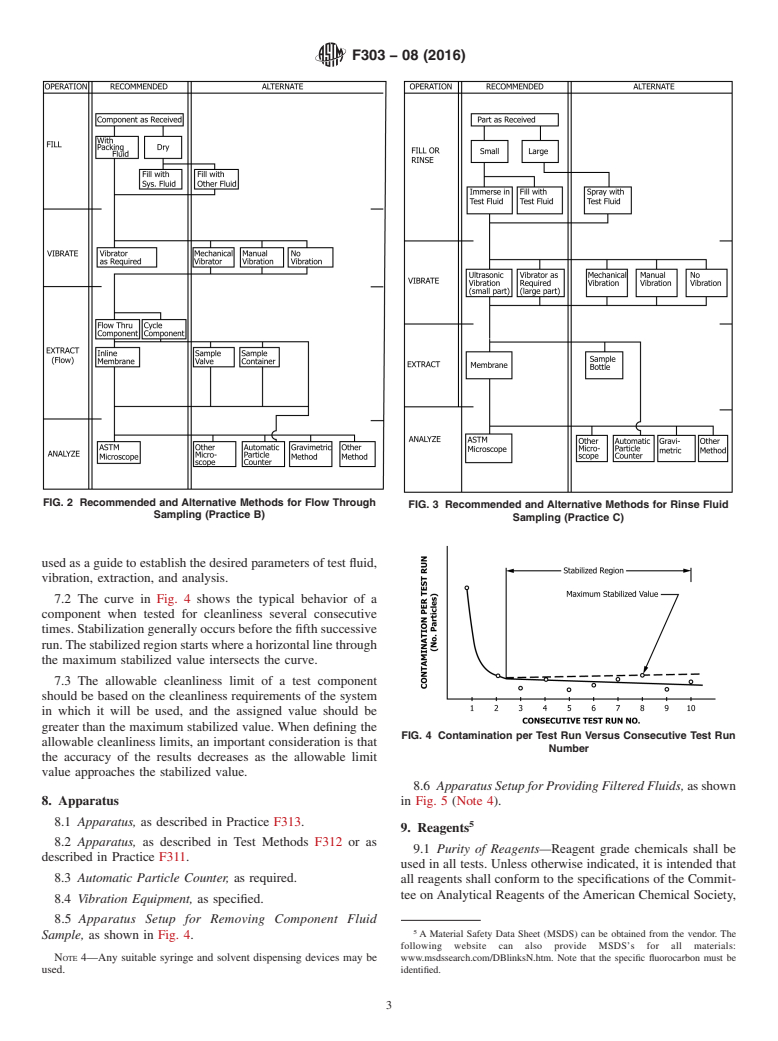
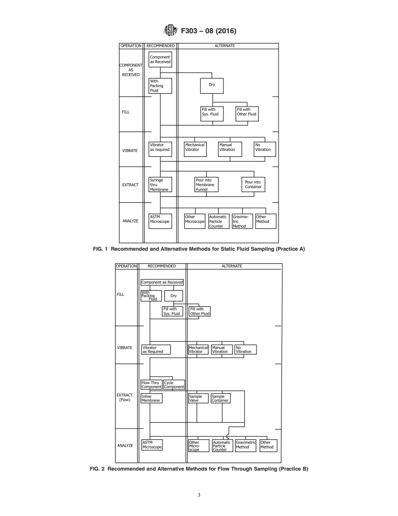
7.1 Although a cleaning action is imparted to the test component, it is not the intent of this practice to serve as a cleaning procedure. Components are normally cleaner after each consecutive test; thus repeated tests may be used to establish process limits for a given component (Fig. 4). A specific set of test parameters must be supplied by the agency specifying cleanliness limits. Fig. 1, Fig. 2, and Fig. 3 may be used as a guide to establish the desired parameters of test fluid, vibration, extraction, and analysis.
7.2 The curve in Fig. 4 shows the typical behavior of a component when tested for cleanliness several consecutive times. Stabilization generally occurs before the fifth successive run. The stabilized region starts where a horizontal line through the maximum stabilized value intersects the curve.
7.3 The allowable cleanliness limit of a test component should be based on the cleanliness requirements of the system in which it will be used, and the assigned value should be greater than the maximum stabilized value. When defining the allowable cleanliness limits, an important consideration is that the accuracy of the results decreases as the allowable limit value approaches the stabilized value.
SCOPE
1.1 These practices cover sampling procedures for use in determining the particle cleanliness of liquids and liquid samples from components. Three practices, A, B, and C, have been developed on the basis of component geometry in order to encompass the wide variety of configurations. These practices establish guidelines to be used in preparing detailed procedures for sampling specific components.
Note 1: The term cleanliness used in these practices refers to solid particles in the liquid. It does not generally cover other foreign matter such as gases, liquids, and products of chemical degradation. Cleanliness with respect to particulate contamination does not necessarily give any indication of the other types of contamination.
1.2 All components, regardless of application, may be tested provided (1) the fluid medium selected is completely compatible with the materials, packing and fluid used in the test component, and test apparatus, and (2) the fluid is handled in accordance with the manufacturer's recommendations and precautions. A liquid shall be used as the test fluid medium. These test fluids may be flushing, rinsing, packing, end use operating, or suitable substitutes for end use operating fluids. (Warning—Practices for sampling surface cleanliness by the vacuum cleaner technique (used on clean room garments and large storage tanks) sampling gaseous fluids and handling hazardous fluids such as oxidizers, acids, propellants, and so forth, are not within the scope of the practices presented; however, they may be included in addendums or separate practices at a later date.
Substitute fluids are recommended in place of end item fluids for preassembly cleanliness determinations on components using hazardous end item fluids. After obtaining the sample, the substitute fluid must be totally removed from the test part with particular caution given to the possibility of trapped fluid. It is hazardous to use a substitute fluid for testing assembled parts where the fluid can be trapped in dead ends, behind seals, and so forth.)
Note 2: The word fluid used in these practices shall be assumed to be a liquid, unless otherwise stated.
1.3 The cleanliness of assemblies with or without moving parts may be determined at the time of test; however, movement of internal component parts during the test will create unknown quantities of contamination from wear. Practice B covers configurations requiring dynamic actuation to achieve a sample. The practice does not differentiate between built-in particles and wear particles.
Note 3: Defining allowable cleanliness limits is not within the scope of these practices.
1.4 The three practices included are as follows:
Sectio...
General Information
Buy Standard
Standards Content (Sample)
NOTICE: This standard has either been superseded and replaced by a new version or withdrawn.
Contact ASTM International (www.astm.org) for the latest information
Designation: F303 − 08 (Reapproved 2016)
Standard Practices for
Sampling for Particles in Aerospace Fluids and
Components
This standard is issued under the fixed designation F303; the number immediately following the designation indicates the year of original
adoption or, in the case of revision, the year of last revision. A number in parentheses indicates the year of last reapproval. A superscript
epsilon (´) indicates an editorial change since the last revision or reapproval.
NOTE 2—The word fluid used in these practices shall be assumed to be
1. Scope
a liquid, unless otherwise stated.
1.1 These practices cover sampling procedures for use in
1.3 The cleanliness of assemblies with or without moving
determining the particle cleanliness of liquids and liquid
parts may be determined at the time of test; however, move-
samples from components. Three practices, A, B, and C, have
ment of internal component parts during the test will create
been developed on the basis of component geometry in order to
unknown quantities of contamination from wear. Practice B
encompass the wide variety of configurations. These practices
covers configurations requiring dynamic actuation to achieve a
establish guidelines to be used in preparing detailed procedures
sample. The practice does not differentiate between built-in
for sampling specific components.
particles and wear particles.
NOTE 1—The term cleanliness used in these practices refers to solid
NOTE 3—Defining allowable cleanliness limits is not within the scope
particles in the liquid. It does not generally cover other foreign matter such
of these practices.
as gases, liquids, and products of chemical degradation. Cleanliness with
respect to particulate contamination does not necessarily give any indica-
1.4 The three practices included are as follows:
tion of the other types of contamination.
Sections
1.2 All components, regardless of application, may be tested
Practice A—Static Fluid Sampling (Method for 5 – 13
extracting fluid from the test article for analysis.
provided (1) the fluid medium selected is completely compat-
This applies to components that have a cavity from
ible with the materials, packing and fluid used in the test
which fluid may be extracted)
component, and test apparatus, and (2) the fluid is handled in
Practice B—Flowing Fluid Sampling (Method for flush- 14 – 22
ing contaminants from the test article for analysis.
accordance with the manufacturer’s recommendations and
This applies to components which fluid can pass (1)
precautions. A liquid shall be used as the test fluid medium.
directly through, or (2) pass into and out of by cy-
These test fluids may be flushing, rinsing, packing, end use cling)
Practice C—Rinse Fluid Sampling (Method for rinsing 23 – 31
operating, or suitable substitutes for end use operating fluids.
contaminants from the test article’s surfaces. The
(Warning—Practices for sampling surface cleanliness by the
rinse fluid is analyzed for contamination. This ap-
vacuum cleaner technique (used on clean room garments and plies to components that do not have a fluid cavity
or for other reasons are not adaptable to Practices
large storage tanks) sampling gaseous fluids and handling
A and B)
hazardous fluids such as oxidizers, acids, propellants, and so
1.5 This standard does not purport to address all of the
forth, are not within the scope of the practices presented;
safety concerns, if any, associated with its use. It is the
however, they may be included in addendums or separate
responsibility of the user of this standard to establish appro-
practices at a later date.
priate safety and health practices and determine the applica-
Substitute fluids are recommended in place of end item fluids
bility of regulatory limitations prior to use.
for preassembly cleanliness determinations on components
using hazardous end item fluids. After obtaining the sample,
2. Referenced Documents
the substitute fluid must be totally removed from the test part
2.1 ASTM Standards:
with particular caution given to the possibility of trapped fluid.
D1836 Specification for Commercial Hexanes
It is hazardous to use a substitute fluid for testing assembled
F311 Practice for Processing Aerospace Liquid Samples for
parts where the fluid can be trapped in dead ends, behind seals,
Particulate Contamination Analysis Using Membrane Fil-
and so forth.)
ters
These practices are under the jurisdiction of ASTM Committee E21 on Space
Simulation and Applications of Space Technology and are the direct responsibility
of Subcommittee E21.05 on Contamination. For referenced ASTM standards, visit the ASTM website, www.astm.org, or
Current edition approved Oct. 1, 2016. Published October 2016. Originally contact ASTM Customer Service at service@astm.org. For Annual Book of ASTM
approved in 1965 as D2429–65 T. Redesignated F303 in 1970. Last previous edition Standards volume information, refer to the standard’s Document Summary page on
approved in 2008 as F303 – 08. DOI: 10.1520/F0303-08R16. the ASTM website.
Copyright © ASTM International, 100 Barr Harbor Drive, PO Box C700, West Conshohocken, PA 19428-2959. United States
F303 − 08 (2016)
F312 Test Methods for Microscopical Sizing and Counting have been recognized due to the wide variety of components
Particles from Aerospace Fluids on Membrane Filters and different test equipment used by industry. Recommended
F313 Test Method for Insoluble Contamination of Hydraulic and alternative methods are given in Fig. 1, Fig. 2, and Fig. 3.
Fluids by Gravimetric Analysis (Withdrawn 1988)
PRACTICE A—STATIC FLUID SAMPLING
2.2 Military Standards:
MIL-T-27602 Trichlorine Oxygen Propellant Compatibles
5. Scope
MIL-H-6083 Hydraulic Fluid Petroleum Base for Pressure
5.1 This practice covers procedures for determining the
MIL-H-5606 Hydraulic Fluid Petroleum Base for Aircarrier
particulate contamination level of fluids from components that
Missiles and Ordinance
have a cavity from which fluid may be extracted.
3. Terminology
6. Summary of Practice
3.1 Definitions:
6.1 Fluid is extracted from the component and analyzed to
3.1.1 analytical membrane—a membrane filter used to col-
determine the particulate contamination level. Recommended
lect the contaminant particles for analysis.
and alternative methods are given in Fig. 1.
3.1.2 azeotropic mixture—a solution of two or more liquids,
6.2 It is recommended that all operations of this practice be
the composition of which does not change upon distillation.
conducted in a dust controlled area. Cleanliness level of the
Also known as azeotrope.
dust controlled area shall be consistent with the component
3.1.3 blank analysis—sometimes referred to as “fluid tare,”
contamination limits.
“control level,” “reference contamination level,” or “back-
ground level.” The blank analysis is the particulate contami-
7. Significance and Use
nation level of the test fluid when the test part is omitted.
7.1 Although a cleaning action is imparted to the test
3.1.4 cleanup membrane—a membrane used to filter the
component, it is not the intent of this practice to serve as a
contaminant particles from the fluid medium.
cleaning procedure. Components are normally cleaner after
3.1.5 component—an individual piece or a complete assem-
each consecutive test; thus repeated tests may be used to
bly of individual pieces.
establish process limits for a given component (Fig. 4). A
specific set of test parameters must be supplied by the agency
3.1.6 field filter holder—a throw-away or reusable cartridge
specifying cleanliness limits. Fig. 1, Fig. 2, and Fig. 3 may be
containing an analytical membrane filter.
3.1.7 initial cleanliness—the measure of contamination re-
moved from the test component at the time of test, excluding
that defined by operating cleanliness.
3.1.8 membrane tare—sometimes referred to as “blank
count” or “control filter.” When applied to microscope
methods, the membrane tare is the quantity of particles
determined to be on the filter before the test fluid is filtered.
When applied to gravimetric methods, the membrane tare is an
amount of weight increase imparted to the control filter when
uncontaminated test fluid is passed through.
3.1.9 operating cleanliness—the measure of contaminants
generated by moving parts in the component during a specified
period of dynamic operation.
3.1.10 solvent filtering dispenser—an apparatus to dispense
a stream of 2.0 µm or finer membrane filtered fluid.
3.1.11 system tare—The measure of contamination deter-
mined by replacing the test component with a connecting
fitting and following the cleanliness test procedure as if
checking the test component.
4. Summary of Practices
4.1 Cleanliness is determined by sampling and analyzing
fluid that has been in contact with the surface being analyzed.
Specific methods are recommended; however, other methods
The last approved version of this historical standard is referenced on
www.astm.org.
FIG. 1 Recommended and Alternative Methods for Static Fluid
Available from Standardization Documents Order Desk, Bldg. 4 Section D, 700
Robbins Ave., Philadelphia, PA 19111-5098, Attn: NPODS. Sampling (Practice A)
F303 − 08 (2016)
FIG. 2 Recommended and Alternative Methods for Flow Through
FIG. 3 Recommended and Alternative Methods for Rinse Fluid
Sampling (Practice B)
Sampling (Practice C)
used as a guide to establish the desired parameters of test fluid,
vibration, extraction, and analysis.
7.2 The curve in Fig. 4 shows the typical behavior of a
component when tested for cleanliness several consecutive
times. Stabilization generally occurs before the fifth successive
run. The stabilized region starts where a horizontal line through
the maximum stabilized value intersects the curve.
7.3 The allowable cleanliness limit of a test component
should be based on the cleanliness requirements of the system
in which it will be used, and the assigned value should be
greater than the maximum stabilized value. When defining the
FIG. 4 Contamination per Test Run Versus Consecutive Test Run
allowable cleanliness limits, an important consideration is that
Number
the accuracy of the results decreases as the allowable limit
value approaches the stabilized value.
8.6 Apparatus Setup for Providing Filtered Fluids, as shown
8. Apparatus
in Fig. 5 (Note 4).
8.1 Apparatus, as described in Practice F313.
9. Reagents
8.2 Apparatus, as described in Test Methods F312 or as
9.1 Purity of Reagents—Reagent grade chemicals shall be
described in Practice F311.
used in all tests. Unless otherwise indicated, it is intended that
8.3 Automatic Particle Counter, as required.
all reagents shall conform to the specifications of the Commit-
tee on Analytical Reagents of the American Chemical Society,
8.4 Vibration Equipment, as specified.
8.5 Apparatus Setup for Removing Component Fluid
A Material Safety Data Sheet (MSDS) can be obtained from the vendor. The
Sample, as shown in Fig. 4.
following website can also provide MSDS’s for all materials:
NOTE 4—Any suitable syringe and solvent dispensing devices may be
www.msdssearch.com/DBlinksN.htm. Note that the specific fluorocarbon must be
used. identified.
F303 − 08 (2016)
FIG. 5 Apparatus Setup for Providing Filtered Fluids
FIG. 6 Apparatus Setup for Removing Component Fluid Sample
where such specifications are available. Other grades may be
used, provided it is first ascertained that the reagent is of
sufficiently high purity to permit its use without lessening the
bly of the apparatus shown in Fig. 6. (Warning—All connec-
accuracy of the determination.
tions must be finger tight only.)
9.2 Reagents must be compatible with the materials, fluid, 10.1.1 Install the double valve and fluid outlet plastic tube.
10.1.2 Remove caps or plugs, or both, from the field filter
and seals used in the component and apparatus.
holder and place them in a covered, precleaned, petri dish.
9.3 All reagents shall be prefiltered through a 2-µm or finer
10.1.3 Install the field filter holder onto the double valve,
absolute membrane filter prior to use unless this requirement is
taking care to place the inlet side of the field filter holder
impractical due to the fluid used or sizes monitored in which
towards the fluid being withdrawn.
case the user must filter as necessary.
10.1.4 Install fluid inlet needle onto the monitor.
9.4 Low surface tension reagents commonly used are as
(Warning—The fluid inlet needle must be precleaned prior to
follows:
each usage.)
9.4.1 Petroleum Ether,
10.2 General Requirements for Fig. 6:
9.4.2 Hexane, in accordance with Specification D1836.
10.2.1 A control blank must be accomplished on the appa-
9.4.3 Isopropyl Alcohol,
ratus setup before fluid is withdrawn for component fluid
9.4.4 Fluorocarbons,
sampling.
9.4.5 Mineral Spirits,
10.2.2 It is recommended that the field filter holders be used
9.4.6 Trichloroethylene, in accordance with MIL-T-27602,
one time only for component fluid sampling. However, clean-
and
ing in sufficient numbers might warrant their reuse, provided it
9.4.7 Azeotropic mixture of ethyl acetate (47 % vol) and
is first determined that the monitors are sufficiently cleaned to
cyclohexane (53 % vol).
permit their reuse without lessening the accuracy of the
9.4.8 Deionized water.
determination.
10.2.3 Always actuate the syringe plunger slowly when
NOTE 5—Methyl-chloroform, used in these practices, is toxic, and is
filling or ejecting fluid.
being phased out for many applications. Methyl-chloroform has been
10.2.4 For ease of actuation, the syringe plunger must be
replaced in this edition of these practices. The replacement solvents were
lubricated. If the plunger is extremely hard to actuate, check
selected based on tests and analyses performed by The Aerospace
the plunger seal for swelling which would indicate noncom-
Corporation and described in SMC-TR-95–28.
NOTE 6—Trichloroethylene has been labeled a potential human carcino- patibility with the fluids utilized.
gen by the Environmental Protection Agency. Use should be restricted to
10.2.5 In order to minimize seal swell, it is desirable to
limit human exposure.
remove the syringe plunger when not in use. Lubricate prior to
each reassembly.
10. Preparation of Apparatus
10.3 Installation Requirements for Fig. 7—The following
10.1 Installation Requirements for Fig. 6—The following
requirements must be accomplished prior to and during assem-
requirements must be accomplished prior to and during assem-
bly on the apparatus shown in Fig. 7. (Warning—See 10.1.)
10.3.1 Eject all fluid from the syringe.
Reagent Chemicals, American Chemical Society Specifications, American
10.3.2 Install the hypodermic adapter a
...
This document is not an ASTM standard and is intended only to provide the user of an ASTM standard an indication of what changes have been made to the previous version. Because
it may not be technically possible to adequately depict all changes accurately, ASTM recommends that users consult prior editions as appropriate. In all cases only the current version
of the standard as published by ASTM is to be considered the official document.
Designation: F303 − 08 F303 − 08 (Reapproved 2016)
Standard Practices for
Sampling for Particles in Aerospace Fluids and
Components
This standard is issued under the fixed designation F303; the number immediately following the designation indicates the year of original
adoption or, in the case of revision, the year of last revision. A number in parentheses indicates the year of last reapproval. A superscript
epsilon (´) indicates an editorial change since the last revision or reapproval.
1. Scope
1.1 These practices cover sampling procedures for use in determining the particle cleanliness of liquids and liquid samples from
components. Three practices, A, B, and C, have been developed on the basis of component geometry in order to encompass the
wide variety of configurations. These practices establish guidelines to be used in preparing detailed procedures for sampling
specific components.
NOTE 1—The term cleanliness used in these practices refers to solid particles in the liquid. It does not generally cover other foreign matter such as
gases, liquids, and products of chemical degradation. Cleanliness with respect to particulate contamination does not necessarily give any indication of
the other types of contamination.
1.2 All components, regardless of application, may be tested provided (1) the fluid medium selected is completely compatible
with the materials, packing and fluid used in the test component, and test apparatus, and (2) the fluid is handled in accordance with
the manufacturer’s recommendations and precautions. A liquid shall be used as the test fluid medium. These test fluids may be
flushing, rinsing, packing, end use operating, or suitable substitutes for end use operating fluids. (Warning—Practices for sampling
surface cleanliness by the vacuum cleaner technique (used on clean room garments and large storage tanks) sampling gaseous
fluids and handling hazardous fluids such as oxidizers, acids, propellants, and so forth, are not within the scope of the practices
presented; however, they may be included in addendums or separate practices at a later date.
Substitute fluids are recommended in place of end item fluids for preassembly cleanliness determinations on components using
hazardous end item fluids. After obtaining the sample, the substitute fluid must be totally removed from the test part with particular
caution given to the possibility of trapped fluid. It is hazardous to use a substitute fluid for testing assembled parts where the fluid
can be trapped in dead ends, behind seals, and so forth.)
NOTE 2—The word fluid used in these practices shall be assumed to be a liquid, unless otherwise stated.
1.3 The cleanliness of assemblies with or without moving parts may be determined at the time of test; however, movement of
internal component parts during the test will create unknown quantities of contamination from wear. Practice B covers
configurations requiring dynamic actuation to achieve a sample. The practice does not differentiate between built-in particles and
wear particles.
NOTE 3—Defining allowable cleanliness limits is not within the scope of these practices.
1.4 The three practices included are as follows:
Sections
Practice A—Static Fluid Sampling (Method for 5 – 13
extracting fluid from the test article for analysis.
This applies to components that have a cavity from
which fluid may be extracted)
Practice B—Flowing Fluid Sampling (Method for flush- 14 – 22
ing contaminants from the test article for analysis.
This applies to components which fluid can pass (1)
directly through, or (2) pass into and out of by cy-
cling)
Practice C—Rinse Fluid Sampling (Method for rinsing 23 – 31
contaminants from the test article’s surfaces. The
rinse fluid is analyzed for contamination. This ap-
plies to components that do not have a fluid cavity
or for other reasons are not adaptable to Practices
A and B)
These practices are under the jurisdiction of ASTM Committee E21 on Space Simulation and Applications of Space Technology and are the direct responsibility of
Subcommittee E21.05 on Contamination.
Current edition approved Nov. 1, 2008Oct. 1, 2016. Published December 2008October 2016. Originally approved in 1965 as D2429–65 T. Redesignated F303 in 1970.
Last previous edition approved in 20022008 as F303 – 02.F303 – 08. DOI: 10.1520/F0303-08.10.1520/F0303-08R16.
Copyright © ASTM International, 100 Barr Harbor Drive, PO Box C700, West Conshohocken, PA 19428-2959. United States
F303 − 08 (2016)
1.5 This standard does not purport to address all of the safety concerns, if any, associated with its use. It is the responsibility
of the user of this standard to establish appropriate safety and health practices and determine the applicability of regulatory
limitations prior to use.
2. Referenced Documents
2.1 ASTM Standards:
D1836 Specification for Commercial Hexanes
F311 Practice for Processing Aerospace Liquid Samples for Particulate Contamination Analysis Using Membrane Filters
F312 Test Methods for Microscopical Sizing and Counting Particles from Aerospace Fluids on Membrane Filters
F313 Test Method for Insoluble Contamination of Hydraulic Fluids by Gravimetric Analysis (Withdrawn 1988)
2.2 Military Standards:
MIL-T-27602 Trichlorine Oxygen Propellant Compatibles
MIL-H-6083 Hydraulic Fluid Petroleum Base for Pressure
MIL-H-5606 Hydraulic Fluid Petroleum Base for Aircarrier Missiles and Ordinance
3. Terminology
3.1 Definitions:
3.1.1 analytical membrane—a membrane filter used to collect the contaminant particles for analysis.
3.1.2 azeotropic mixture—a solution of two or more liquids, the composition of which does not change upon distillation. Also
known as azeotrope.
3.1.3 blank analysis—sometimes referred to as “fluid tare,” “control level,” “reference contamination level,” or “background
level.” The blank analysis is the particulate contamination level of the test fluid when the test part is omitted.
3.1.4 cleanup membrane—a membrane used to filter the contaminant particles from the fluid medium.
3.1.5 component—an individual piece or a complete assembly of individual pieces.
3.1.6 field filter holder—a throw-away or reusable cartridge containing an analytical membrane filter.
3.1.7 initial cleanliness—the measure of contamination removed from the test component at the time of test, excluding that
defined by operating cleanliness.
3.1.8 membrane tare—sometimes referred to as “blank count” or “control filter.” When applied to microscope methods, the
membrane tare is the quantity of particles determined to be on the filter before the test fluid is filtered. When applied to gravimetric
methods, the membrane tare is an amount of weight increase imparted to the control filter when uncontaminated test fluid is passed
through.
3.1.9 operating cleanliness—the measure of contaminants generated by moving parts in the component during a specified period
of dynamic operation.
3.1.10 solvent filtering dispenser—an apparatus to dispense a stream of 2.0 μm or finer membrane filtered fluid.
3.1.11 system tare—The measure of contamination determined by replacing the test component with a connecting fitting and
following the cleanliness test procedure as if checking the test component.
4. Summary of Practices
4.1 Cleanliness is determined by sampling and analyzing fluid that has been in contact with the surface being analyzed. Specific
methods are recommended; however, other methods have been recognized due to the wide variety of components and different test
equipment used by industry. Recommended and alternative methods are given in Fig. 1, Fig. 2, and Fig. 3.
PRACTICE A—STATIC FLUID SAMPLING
5. Scope
5.1 This practice covers procedures for determining the particulate contamination level of fluids from components that have a
cavity from which fluid may be extracted.
6. Summary of Practice
6.1 Fluid is extracted from the component and analyzed to determine the particulate contamination level. Recommended and
alternative methods are given in Fig. 1.
For referenced ASTM standards, visit the ASTM website, www.astm.org, or contact ASTM Customer Service at service@astm.org. For Annual Book of ASTM Standards
volume information, refer to the standard’s Document Summary page on the ASTM website.
The last approved version of this historical standard is referenced on www.astm.org.
Available from Standardization Documents Order Desk, Bldg. 4 Section D, 700 Robbins Ave., Philadelphia, PA 19111-5098, Attn: NPODS.
F303 − 08 (2016)
FIG. 1 Recommended and Alternative Methods for Static Fluid Sampling (Practice A)
FIG. 2 Recommended and Alternative Methods for Flow Through Sampling (Practice B)
F303 − 08 (2016)
FIG. 3 Recommended and Alternative Methods for Rinse Fluid Sampling (Practice C)
6.2 It is recommended that all operations of this practice be conducted in a dust controlled area. Cleanliness level of the dust
controlled area shall be consistent with the component contamination limits.
7. Significance and Use
7.1 Although a cleaning action is imparted to the test component, it is not the intent of this practice to serve as a cleaning
procedure. Components are normally cleaner after each consecutive test; thus repeated tests may be used to establish process limits
for a given component (Fig. 4). A specific set of test parameters must be supplied by the agency specifying cleanliness limits. Fig.
1, Fig. 2, and Fig. 3 may be used as a guide to establish the desired parameters of test fluid, vibration, extraction, and analysis.
7.2 The curve in Fig. 4 shows the typical behavior of a component when tested for cleanliness several consecutive times.
Stabilization generally occurs before the fifth successive run. The stabilized region starts where a horizontal line through the
maximum stabilized value intersects the curve.
FIG. 4 Contamination per Test Run Versus Consecutive Test Run Number
F303 − 08 (2016)
7.3 The allowable cleanliness limit of a test component should be based on the cleanliness requirements of the system in which
it will be used, and the assigned value should be greater than the maximum stabilized value. When defining the allowable
cleanliness limits, an important consideration is that the accuracy of the results decreases as the allowable limit value approaches
the stabilized value.
8. Apparatus
8.1 Apparatus, as described in Practice F313.
8.2 Apparatus, as described in Test Methods F312 or as described in Practice F311.
8.3 Automatic Particle Counter, as required.
8.4 Vibration Equipment, as specified.
8.5 Apparatus Setup for Removing Component Fluid Sample, as shown in Fig. 4.
NOTE 4—Any suitable syringe and solvent dispensing devices may be used.
8.6 Apparatus Setup for Providing Filtered Fluids, as shown in Fig. 5 (Note 4).
9. Reagents
9.1 Purity of Reagents—Reagent grade chemicals shall be used in all tests. Unless otherwise indicated, it is intended that all
reagents shall conform to the specifications of the Committee on Analytical Reagents of the American Chemical Society, where
such specifications are available. Other grades may be used, provided it is first ascertained that the reagent is of sufficiently high
purity to permit its use without lessening the accuracy of the determination.
9.2 Reagents must be compatible with the materials, fluid, and seals used in the component and apparatus.
9.3 All reagents shall be prefiltered through a 2-μm or finer absolute membrane filter prior to use unless this requirement is
impractical due to the fluid used or sizes monitored in which case the user must filter as necessary.
9.4 Low surface tension reagents commonly used are as follows:
9.4.1 Petroleum Ether,
9.4.2 Hexane, in accordance with Specification D1836.
9.4.3 Isopropyl Alcohol,
9.4.4 Fluorocarbons,
9.4.5 Mineral Spirits,
9.4.6 Trichloroethylene, in accordance with MIL-T-27602, and
9.4.7 Azeotropic mixture of ethyl acetate (47 % vol) and cyclohexane (53 % vol).
9.4.8 Deionized water.
NOTE 5—Methyl-chloroform, used in these practices, is toxic, and is being phased out for many applications. Methyl-chloroform has been replaced
A Material Safety Data Sheet (MSDS) can be obtained from the vendor. The following website can also provide MSDS’s for all materials: www.msdssearch.com/
DBlinksN.htm. Note that the specific fluorocarbon must be identified.
Reagent Chemicals, American Chemical Society Specifications, American Chemical Society, Washington, DC. For Suggestions on the testing of reagents not listed by
the American Chemical Society, see Annual Standards for Laboratory Chemicals, BDH Ltd., Poole, Dorset, U.K., and the United States Pharmacopeia and National
Formulary, U.S. Pharmacopeial Convention, Inc. (USPC), Rockville, MD.
FIG. 5 Apparatus Setup for Providing Filtered Fluids
F303 − 08 (2016)
in this edition of these practices. The replacement solvents were selected based on tests and analyses performed by The Aerospace Corporation and
described in SMC-TR-95–28.
NOTE 6—Trichloroethylene has been labeled a potential human carcinogen by the Environmental Protection Agency. Use should be restricted to limit
human exposure.
10. Preparation of Apparatus
10.1 Installation Requirements for Fig. 6—The following requirements must be accomplished prior to and during assembly of
the apparatus shown in Fig. 6. (Warning—All connections must be finger tight only.)
10.1.1 Install the double valve and fluid outlet plastic tube.
10.1.2 Remove caps or plugs, or both, from the field filter holder and place them in a covered, precleaned, petri dish.
10.1.3 Install the field filter holder onto the double valve, taking care to place the inlet side of the field filter holder towards the
fluid being withdrawn.
10.1.4 Install fluid inlet needle onto the monitor. (Warning—The fluid inlet needle must be precleaned prior to each usage.)
10.2 General Requirements for Fig. 6:
10.2.1 A control blank must be accomplished on the apparatus setup before fluid is withdrawn for component fluid sampling.
10.2.2 It is recommended that the field filter holders be used one time only for component fluid sampling. However, cleaning
in sufficient numbers might warrant their reuse, provided it is first determined that the monitors are sufficiently cleaned to permit
their reuse without lessening the accuracy of the determination.
10.2.3 Always actuate the syringe plunger slowly when filling o
...
Questions, Comments and Discussion
Ask us and Technical Secretary will try to provide an answer. You can facilitate discussion about the standard in here.