


ASTM C773-88(2016)
(Test Method)Standard Test Method for Compressive (Crushing) Strength of Fired Whiteware Materials
Standard Test Method for Compressive (Crushing) Strength of Fired Whiteware Materials
SIGNIFICANCE AND USE
3.1 Resistance to compression is the measure of the greatest strength of a ceramic material. Ideally, ceramics should be stressed this way in use. This test is a measure of the potential load-bearing usefulness of a ceramic.
SCOPE
1.1 This test method covers two test procedures (A and B) for the determination of the compressive strength of fired whiteware materials.
1.2 Procedure A is generally applicable to whiteware products of low- to moderately high-strength levels (up to 150 000 psi or 1030 MPa).
1.3 Procedure B is specifically devised for testing of high-strength ceramics (over 100 000 psi or 690 MPa).
1.4 This standard does not purport to address all of the safety concerns, if any, associated with its use. It is the responsibility of the user of this standard to establish appropriate safety and health practices and determine the applicability of regulatory limitations prior to use.
General Information
Buy Standard
Standards Content (Sample)
NOTICE: This standard has either been superseded and replaced by a new version or withdrawn.
Contact ASTM International (www.astm.org) for the latest information
Designation: C773 − 88 (Reapproved 2016)
Standard Test Method for
Compressive (Crushing) Strength of Fired Whiteware
Materials
This standard is issued under the fixed designation C773; the number immediately following the designation indicates the year of
original adoption or, in the case of revision, the year of last revision. A number in parentheses indicates the year of last reapproval. A
superscript epsilon (´) indicates an editorial change since the last revision or reapproval.
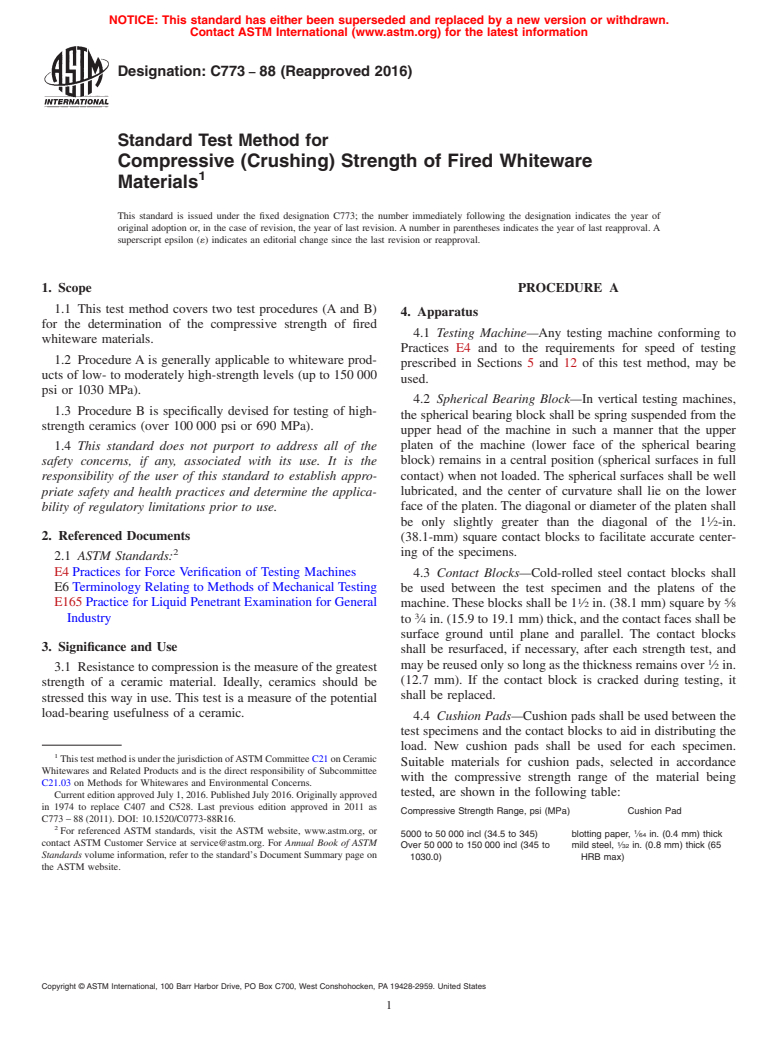
1. Scope PROCEDURE A
1.1 This test method covers two test procedures (A and B)
4. Apparatus
for the determination of the compressive strength of fired
4.1 Testing Machine—Any testing machine conforming to
whiteware materials.
Practices E4 and to the requirements for speed of testing
1.2 Procedure A is generally applicable to whiteware prod-
prescribed in Sections 5 and 12 of this test method, may be
ucts of low- to moderately high-strength levels (up to 150 000
used.
psi or 1030 MPa).
4.2 Spherical Bearing Block—In vertical testing machines,
1.3 Procedure B is specifically devised for testing of high-
the spherical bearing block shall be spring suspended from the
strength ceramics (over 100 000 psi or 690 MPa).
upper head of the machine in such a manner that the upper
1.4 This standard does not purport to address all of the platen of the machine (lower face of the spherical bearing
block) remains in a central position (spherical surfaces in full
safety concerns, if any, associated with its use. It is the
responsibility of the user of this standard to establish appro- contact) when not loaded. The spherical surfaces shall be well
lubricated, and the center of curvature shall lie on the lower
priate safety and health practices and determine the applica-
bility of regulatory limitations prior to use. face of the platen. The diagonal or diameter of the platen shall
be only slightly greater than the diagonal of the 1 ⁄2-in.
2. Referenced Documents
(38.1-mm) square contact blocks to facilitate accurate center-
ing of the specimens.
2.1 ASTM Standards:
E4 Practices for Force Verification of Testing Machines
4.3 Contact Blocks—Cold-rolled steel contact blocks shall
E6 Terminology Relating to Methods of Mechanical Testing
be used between the test specimen and the platens of the
1 5
E165 Practice for Liquid Penetrant Examination for General
machine. These blocks shall be 1 ⁄2 in. (38.1 mm) square by ⁄8
Industry
to ⁄4 in. (15.9 to 19.1 mm) thick, and the contact faces shall be
surface ground until plane and parallel. The contact blocks
3. Significance and Use
shall be resurfaced, if necessary, after each strength test, and
may be reused only so long as the thickness remains over ⁄2 in.
3.1 Resistance to compression is the measure of the greatest
(12.7 mm). If the contact block is cracked during testing, it
strength of a ceramic material. Ideally, ceramics should be
shall be replaced.
stressed this way in use. This test is a measure of the potential
load-bearing usefulness of a ceramic.
4.4 Cushion Pads—Cushion pads shall be used between the
test specimens and the contact blocks to aid in distributing the
load. New cushion pads shall be used for each specimen.
ThistestmethodisunderthejurisdictionofASTMCommitteeC21onCeramic
Suitable materials for cushion pads, selected in accordance
Whitewares and Related Products and is the direct responsibility of Subcommittee
with the compressive strength range of the material being
C21.03 on Methods for Whitewares and Environmental Concerns.
tested, are shown in the following table:
Current edition approved July 1, 2016. Published July 2016. Originally approved
in 1974 to replace C407 and C528. Last previous edition approved in 2011 as
Compressive Strength Range, psi (MPa) Cushion Pad
C773 – 88 (2011). DOI: 10.1520/C0773-88R16.
For referenced ASTM standards, visit the ASTM website, www.astm.org, or 1
5000 to 50 000 incl (34.5 to 345) blotting paper, ⁄64 in. (0.4 mm) thick
contact ASTM Customer Service at service@astm.org. For Annual Book of ASTM 1
Over 50 000 to 150 000 incl (345 to mild steel, ⁄32 in. (0.8 mm) thick (65
Standards volume information, refer to the standard’s Document Summary page on
1030.0) HRB max)
the ASTM website.
Copyright © ASTM International, 100 Barr Harbor Drive, PO Box C700, West Conshohocken, PA 19428-2959. United States
C773 − 88 (2016)
TABLE 1 Typical Loading Rates to Cause Failure in 1 min NOTE 1—It is desirable to include details of the origin of the specimen
and subsequent treatment.
NOTE 1—The loading rate of 16 000 lbf/min (70 kN/min) shall be used
for the first three tests of an unknown material to determine the general
8. Precision and Bias
strength classification group. Some specimens crack before ultimate
8.1 Interlaboratory Test Data—An interlaboratory test was
failure; the load at which the first audible crack occurs shall be noted, but
run in 1979 in which randomly drawn samples of six materials
only the load on the specimen at ultimate failure shall be used for
calculation of compressive strength.
were tested in each of five laboratories. One operator in each
Compressive Strength, psi Specimen Diameter, in. Loading Rate, lbf/min (kN/ laboratory tested ten specimens of each material. The compo-
(MPa) (mm) min)
nents of variance for compressive strength results expressed as
10 000(69) 1.00(25.4) 8000(35)
coefficients of variation were calculated as follows:
50 000(345) 0.64(16.3) 16 000(70)
Single-operator component 1.50 % of the average
150 000(1034) 0.45(11.5) 24 000(105)
Between-laboratory component 8.80 % of the average
8.2 Critical Differences—For the components of variance
reported in 8.1, two averages of observed values should be
5. Procedure
considered significantly different at the 95 % probability level
5.1 Dye-check specimens in accordance with Test Method
if the difference equals or exceeds the following critical
E165 before testing. Discard any pieces exhibiting cracks or
differences listed below:
flaws visible to the unaided eye.
A
Number of Critical Difference, % of Grand Average
5.2 Clean the test specimens with a suitable solvent after
Observations in Each Single-Operator Between-Laboratory
Average Precision Precision
grinding and immerse in an ultrasonic bath filled with hot
detergent solution. Then rinse specimens in hot water, dry at
10 4.16 24.40
110 6 2°C (230 6 4°F) for 2 h and cool to room temperature
A
in a desiccator.
The critical differences were calculated using t = 1.960 which is based on infinite
degrees of freedom.
5.3 Carefully center the specimen in the machine between
8.3 Confidence Limits—For the components of variance
the contact blocks. Place an appropriate guard around the
noted in 8.1, single averages of observed values have the
specimen to contain flying fragments at failure; eye protection
following 95 % confidence limits:
should be used by the operator.
Width of 95 % Confidence Limits, Percent of the
5.4 Apply the load continuously and without impact shock
A
Number of Grand Average
until ultimate failure. The rate of loading to be used shall Observations in Each Single-Operator Between-Laboratory
Average Precision Precis
...
This document is not an ASTM standard and is intended only to provide the user of an ASTM standard an indication of what changes have been made to the previous version. Because
it may not be technically possible to adequately depict all changes accurately, ASTM recommends that users consult prior editions as appropriate. In all cases only the current version
of the standard as published by ASTM is to be considered the official document.
Designation: C773 − 88 (Reapproved 2011) C773 − 88 (Reapproved 2016)
Standard Test Method for
Compressive (Crushing) Strength of Fired Whiteware
Materials
This standard is issued under the fixed designation C773; the number immediately following the designation indicates the year of
original adoption or, in the case of revision, the year of last revision. A number in parentheses indicates the year of last reapproval. A
superscript epsilon (´) indicates an editorial change since the last revision or reapproval.
1. Scope
1.1 This test method covers two test procedures (A and B) for the determination of the compressive strength of fired whiteware
materials.
1.2 Procedure A is generally applicable to whiteware products of low- to moderately high-strength levels (up to 150 000 psi or
1030 MPa).
1.3 Procedure B is specifically devised for testing of high-strength ceramics (over 100 000 psi or 690 MPa).
1.4 This standard does not purport to address all of the safety concerns, if any, associated with its use. It is the responsibility
of the user of this standard to establish appropriate safety and health practices and determine the applicability of regulatory
limitations prior to use.
2. Referenced Documents
2.1 ASTM Standards:
E4 Practices for Force Verification of Testing Machines
E6 Terminology Relating to Methods of Mechanical Testing
E165 Practice for Liquid Penetrant Examination for General Industry
3. Significance and Use
3.1 Resistance to compression is the measure of the greatest strength of a ceramic material. Ideally, ceramics should be stressed
this way in use. This test is a measure of the potential load-bearing usefulness of a ceramic.
PROCEDURE A
4. Apparatus
4.1 Testing Machine—Any testing machine conforming to Practices E4 and to the requirements for speed of testing prescribed
in Sections 5 and 12 of this test method, may be used.
4.2 Spherical Bearing Block—In vertical testing machines, the spherical bearing block shall be spring suspended from the upper
head of the machine in such a manner that the upper platen of the machine (lower face of the spherical bearing block) remains
in a central position (spherical surfaces in full contact) when not loaded. The spherical surfaces shall be well lubricated, and the
center of curvature shall lie on the lower face of the platen. The diagonal or diameter of the platen shall be only slightly greater
than the diagonal of the 1 ⁄2-in. (38.1-mm) square contact blocks to facilitate accurate centering of the specimens.
4.3 Contact Blocks—Cold-rolled steel contact blocks shall be used between the test specimen and the platens of the machine.
1 5 3
These blocks shall be 1 ⁄2 in. (38.1 mm) square by ⁄8 to ⁄4 in. (15.9 to 19.1 mm) thick, and the contact faces shall be surface ground
until plane and parallel. The contact blocks shall be resurfaced, if necessary, after each strength test, and may be reused only so
long as the thickness remains over ⁄2 in. (12.7 mm). If the contact block is cracked during testing, it shall be replaced.
This test method is under the jurisdiction of ASTM Committee C21 on Ceramic Whitewares and Related Products and is the direct responsibility of Subcommittee C21.03
on Methods for Whitewares and Environmental Concerns.
Current edition approved March 1, 2011July 1, 2016. Published March 2011July 2016. Originally approved in 1974 to replace C407 and C528. Last previous edition
approved in 20062011 as C773 – 88 (2011). (2006). DOI: 10.1520/C0773-88R11.10.1520/C0773-88R16.
For referenced ASTM standards, visit the ASTM website, www.astm.org, or contact ASTM Customer Service at service@astm.org. For Annual Book of ASTM Standards
volume information, refer to the standard’s Document Summary page on the ASTM website.
Copyright © ASTM International, 100 Barr Harbor Drive, PO Box C700, West Conshohocken, PA 19428-2959. United States
C773 − 88 (2016)
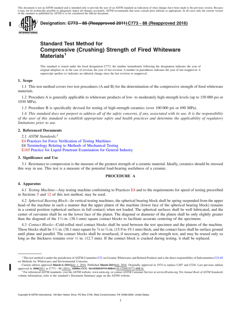
TABLE 1 Typical Loading Rates to Cause Failure in 1 min
NOTE 1—The loading rate of 16 000 lbf/min (70 kN/min) shall be used
for the first three tests of an unknown material to determine the general
strength classification group. Some specimens crack before ultimate
failure; the load at which the first audible crack occurs shall be noted, but
only the load on the specimen at ultimate failure shall be used for
calculation of compressive strength.
Compressive Strength, psi Specimen Diameter, in. Loading Rate, lbf/min (kN/
(MPa) (mm) min)
10 000(69) 1.00(25.4) 8000(35)
50 000(345) 0.64(16.3) 16 000(70)
150 000(1034) 0.45(11.5) 24 000(105)
4.4 Cushion Pads—Cushion pads shall be used between the test specimens and the contact blocks to aid in distributing the load.
New cushion pads shall be used for each specimen. Suitable materials for cushion pads, selected in accordance with the
compressive strength range of the material being tested, are shown in the following table:
Compressive Strength Range, psi (MPa) Cushion Pad
5000 to 50 000 incl (34.5 to 345) blotting paper, ⁄64 in. (0.4 mm) thick
Over 50 000 to 150 000 incl (345 to mild steel, ⁄32 in. (0.8 mm) thick (65
1030.0) HRB max)
5. Procedure
5.1 Dye-check specimens in accordance with Test Method E165 before testing. Discard any pieces exhibiting cracks or flaws
visible to the unaided eye.
5.2 Clean the test specimens with a suitable solvent after grinding and immerse in an ultrasonic bath filled with hot detergent
solution. Then rinse specimens in hot water, dry at 110 6 2°C (230 6 4°F) for 2 h and cool to room temperature in a desiccator.
5.3 Carefully center the specimen in the machine between the contact blocks. Place an appropriate guard around the specimen
to contain flying fragments at failure; eye protection should be used by the operator.
5.4 Apply the load continuously and without impact shock until ultimate failure. The rate of loading to be used shall depend
on the compressive strength of the material being tested, as shown in Table 1.
6. Calculation
6.1 Calculate the compressive strength of each specimen as follows:
C 5 P/A (1)
where:
C = compressive strength of the specimen, psi or MPa;
P = total load on the specimen at failure, lbf or N; and
2 2
A = calculated area of the bearing surface of the specimen, in. or mm .
7. Report
7.1 Report the following information:
7.1.1 The procedure used,
7.1.2 Type of testing machine (hydraulic or screw),
7.1.3 Material and size of contact blocks or of cushioning materials,
7.1.4 Description of material being tested (Note 1),
7.1.5 Rate of loading,
7.1.6 Number of specimens tested,
7.1.7 Dimensions and load at failure of each specimen, and
7.1.8 Compressive strength of each specimen tested, rounded off to the nearest 100 psi (1.0 MPa), together with the average
compressive strength of the sample tested and the standard deviation.
C773 − 88 (2016)
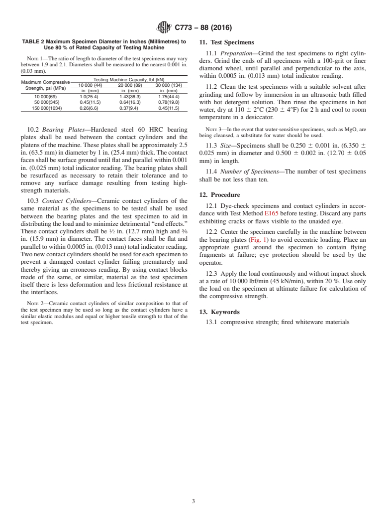
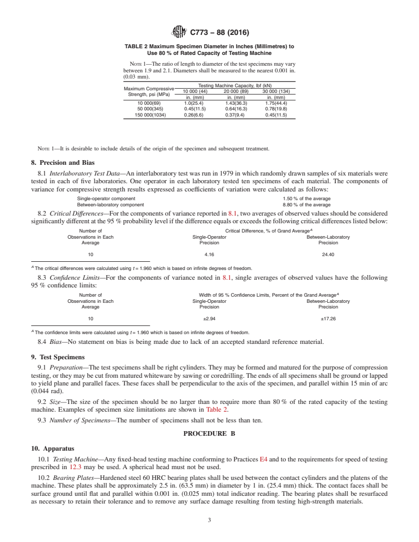
TABLE 2 Maximum Specimen Diameter in Inches (Millimetres) to
Use 80 % of Rated Capacity of Testing Machine
NOTE 1—The ratio of length to diameter of the test specimens may vary
between 1.9 and 2.1. Diameters shall be measured to the nearest 0.001 in.
(0.03 mm).
Testing M
...
Questions, Comments and Discussion
Ask us and Technical Secretary will try to provide an answer. You can facilitate discussion about the standard in here.