

prEN 18380
(Main)Water conditioning equipment inside buildings - Devices using UV LED units - Requirements for performance, safety and testing
- Abstract
This document specifies definitions, principles of construction, requirements and methods for testing the performance of UV devices (240 nm to 290 nm nominal) for potable water installations according to EN 806-2 which are permanently connected to the building’s supply.
Devices described by this document can be installed at the point of entry (POE), within the water distribution system inside the building or at the point of use (POU).
Additionally, the devices described in this document can be used in mobile or temporary potable water installations, where the system is not permanently connected to a water supply.
UV devices in the sense of this document are UV bactericidal treatment devices or UV disinfection devices for one of three specified water qualities, determined by the observed UV transmittance.
Devices can be standalone, integrated into a larger appliance or part of multi-staged treatment process. The document relates solely to the performance of the UV reactor.
- Status
- Not Published
- Publication Date
- 28-Feb-2027
- Technical Committee
- CEN/TC 164 - Water supply
- Drafting Committee
- CEN/TC 164/WG 13 - Water conditioning equipment inside buildings
- Current Stage
- 4020 - Submission to enquiry - Enquiry
- Start Date
- 20-Aug-2026
- Due Date
- 10-Nov-2025
- Completion Date
- 20-Aug-2026
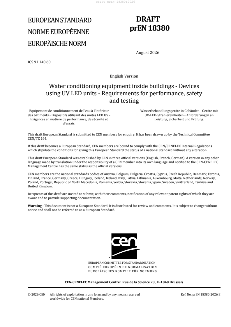

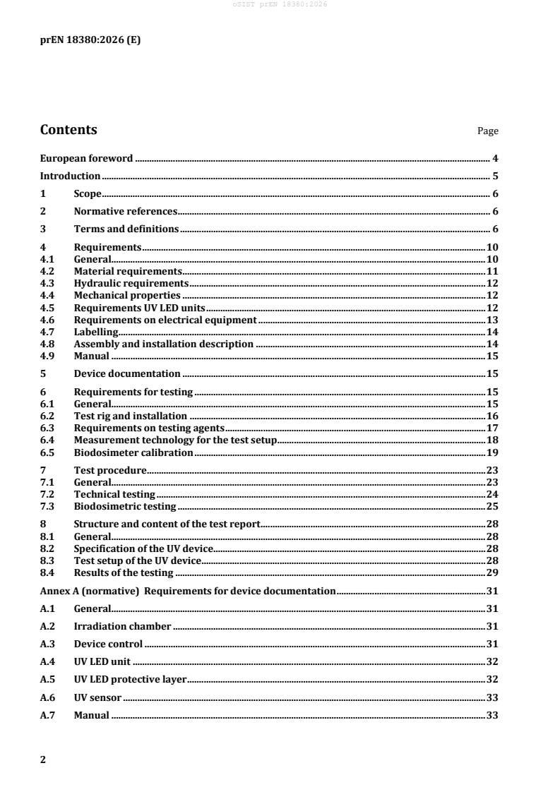
prEN 18380 is a CEN draft European Standard for water conditioning equipment inside buildings that use ultraviolet light-emitting diode (UV LED) units. It specifies performance, safety and testing requirements for UV devices used in potable water installations, with a focus on the UV reactor and the evidence needed to validate its treatment performance.
The standard is intended for manufacturers, test laboratories, installers, and specifiers who need to select, build, document, test, or approve UV LED water treatment devices for building water systems.
What does prEN 18380 specify?
prEN 18380 specifies definitions, construction principles, performance requirements, and test methods for UV devices with nominal UV wavelengths from 240 nm to 290 nm. It applies to potable water installations according to EN 806-2, including devices at the point of entry (POE), within the building distribution system, and at the point of use (POU), and it also allows use in mobile or temporary potable water installations.
The document is organized into:
- Clause 1 Scope
- Clause 2 Normative references
- Clause 3 Terms and definitions
- Clause 4 Requirements
- Clause 5 Device documentation
- Clause 6 Requirements for testing
- Clause 7 Test procedure
- Clause 8 Structure and content of the test report
- Annex A device documentation requirements
- Annex B collimated beam irradiation apparatus
| Annex | What it covers |
|---|---|
| Annex A | The documentation package for the device, including drawings, data sheets, type plate information, control system details, UV LED unit data, protective layer data, sensor data, and the manual |
| Annex B | The collimated beam irradiation apparatus and the method used to determine Petri factor and to expose biodosimeter samples |
The standard relates solely to the performance of the UV reactor. That matters in practice because upstream or downstream treatment elements are not credited in the performance claim.
What are the key requirements of prEN 18380?
prEN 18380 sets out the main design, labeling, and type-test conditions needed to validate a UV LED device for potable water use. The most important points are the performance categories, the water-quality basis for validation, the physical and electrical safeguards, and the biodosimetric test method used to prove treatment effect.
Performance categories and validated fluence
Clause 4.1 divides devices into Category A and Category B. Category A is for disinfection and Category B is for microbial control, with different reduction equivalent fluence (REF) targets at 254 nm.
In practice, this means the manufacturer must declare the category and validate the device at the matching flow rate and UV transmittance (UVT) range. The test result is not just a pass/fail on hardware - it ties the device to a specific operating window.
Materials, hydraulics, and mechanical integrity
Clauses 4.2 to 4.4 require UV-exposed parts to be UV resistant and corrosion resistant where relevant, and all potable-water contact materials to be suitable for drinking water use. The device also needs a flow limiter or host-system control so the validated maximum flow rate is not exceeded.
Mechanically, the device must withstand pressure-related checks, including hydrostatic and cyclic pressure resistance, and it must prevent direct or indirect UV leakage below 400 nm. For a buyer or installer, this is the part that tells you whether the unit is built for the system pressure and can be installed safely.
UV LED unit performance and lifetime
Clause 4.5 requires the UV LED spectrum to have a unimodal peak in the range 240 nm to 290 nm. It also requires the maximum operating hours to be stated on the type plate and in the manual, and it allows validation at different operating points, including dimmed operation if the conditions are clearly defined.
This matters because the device may be approved only for the validated UVT and flow-rate combinations, and any lower-power mode has to be declared if it sits outside that validated window.
Electrical control, monitoring, and alarm functions
Clause 4.6 requires a controller that starts or maintains operation when water flows, records operating hours, monitors UV LED function, signals low-UV conditions, and provides a general malfunction signal. The device must also provide an optical sensor or be compatible with a host system that does the same job.
The practical meaning is that the device must be able to warn the user when output drops or water quality changes beyond the validated range, and it must allow the water flow to be stopped when treatment is no longer adequate.
Labeling, installation information, and manual
Clauses 4.7 to 4.9 require a durable type plate, installation instructions, and a manual. The label must include the manufacturer, type designation, year, serial number, category, water quality, maximum flow rate, pressure rating, maximum operating hours, and certification information.
The manual must describe installation, operation, cleaning, service, operating range, flow direction, electrical data, temperature limits, humidity limit, and the validated flow-rate limit for the stated water quality. In practice, these are the details a user or service technician needs to install the unit correctly and keep it within its tested envelope.
Testing, biodosimetry, and report content
Clauses 6 and 7 define the type test. The device is tested at end-of-life derated output, with flow rate and UVT set to the manufacturer’s claimed conditions, and the performance is measured by biodosimetric testing using MS2 bacteriophage as the surrogate microbe.
This means the claimed UV treatment is not based only on lamp power or sensor readings. It is backed by challenge testing, control measurements, and a calculated REF for each operating point. Clause 8 then requires a written report with device identification, test setup, calibration details, biodosimeter data, test water characterization, and the technical and biodosimetric results.
What terms does prEN 18380 define?
prEN 18380 defines the vocabulary used to describe UV treatment performance and testing.
- Reduction equivalent fluence (REF) - the average germicidal fluence measured with the biodosimeter, used to back-calculate UV treatment performance.
- UV transmittance (UVT) - the spectral transmission rate of water at 254 nm over a 10 mm path length, expressed as a percentage.
- Irradiance - UV light flux divided by the area receiving it; the sensor reading influenced by lamp output, water UVT, fouling, and geometry.
- Biodosimeter - the surrogate microbe used to determine REF; in this document, MS2 phage is used.
- UV LED unit - a grouped set of UV LEDs that produces UV light.
- Radiation chamber - the part of the device containing the radiation zone and connecting pipes through which the water flows.
- Permissible operation range - the flow-rate and irradiance or UVT limits where adequate treatment is assured.
Who uses prEN 18380?
prEN 18380 is used by manufacturers of UV LED water treatment devices, especially those designing POE and POU products for potable water systems. It is also used by test laboratories that perform type testing, calibration, and biodosimetric validation.
Installers and system integrators use it to understand the installation conditions, flow direction, pressure limits, and control requirements. Quality managers, certifiers, and buyers use it to check whether a device has the right documentation, test evidence, and declared operating window for a given application.
Which standards are used with prEN 18380?
prEN 18380 cites EN 10253 (all parts) as a normative reference for butt-welding pipe fittings, which supports the test-rig installation details, including the 90° bend ahead of the device.
The body and bibliography also reference:
- EN 806-2 - the building water installation context for potable water systems
- EN 14743 - the cyclic pressure test reference
- EN ISO 10705-1 - the method used for MS2 phage enumeration
- EN ISO/IEC 17025 - the competence basis for testing and calibration laboratories, also referenced for certification on the type plate
These references tell the reader which related standards support the installation, pressure testing, microbiological method, and laboratory competence used with this document.
What does the prEN 18380 document contain?
prEN 18380 contains category definitions, material and mechanical requirements, electrical monitoring requirements, labeling rules, and the document set that must accompany the device. It also includes a detailed test rig arrangement, water-quality requirements for the test water, and calibration rules for the UV-Vis spectrophotometer, flow measurement, temperature measurement, and irradiance measurement.
The document goes further into biodosimeter preparation, collimated beam irradiation, and the calculation of fluence and log inactivation. Figures 1 to 3 and Annex B support the apparatus setup and Petri factor method, while Tables 2 to 7 define the validation ranges, test-result templates, and reporting format.
Get Certified
Connect with accredited certification bodies for this standard

DIBt (Deutsches Institut für Bautechnik)
German Institute for Building Technology.
DIN CERTCO
DIN Group product certification.

Aboma Certification B.V.
Specialized in construction, metal, and transport sectors.
Sponsored listings
Frequently Asked Questions
prEN 18380 is a draft published by the European Committee for Standardization (CEN). Its full title is "Water conditioning equipment inside buildings - Devices using UV LED units - Requirements for performance, safety and testing". This standard covers: This document specifies definitions, principles of construction, requirements and methods for testing the performance of UV devices (240 nm to 290 nm nominal) for potable water installations according to EN 806-2 which are permanently connected to the building’s supply. Devices described by this document can be installed at the point of entry (POE), within the water distribution system inside the building or at the point of use (POU). Additionally, the devices described in this document can be used in mobile or temporary potable water installations, where the system is not permanently connected to a water supply. UV devices in the sense of this document are UV bactericidal treatment devices or UV disinfection devices for one of three specified water qualities, determined by the observed UV transmittance. Devices can be standalone, integrated into a larger appliance or part of multi-staged treatment process. The document relates solely to the performance of the UV reactor.
This document specifies definitions, principles of construction, requirements and methods for testing the performance of UV devices (240 nm to 290 nm nominal) for potable water installations according to EN 806-2 which are permanently connected to the building’s supply. Devices described by this document can be installed at the point of entry (POE), within the water distribution system inside the building or at the point of use (POU). Additionally, the devices described in this document can be used in mobile or temporary potable water installations, where the system is not permanently connected to a water supply. UV devices in the sense of this document are UV bactericidal treatment devices or UV disinfection devices for one of three specified water qualities, determined by the observed UV transmittance. Devices can be standalone, integrated into a larger appliance or part of multi-staged treatment process. The document relates solely to the performance of the UV reactor.
prEN 18380 is classified under the following ICS (International Classification for Standards) categories: 91.140.60 - Water supply systems. The ICS classification helps identify the subject area and facilitates finding related standards.
prEN 18380 is available in PDF format for immediate download after purchase. The document can be added to your cart and obtained through the secure checkout process. Digital delivery ensures instant access to the complete standard document.
Standards Content (Sample)
SLOVENSKI STANDARD
01-oktober-2026
Oprema, ki se uporablja za pripravo pitne vode v stavbah - Naprave, ki uporabljajo
enote UV LED - Zahteve za delovanje, varnost in preskušanje
Water conditioning equipment inside buildings - Devices using UV LED units -
Requirements for performance, safety and testing
Wasserbehandlungsgeräte in Gebäuden - Geräte mit UV-LED-Strahlereinheiten -
Anforderungen an Leistung, Sicherheit und Prüfung.
Équipement de conditionnement de l'eau à l'intérieur des bâtiments - Dispositifs utilisant
des unités LED UV - Exigences en matière de performance, de sécurité et d'essais
Ta slovenski standard je istoveten z: prEN 18380
ICS:
13.060.20 Pitna voda Drinking water
91.140.60 Sistemi za oskrbo z vodo Water supply systems
2003-01.Slovenski inštitut za standardizacijo. Razmnoževanje celote ali delov tega standarda ni dovoljeno.
DRAFT
EUROPEAN STANDARD
NORME EUROPÉENNE
EUROPÄISCHE NORM
August 2026
ICS 91.140.60
English Version
Water conditioning equipment inside buildings - Devices
using UV LED units - Requirements for performance, safety
and testing
Équipement de conditionnement de l'eau à l'intérieur Wasserbehandlungsgeräte in Gebäuden - Geräte mit
des bâtiments - Dispositifs utilisant des unités LED UV - UV-LED-Strahlereinheiten - Anforderungen an
Exigences en matière de performance, de sécurité et Leistung, Sicherheit und Prüfung.
d'essais.
This draft European Standard is submitted to CEN members for enquiry. It has been drawn up by the Technical Committee
CEN/TC 164.
If this draft becomes a European Standard, CEN members are bound to comply with the CEN/CENELEC Internal Regulations
which stipulate the conditions for giving this European Standard the status of a national standard without any alteration.
This draft European Standard was established by CEN in three official versions (English, French, German). A version in any other
language made by translation under the responsibility of a CEN member into its own language and notified to the CEN-CENELEC
Management Centre has the same status as the official versions.
CEN members are the national standards bodies of Austria, Belgium, Bulgaria, Croatia, Cyprus, Czech Republic, Denmark, Estonia,
Finland, France, Germany, Greece, Hungary, Iceland, Ireland, Italy, Latvia, Lithuania, Luxembourg, Malta, Netherlands, Norway,
Poland, Portugal, Republic of North Macedonia, Romania, Serbia, Slovakia, Slovenia, Spain, Sweden, Switzerland, Türkiye and
United Kingdom.
Recipients of this draft are invited to submit, with their comments, notification of any relevant patent rights of which they are
aware and to provide supporting documentation.
Warning : This document is not a European Standard. It is distributed for review and comments. It is subject to change without
notice and shall not be referred to as a European Standard.
EUROPEAN COMMITTEE FOR STANDARDIZATION
COMITÉ EUROPÉEN DE NORMALISATION
EUROPÄISCHES KOMITEE FÜR NORMUNG
CEN-CENELEC Management Centre: Rue de la Science 23, B-1040 Brussels
© 2026 CEN All rights of exploitation in any form and by any means reserved Ref. No. prEN 18380:2026 E
worldwide for CEN national Members.
Contents Page
European foreword . 4
Introduction . 5
1 Scope . 6
2 Normative references . 6
3 Terms and definitions . 6
4 Requirements . 10
4.1 General. 10
4.2 Material requirements . 11
4.3 Hydraulic requirements . 12
4.4 Mechanical properties . 12
4.5 Requirements UV LED units . 12
4.6 Requirements on electrical equipment . 13
4.7 Labelling . 14
4.8 Assembly and installation description . 14
4.9 Manual . 15
5 Device documentation . 15
6 Requirements for testing . 15
6.1 General. 15
6.2 Test rig and installation . 16
6.3 Requirements on testing agents . 17
6.4 Measurement technology for the test setup . 18
6.5 Biodosimeter calibration . 19
7 Test procedure . 23
7.1 General. 23
7.2 Technical testing . 24
7.3 Biodosimetric testing . 25
8 Structure and content of the test report . 28
8.1 General. 28
8.2 Specification of the UV device. 28
8.3 Test setup of the UV device . 28
8.4 Results of the testing . 29
Annex A (normative) Requirements for device documentation . 31
A.1 General. 31
A.2 Irradiation chamber . 31
A.3 Device control . 31
A.4 UV LED unit . 32
A.5 UV LED protective layer . 32
A.6 UV sensor . 33
A.7 Manual . 33
Annex B (normative) Apparatus for collimated beam irradiation . 34
Bibliography . 38
European foreword
This document (prEN 18380:2026) has been prepared by Technical Committee CEN/TC 164 “water
supply”, the secretariat of which is held by AFNOR.
This document is currently submitted to the CEN Enquiry.
Introduction
A non-exhaustive list of potential applications of products described in this document:
— upstream microbiological control ahead of water softeners, or treatment processes which remove a
residual disinfectant (e.g. activated carbon);
— within commercial drinks dispensers as a final polishing/assurance stage;
— as a point of entry system where the municipal supply may be at risk of recontamination within
distribution or interruption of sufficient disinfection at source;
— Legionella control in hot water loops.
1 Scope
This document specifies definitions, principles of construction, requirements and methods for testing the
performance of UV devices (240 nm to 290 nm nominal) for potable water installations according to
EN 806-2 which are permanently connected to the building’s supply.
Devices described by this document can be installed at the point of entry (POE), within the water
distribution system inside the building or at the point of use (POU).
Additionally, the devices described in this document can be used in mobile or temporary potable water
installations, where the system is not permanently connected to a water supply.
UV devices in the sense of this document are UV bactericidal treatment devices or UV disinfection devices
for one of three specified water qualities, determined by the observed UV transmittance.
Devices can be standalone, integrated into a larger appliance or part of multi-staged treatment process.
The document relates solely to the performance of the UV reactor.
2 Normative references
The following documents are referred to in the text in such a way that some or all of their content
constitutes requirements of this document. For dated references, only the edition cited applies. For
undated references, the latest edition of the referenced document (including any amendments) applies.
EN 10253 (all parts), Butt-welding pipe fittings
3 Terms and definitions
For the purposes of this document, the following terms and definitions apply.
ISO and IEC maintain terminology databases for use in standardization at the following addresses:
— ISO Online browsing platform: available at https://www.iso.org/obp/
— IEC Electropedia: available at https://www.electropedia.org/
3.1
absorption
reduction in radiant energy or power, including transformation to other forms, e.g. heat, chemical, as a
ray passes through or impinges upon a material
Note 1 to entry: Expressed in J or W, as appropriate.
3.2
irradiance
measure of the UV light flux divided by the area that intercepts the radiation
Note 1 to entry: The irradiance measured in UV disinfection devices by the UV device sensor is mainly influenced
by the lamp output, the transmittance of the water, scaling/fouling of the protective window, and the position of the
lamp(s) and sensor in the radiation chamber.
Note 2 to entry: Expressed in W/m .
3.3
disinfection
action of killing or inactivating relevant bacteria, viruses, and spores to a specified degree of at least
99,99 % using a UV disinfection device
Note 1 to entry: Verification of reduction rates is done by biodosimetric testing on surrogate microbes.
3.4
fluence
dose, product of irradiance and exposure time
Note 1 to entry: Fluence is the correct term from a strictly scientific point of view.
Note 2 to entry: Fluence is expressed in J/m .
3.5
reduction equivalent fluence
REF
average germicidal fluence measured using the biodosimeter
Note 1 to entry: Expressed in J/m .
Note 2 to entry: Use of a low pressure mercury discharge lamp as reference gives a value for a relative exposure at
254 nm; REF (254 nm).
3.6
radiation chamber
part of the device that comprises the radiation zone and the connecting pipes, though which the water to
be treated flows
3.7
radiation zone
part of the radiation chamber whose volume is used for the calculation of the fluence
3.8
exposure time
volumetric mean
time interval during which a specific volume of water within the radiation zone is exposed to the radiation
3.9
microbial dosimeter;
biodosimeter, surrogate
test microbe used to determine the reduction equivalent fluence, whose UV inactivation behaviour has
been determined in a standard collimated beam apparatus
Note 1 to entry: In the case of this document, MS2 phage (ATCC 15597-B1).
3.10
minimum irradiance
UV sensor value determined in the type test that ensures the required reduction equivalent fluence at a
defined water flow rate and at a defined UV transmittance value
Note 1 to entry: Expressed in W/m .
3.11
flow rate
Q
volume of water per unit time flowing through the UV device
Note 1 to entry: Expressed in l/min or m /h.
3.12
maximum flow rate
Q
max
highest flow at which, at a defined UV transmittance of the water and a defined irradiance, the required
reduction equivalent fluence can be guaranteed
Note 1 to entry: Expressed in l/min or m /h.
3.13
permissible operation range
those limit values for the operation parameters (irradiance at the sensor or UV transmittance of the
water) and flow rate where adequate bactericidal treatment or disinfection is assured
3.14
sensor
system for the measurement of the relative irradiance in UV disinfection devices
Note 1 to entry: A relative signal may be used and calibration to an absolute irradiance [W m-2] is not required.
3.15
attenuation
total reduction in transmission (absorption and scattering) of radiation passing through an optical
medium in a specific direction
3.16
lamp service life
service life of a UV LED unit after which the emission that is necessary to guarantee the minimum fluence
can no longer be reached under the mode of operation given by the manufacturer
3.17
UV LED unit
grouped UV LEDs which produces UV light
3.18
UV LED device
general expression for products using UV light to irradiate water flow through, with the purpose of
inactivating microbes present in the water
3.19
UV LED disinfection device
device designed to disinfect water
Note 1 to entry: Category A device.
3.20
UV LED bactericidal treatment device
device designed for bactericidal water treatment
Note 1 to entry: Category B device.
3.21
turbidity
reduction of transmittance of visible wavelengths through a liquid caused by the presence of suspended
matter (via scattering or scattering and absorption)
Note 1 to entry: Turbidity is not directly related to UV transmittance.
3.22
UV transmittance
% UVT
spectral transmission rate at a wavelength of 254 nm at an optical path length in the medium of 10 mm,
in %.
Note 1 to entry: UVT100 is a similar metric, scaled for an optical path length of 100 mm.
Note 2 to entry: In general, the UV transmittance includes the influence of scattering and absorption of the medium.
The UV transmittance is measured in the unfiltered sample in quartz cuvettes of at least 40 mm at a wavelength of
254 nm in a spectrophotometer and is given in %.
3.23
UV radiation
UV
electromagnetic radiation
Note 1 to entry: Table 1 shows different wavelengths of UV radiation and their classification:
Table 1 — UV radiation
Wavelength
Type
nm
UV-C > 100 ≤ 280
UV-B > 280 ≤ 315
UV-A > 315 ≤ 400
NOTE For bactericidal and disinfection purposes, part of the UV range is used.
3.24
modal peak wavelength
wavelength at which the UV LED device emits its highest intensity radiation
Note 1 to entry: I.e. at the peak of a spectral emission curve, expressed in nm.
3.25
spectral full-width half-maximum
FWHM
measure of the breadth of an LED emission spectrum, taken as the width of the spectrum, at 50 % of the
relative intensity
3.26
sampling event
action of drawing a sample of the test water from one of the sampling ports or a holding tank, within the
biodosimetric testing phase
3.27
measurement point
set of operational conditions under which samples of the test water are drawn; multiple sampling events
occur at a single measurement point, within the biodosimetric testing phase
4 Requirements
4.1 General
This document covers two different categories of UV LED devices. The categories differ in terms of their
validated fluence delivery, at a specified flow rate and water quality, resulting in differences in the
associated microbiological treatment of the water leaving the reactor.
Both performance Categories A and B are intended to provide a pathogen barrier and maintain the user’s
health, though the degree of treatment varies between the two based on the intent of the application. A
distinction is drawn between the two treatment levels as follows:
— Category A provides disinfection at a fluence known to be sufficient where no primary antimicrobial
treatment has been applied upstream; waters of uncertain origin, influence, or where treatment is
known not to exist upstream should be treated to this level.
— Category B provides microbial control at a fluence intended as a secondary or higher treatment stage
to water which has otherwise undergone disinfection; water which may be subject to
incidental/retrograde contamination in distribution, stagnation, or microbial regrowth after
otherwise sufficient disinfection should be treated to this level.
This document primarily considers systems whose main function is the treatment of water by UV
irradiation and though an integrated system may be considered, the following distinctions hold:
— Water quality is defined as that which enters the UV disinfection portion of the system, which may
not necessarily be the inlet port of a host system to the UV device, and the effect of upstream
modifications to the water quality within the system may be considered when defining the UV LED
device inlet water quality.
— Assessment of disinfection/antimicrobial effect will only consider the action of the UV LED device,
with no ‘credit’ ascribed to upstream processes.
Table 2 — Categories for different performance claims
Category A B
Performance Disinfection Microbial Control
claim
2 2
Reduction 400 J/m 250 J/m
Equivalent
Fluence
(254 nm)
Optical yes yes
Sensor
Water Quality 70 % to 85 % 85 % to >95 % 70 % to 85 % 85 % to >95 %
UV 95 % 95 %
transmittance
(UVT ) range
Descriptive Raw water with Raw water Very high Treated water with Typical Very high
water quality unknown of high quality, an otherwise high municipal quality,
microbiological quality or requiring concentration of potable typically
quality but having additional dissolved/suspended water municipal
without an undergone disinfection material potable
obvious source some pre- for water with
of treatment exceptional additional
contamination conditions treatment
at the
installation
(e.g. Active
Carbon,
Reverse
Osmosis)
The water quality descriptions provided here are intended to be descriptive of common use cases, but
not at all limiting to the final application.
Determination of the appropriate Category and Water Quality of the UV systems validated to this
document for a given applications should be considered based on the provenance of the water and an
observed UVT. Selection of the appropriate water quality should be made such that the observed UVT
falls within that range, with the test condition representing the worst-case for that range.
Since this document considers water of "drinking water quality” (according to [1]), then other parameters
not described (e.g. chemical composition, turbidity, etc.) are considered to be sufficiently within range to
render the source water potable, except for the potential for microbiological contamination which this
document aims to address.
4.2 Material requirements
All components in contact with UV radiation shall be made of corrosion resistant (if applicable) and UV
resistant materials. All materials in contact with potable water shall be suitable for that use.
NOTE European and national regulation(s) can apply.
4.3 Hydraulic requirements
All devices shall be equipped with a flow limiter to ensure that the maximum flow rate, as defined by the
manufacturer, is not exceeded. The flow limiter shall operate in a pressure range, as described by the
manufacturer. Alternately, flow limitation or control may be deferred to a host system to maintain the
validated maximum flow rate.
The flow limiter is not subject to the testing-schemes described in this document.
4.4 Mechanical properties
4.4.1 General
The mechanical design and the construction shall comply with the relevant requirements for the pressure
range, as specified by the manufacturer.
Direct or indirect leaking of radiation from the radiation chamber to the environment with a wavelength
<400 nm shall be avoided.
4.4.2 Resistance to pressure
4.4.2.1 Resistance to hydrostatic pressure
The UV device may be exposed to a hydrostatic pressure of 1,5 times the maximum design pressure or
10 bar, whichever is the higher pressure, for a period of 10 (+2/-0) min without visible damage or leaks.
4.4.2.2 Resistance to cyclic pressure
The UV device shall not fail a cyclic pressure test after less than 5 000 cycles with a pressure cycle
frequency of 15 (+2/-1) cycles per minute between 1,5 bar and 1,3 times the maximum design pressure,
as specified by the manufacture, show neither visible damage nor leaks (see EN 14743).
4.5 Requirements UV LED units
4.5.1 Radiation
UV spectrum of the device for the purposes of water irradiation shall match that of a typical LED array,
with a unimodal peak in the range 240 nm to 290 nm, thus preventing photochemical effects that may
result from shorter wavelengths and potential algae growth stimulated by longer wavelengths.
4.5.2 Lifetime
Performance of the UV device is majority governed by the duration for which the UV LED unit is active,
and not the installed duration.
Manufacturers may make individual operating lifetime claims based on the performance characteristics
and design of the system. Maximum operating hours for the UV LED lamp unit shall be indicated on the
type plate and in the manual.
Performance testing shall be conducted on UV-LED devices artificially ‘aged’ according to manufacturers’
specification of end-of-life relative output, see 7.2.6.
4.5.3 Operation
Devices can be validated with different operating points (UVT vs. Q), these shall be verified by the type
test accordingly.
Devices that allow operation at dimmed radiant power (e.g. at lower flow rates for the purpose of energy
efficiency or life extension), can be used. Such devices shall either have additional operational points
within the type test or shall clearly state within the manual and type plate the conditions of this mode
which are outside of the validated operating window of the device.
Devices intended to be operated in systems with elevated water temperatures (>25 °C) shall specify the
maximum acceptable water temperature in the manual and on the type plate. The materials used shall
ensure hygiene suitability and mechanical stability of the device for the intended operational
temperature range.
4.6 Requirements on electrical equipment
4.6.1 General
Requirements for the electrotechnical design of UV devices are regulated by the relevant EC Directives.
The IP rating shall be indicated.
4.6.2 Controller
The UV disinfection device shall be equipped with a controller, which provides the following functions:
— when water starts to flow, the device shall be switched on immediately upon flow exceeding the
stated initialization flow rate; alternately, the device could be in continual operation;
— operation of the electrical function of UV LED units shall be monitored;
— total UV LED unit operating hours shall be recorded;
— operation beyond the permissible limits of operation (UV-intensity too low) shall be indicated and a
signal shall be provided which allows the waterflow to be stopped;
— general malfunction signal shall be provided.
The following functions shall be displayed:
— device operational: on/off;
— general malfunction.
Alternatively, the UV disinfection device shall be compatible with the above functionality as supported
by a host system, and these functions need not be provided exclusively by the UV disinfection device.
4.6.3 Sensor
For the measurement of irradiation within the device, an optical sensor shall be provided to ensure
sufficient fluence delivery under consideration of possible changes in water UV transmittance and UV
LED unit performance.
The approach here is to define a minimum UV alarm set point; this shall be set as the UV sensor signal at
the challenge UVT of the test and for a UV source artificially aged according to 7.2.6. The alarm shall
trigger if the UV sensor reads a value below this threshold, signifying a drop in UV power (below end of
life output) or reduction in UVT below the validated range. Therefore, in the majority of conditions (as
new LED source, higher UVT) the system shall provide a fluence in excess of the validated minimum. The
control system shall be calibrated on the relative irradiance recorded by the sensor. The sensor shall be
located in a way that the UV LEDs can be monitored appropriately and is not unduly disturbed by gas
bubbles or sediment deposits. The sensor shall be located with the UV source, adjacent, opposite, or
otherwise, but shall have sufficient sensitivity to the emissions of the source and be able to sense a change
in UVT of the water.
Additional considerations for the UV sensor:
— the sensitivity range of the sensor should be appropriate to the device as new and under an end of
life condition;
— absolute irradiance calibration of the sensor is not required;
— absolute sensor signals can therefore differ between devices, with interpretation by a control
system accounting for relative response;
— if a sensor with absolute irradiance calibration is used, then sufficient evidence shall be provided
to support the validity and calibration of an absolute irradiance determination;
— control system should read “100 %” as new, and have sufficient range to show lowest UVT and or UV
output in derated modes and or end of life;
— sensors are typically coupled to the LED array in such a way that if one is required to be replaced that
the other is also be replaced, if either or both are replaced the system shall undergo recalibration as
initially conducted in device production;
— the sensor should exhibit a stable response over the lifetime of the product as described by the
system manufacturer; not exceeding a +5% increase over that lifetime for an equivalent irradiance.
4.7 Labelling
A type plate with the following minimum information shall be attached to the irradiation chamber:
— manufacturer;
— address of the manufacturer;
— type designation of the UV device;
— year of manufacture;
— serial number;
— category and water quality (according to Table 2);
— maximum flow rate;
— pressure rating/operating pressure;
— maximum operating hours;
— certification (based on tests by competent laboratories, e.g. according to EN ISO/IEC 17025).
The material of the type plate, including the lettering and the fastening, shall be durable and waterproof.
4.8 Assembly and installation description
Installation instructions with all the necessary information for the correct energy connection and for the
required control and safety circuits (if applicable).
Installation description with details of the flow direction, installation dimensions, installation position
and the requirements for the inlet and outlet sections, taking into account shut-off devices and any other
piping components (if applicable).
4.9 Manual
Operating instructions for the UV device shall be prepared and shall contain at least the following
information:
Technical description:
— dimensions, installation dimensions and technical characteristics;
— nominal pressure, nominal flow rate, indication of flow direction;
— electrical supply voltage, frequency, rated current, rated power consumption, IP class;
— circuit diagram;
— functional description of the control unit if applicable;
— min/max ambient temperature;
— min/max water temperature;
— maximum ambient humidity;
— maximum operating hours.
The manual shall describe operation, control, cleaning and service measures.
The manual shall also contain at least the following information:
— permitted operating range, maximum validated flow rate for the stated water quality and category.
This may be stated as a single condition or as a matrix/table, depending on the validated conditions.
5 Device documentation
Device documents shall be provided as outlined in Annex A (normative).
6 Requirements for testing
6.1 General
The details and device documentation described in Annex A shall be provided. The device under test is
checked for conformity to the documentation.
The purpose of the type test is to verify that the UV fluence delivered by the device under test meets a
reduction equivalent fluence in accordance to the desired category and water quality described in Table 2
at the end of the UV LED unit life and at the specified flow rates as described by the manufacturer.
Performance of the UV LED unit only shall be assessed, with any upstream/downstream water
conditioning/treatment elements bypassed for the purposes of testing, if required.
Parameters to be changed during testing are the flow rate, the UV transmittance and the output of the UV
LED unit (if applicable, see 4.5.3) for the test of UV disinfection devices.
The UV device to be tested shall be fitted with UV lamps with a de-rated output in accordance with 7.2.6,
representing an end-of-life condition, and is to be assessed without a mandatory ‘burn in’ phase, unless
specified by the manufacturer within the product manual.
6.2 Test rig and installation
A test rig is required for the biodosimetric tests, which shall consist of the following components as listed
below:
— test water supply with flow control device;
— dosing devices for the uniform, pulsation-free addition of test organisms and UV-absorbing
substances;
— mixing devices for uniform distribution of the additives in the inlet to the UV LED device;
— sampling point between the mixing device and the installation section of the test sample;
— installation section for the test sample with 90° bend directly in front of the UV LED device;
— measuring technology for continuous recording and registration of the test water flow, UV
transmission and temperature of the test water, irradiance, supply voltage;
— (static) mixing device after the installation section;
— sampling point after the mixing device;
— waste water discharge;
— optional: differential pressure measurements to determine the pressure loss of the UV device.
Key
1 test water inlet check valve 9 pressure measurement device
2 flow adjustment valve 10 temperature measurement device
3 UVT modifier dosing pump 11 upstream sampling port
4 biodosimeter stock dosing pump 12 flowmeter
5 UVT modifier source 13 downstream static mixer
6 biodosimeter stock source 14 downstream sampling port
7 upstream static mixer 15 stop valve
8 UVT measurement device
Figure 1 — Example setup of a test rig
The following requirements shall also be met:
The test water shall meet the requirements according to 6.3.1, be available in sufficient quantity and at a
constant pressure and temperature to flow through the test stand.
The wastewater produced during the test shall be disposed in accordance with local requirements, if
necessary, with special approval.
Dosing and mixing equipment shall ensure the constant and reproducible mixing of the biodosimeters
and the transmission-reducing substance for all test points at the associated test water flow rates. Dosing
devices shall therefore operate with low pulsation (dosing consistency < ± 2 %).
An optional apparatus may draw from a tank/batch of prepared test water, with challenge microbe and
UVT modifier added and homogenized prior to injection into the test device.
For either set-up, the mixing consistency of the biodiosimeter shall be achieved as described in 6.5.2.
The test sample shall be installed in the installation section directly behind a 90° pipe bend (design or
type 3D according to EN 10253-1, EN 10253-2, EN 10253-3 or EN 10253-4) in order to take unfavourable
hydraulic conditions into account during the test.
Only materials approved for potable water applications shall be used for all components of the test rig in
contact with potable water.
All components of the test rig shall be made of corrosion resistant (if applicable) and UV resistant
materials. All materials shall be suitable for contact with water intended for human consumption (see
[1]).
NOTE European and national regulation(s) can apply.
The sampling points shall be made of flame-resistant metal with a straight outlet pipe to ensure proper
microbiological sampling. The sampling points shall be arranged in such a way that the required mixing
quality is achieved at the sampling location and no UV radiation of the test sample is effective.
The metrological equipment of the test stand shall meet the requirements of 6.4.
Electrical equipment shall comply with the relevant standards and regulations. The installation shall be
secured in accordance with the local occupational health and safety rules.
6.3 Requirements on testing agents
6.3.1 Test water
Test water is the water for testing the UV device after adding the biodosimeter and, if necessary,
transmission-reducing substances. The test water shall not contain a biodosimeter that has already been
irradiated.
6.3.2 Transmission-reducing substance
The UV transmission of the test water is to be adjusted with an aqueous humic acid (e.g. Superhume or
equivalent).
The target UV transmission for a given test condition is taken as the lower end of the range stated in
Table 2; the transmission-reducing substance shall be dosed to the test water such that the observed UV
transmittance does not exceed the target value when rounded to the nearest 1 %.
6.3.3 Water for the preparation of the test water
The water used to prepare the test water shall be of potable water quality and have a sufficiently high
UVT 10 for setting the test conditions as well as the properties listed in Table 3. Disinfectants shall not be
detectable.
Table 3 — Properties of the water for preparation of the test water
Parameters Requirements
Temperature 5 °C to 20 °C
UVT 10 (254 nm) ≥98,00 %
Iron ≤0,2 mg/l
Manganese ≤0,05 mg/l
Turbidity ≤0,2 NTU
Colony count at 22 °C ≤100 CFU/ml
Escherichia coli 0 CFU/100 ml
Enterococci 0 CFU/100 ml
6.3.4 Transmission measurement
The UVT10 is measured using quartz cells with a path length of at least 40 mm. For UVT10 values less
than 74,1 %, the measurement is carried out using quartz cells with a path length of 10 mm.
6.4 Measurement technology for the test setup
6.4.1 UV-Vis spectrophotometer
To ensure the functionality of the spectrophotometer, the wavelength accuracy and photometric accuracy
(specific absorption) shall be checked at least once a year using state-of-the-art materials (e.g. solutions
of holmium perchlorate and potassium dichromate or filters) or this shall be carried out by a specialist
company. In addition, the specific absorption of a solution of potassium dichromate or a suitable filter
shall be measured every six months.
6.4.2 Requirements for ultrapure water for calibrating the photometer
The ultrapure water is the 100 % reference for measuring the transmission of the water samples to be
analysed. To determine the suitability, the spectrum of the ultrapure water shall be recorded in a 100 mm
quartz cuvette against air. At a wavelength of 254 nm, the UVT100 of the ultrapure water shall be at least
88 %. At a wavelength of 220 nm, the UVT100 of the ultrapure water shall be at least 84 %.
6.4.3 Flow measurement
The flow measurement shall be carried out using magnetic induction or ultrasound.
The arrangement of the measuring device for recording the test water flow rate shall be in accordance
with the specifications of the measuring device manufacturer. The measurement uncertainty of the flow
measurement shall not exceed ±2 %.
6.4.4 Temperature measurement
The water temperature shall be continuously measured and recorded with a measurement uncertainty
of ±0,5 °C.
6.4.5 Measurement of power consumption of the UV LED device
The supply voltage, current and active power shall be measured and recorded continuously.
The following applies to the measurement uncertainty:
— Voltage and current: maximum ±1 % of the measured value;
— Active power: maximum ±1,5 % of the measured value.
6.4.6 Irradiance measurement during collimated beam characterization of biodosimeter
For the biodosimetric stage of testing, a radiometer is required to calibrate the collimated beam
-2 -2
apparatus. This device should have sufficient sensitivity in the range of interest (0,01 W m to 100 W m )
and be calibrated as traceable against a national standard for absolute irradiance at 254 nm. Calibration
should be maintained at a maximum interval of 1 year prior to the date of test.
6.5 Biodosimeter calibration
6.5.1 General information
The objective of this test is to establish an inactivation response of the biodosimeter (challenge microbe)
to be used in the UV function technical tests of 7.3. The apparatus described here provides a uniform
exposure to a sample of the biodosimeter microbe within a neutral suspension matrix; homogeneity of
the exposure is ensured by the apparatus design and test methodology.
Recommendations in [2] should be heeded in the case of uncertainty in experimental design. This method
is explicitly intended for the use of cylindrical mercury vapour discharge lamps as the UV source; no other
source types are considered for the biodosimetry calibration. Consequently, the calculated reduction
equivalent fluence (REF) is that at a monochromatic 254 nm.
MS2 bacteriophages (ATCC 15597-B1) are to be used as biodosimeters. Escherichia coli (pFamp)R
(ATCC 700891) or Salmonella typhimurium (NCTC 12484) should be used as host bacteria for the
preparation. MS2 bacteriophages are prepared using either the single-layer or the double-layer plate
casting method. The single-layer method is described as 9224E in [4] and the double-layer method in
EN ISO 10705-1.
A description of the collimated beam apparatus set-up is provided in Annex B.
In the case that the MS2 biodosimeter is acquired from a suitably accredited lab and it provided with
appropriate data demonstrating compliance of the UV sensitivity of the phage with the bounds specified
in 6.5.4.4, then the phage may be considered compliant and these data used in lieu of testing per this
subclause.
More information on the MS2 action spectrum can be found in [5].
6.5.2 Preparation of the phage suspension
The phage stock suspension to be irradiated shall be made of water or buffered water (e.g. chlorine-free
tap water) with MS2 phage spiked to a target concentration of 5x10^5 PFU/ml and shall fall in the range
1x10^5 PFU/ml to 5x10^6 PFU/ml. To avoid settling of the suspension and minimize variation in each
sample drawn from the stock, it shall be mixed by magnetic stirrer through the duration of the experiment
6.5.3 UV inactivation curves
The UV sensitivity of a batch of phages shall be determined by inactivating them under laboratory
conditions. To determine the inactivation curve, samples of a suspension of the biodosimeter are exposed
in a Petri dish to a homogeneous radiation field of a quasi-parallel radiation of the wavelength 254 nm in
graduated fluences.
To calculate the REF of a UV device on the basis of the biodosimetric test according to 7.3, the standard
inactivation curve of the batch used shall be used.
The suitability of a biodosimeter batch can be determined in advance by comparison against the data
provided in 6.5.4.4.
6.5.4 Carrying out an inactivation
6.5.4.1 General
Sample irradiation for determination of the microbial sensitivity curve should follow several principles:
— after biodosimeter batch preparation, continuous mixing should be provided to avoid microbial
settling, and therefore irregular sampling;
— consistent volumes of the sample to be irradiated should be transferred to a sterile Petri dish for each
experimental point;
— exposures should be controlled via operation of a mechanical shutter to set exposure periods,
without intentional modification of the source output;
— the UV source should remain in thermal equilibrium throughout the period of testing, havin
...