

prEN 1930
(Main)Child care articles - Safety barriers - Safety requirements and test methods
- Abstract
This document specifies the safety requirements and test methods for child safety barriers for domestic indoor use.
This document does not apply to products designed to be fitted across windows.
If the safety barrier has other functions not covered in this document, the relevant European Standard(s) apply.
- Status
- Not Published
- Publication Date
- 01-Jul-2027
- Technical Committee
- CEN/TC 252 - Child use and care articles
- Drafting Committee
- CEN/TC 252/WG 4 - Early learning and protection
- Current Stage
- 4060 - Closure of enquiry - Enquiry
- Start Date
- 23-Jul-2026
- Due Date
- 06-Jan-2026
- Completion Date
- 23-Jul-2026



Overview
prEN 1930:2026 is a draft European Standard developed by the European Committee for Standardization (CEN) under the Technical Committee CEN/TC 252. The document specifies safety requirements and comprehensive test methods for child safety barriers used indoors in domestic environments. Its main objective is to ensure that child care articles like safety barriers-designed to limit children's access to certain parts of a home-are both reliable and safe. The standard applies specifically to barriers fitted across openings indoors and does not cover products intended for window installation. For safety barriers that have additional functions, other relevant European standards must also be considered.
Key Topics
- Safety Requirements: The document outlines safety performance benchmarks addressing mechanical, chemical, and flammability hazards. It includes detailed requirements for the structural integrity of safety barriers, minimum height, gap sizes, and the security of locking and closing mechanisms.
- Test Methods: Rigorous testing procedures assess a range of hazards, including entrapment, shearing, crushing, choking, and suffocation. Procedures also evaluate barrier stability under simulated stress, repeated use, and impacts.
- Hazard Prevention: Requirements limit the risk of children climbing over, becoming trapped, or being injured due to hazardous points or protrusions.
- Chemical and Flammability Compliance: Materials used must comply with chemical migration limits and flame-retardancy, referencing EN 71-2 (flammability of toys) and EN 17826 (chemical hazards in child care articles).
- Product Information and Labelling: The standard details mandatory instructions for safe use, warning labels, and durability requirements for product markings to help consumers make informed decisions and ensure ongoing safety.
Applications
prEN 1930 is intended for manufacturers, suppliers, testing laboratories, and regulatory bodies involved in the design, production, and compliance assessment of child care safety barriers. Key applications include:
- Manufacturing: Ensuring that designing and producing safety barriers for children up to 24 months includes all relevant safety considerations, structural criteria, and compliant materials.
- Quality Assurance and Testing: Providing standardized test methods for evaluating new or existing child safety barriers under repeatable, controlled conditions.
- Consumer Safety: Supporting safer domestic environments by reducing the risk of accidents, injuries, and hazards associated with incorrect barrier selection or installation.
- Product Development: Informing improvements or innovations in child safety products to meet current regulatory expectations within the EU market.
- Market Compliance: Assisting businesses in meeting essential safety requirements linked to the EU General Product Safety Regulation (such as Regulation 2023/988/EU).
Related Standards
To support holistic child product safety and regulatory compliance, the following European standards are typically referenced or used in conjunction with prEN 1930:
- EN 71-2: Safety of toys – Part 2: Flammability. Applicable for assessing the flammability of fabric components within the barrier.
- EN 17826: Child care articles – Chemical hazards – Requirements. Sets limits for chemical migration and textile safety.
- Other relevant safety standards for products with additional features not covered by prEN 1930.
By following prEN 1930, manufacturers and stakeholders can ensure their child safety barriers adhere to the latest European requirements, providing a robust safeguard to protect young children in the domestic environment. Compliance not only enhances consumer trust but also facilitates smooth market access across Europe.
Relations
- Revises
EN 1930:2011 - Child use and care articles - Safety barriers - Safety requirements and test methods - Effective Date
- 21-May-2025
Frequently Asked Questions
prEN 1930 is a draft published by the European Committee for Standardization (CEN). Its full title is "Child care articles - Safety barriers - Safety requirements and test methods". This standard covers: This document specifies the safety requirements and test methods for child safety barriers for domestic indoor use. This document does not apply to products designed to be fitted across windows. If the safety barrier has other functions not covered in this document, the relevant European Standard(s) apply.
This document specifies the safety requirements and test methods for child safety barriers for domestic indoor use. This document does not apply to products designed to be fitted across windows. If the safety barrier has other functions not covered in this document, the relevant European Standard(s) apply.
prEN 1930 is classified under the following ICS (International Classification for Standards) categories: 97.190 - Equipment for children. The ICS classification helps identify the subject area and facilitates finding related standards.
prEN 1930 has the following relationships with other standards: It is inter standard links to EN 1930:2011. Understanding these relationships helps ensure you are using the most current and applicable version of the standard.
prEN 1930 is associated with the following European legislation: EU Directives/Regulations: 2023/988/EU; Standardization Mandates: M/264. When a standard is cited in the Official Journal of the European Union, products manufactured in conformity with it benefit from a presumption of conformity with the essential requirements of the corresponding EU directive or regulation.
prEN 1930 is available in PDF format for immediate download after purchase. The document can be added to your cart and obtained through the secure checkout process. Digital delivery ensures instant access to the complete standard document.
Standards Content (Sample)
SLOVENSKI STANDARD
01-junij-2026
Izdelki za otroke - Varnostne pregrade - Varnostne zahteve in preskusne metode
Child care articles - Safety barriers - Safety requirements and test methods
Artikel für Säuglinge und Kleinkinder - Kinderschutzgitter - Sicherheitstechnische
Anforderungen und Prüfverfahren
Articles de puériculture - Barrières de sécurité - Exigences de sécurité et méthodes
d'essai
Ta slovenski standard je istoveten z: prEN 1930
ICS:
97.190 Otroška oprema Equipment for children
2003-01.Slovenski inštitut za standardizacijo. Razmnoževanje celote ali delov tega standarda ni dovoljeno.
DRAFT
EUROPEAN STANDARD
NORME EUROPÉENNE
EUROPÄISCHE NORM
April 2026
ICS 97.190 Will supersede EN 1930:2011
English Version
Child care articles - Safety barriers - Safety requirements
and test methods
Articles de puériculture - Barrières de sécurité - Artikel für Säuglinge und Kleinkinder -
Exigences de sécurité et méthodes d'essai Kinderschutzgitter - Sicherheitstechnische
Anforderungen und Prüfverfahren
This draft European Standard is submitted to CEN members for enquiry. It has been drawn up by the Technical Committee
CEN/TC 252.
If this draft becomes a European Standard, CEN members are bound to comply with the CEN/CENELEC Internal Regulations
which stipulate the conditions for giving this European Standard the status of a national standard without any alteration.
This draft European Standard was established by CEN in three official versions (English, French, German). A version in any other
language made by translation under the responsibility of a CEN member into its own language and notified to the CEN-CENELEC
Management Centre has the same status as the official versions.
CEN members are the national standards bodies of Austria, Belgium, Bulgaria, Croatia, Cyprus, Czech Republic, Denmark, Estonia,
Finland, France, Germany, Greece, Hungary, Iceland, Ireland, Italy, Latvia, Lithuania, Luxembourg, Malta, Netherlands, Norway,
Poland, Portugal, Republic of North Macedonia, Romania, Serbia, Slovakia, Slovenia, Spain, Sweden, Switzerland, Türkiye and
United Kingdom.
Recipients of this draft are invited to submit, with their comments, notification of any relevant patent rights of which they are
aware and to provide supporting documentation.
Warning : This document is not a European Standard. It is distributed for review and comments. It is subject to change without
notice and shall not be referred to as a European Standard.
EUROPEAN COMMITTEE FOR STANDARDIZATION
COMITÉ EUROPÉEN DE NORMALISATION
EUROPÄISCHES KOMITEE FÜR NORMUNG
CEN-CENELEC Management Centre: Rue de la Science 23, B-1040 Brussels
© 2026 CEN All rights of exploitation in any form and by any means reserved Ref. No. prEN 1930:2026 E
worldwide for CEN national Members.
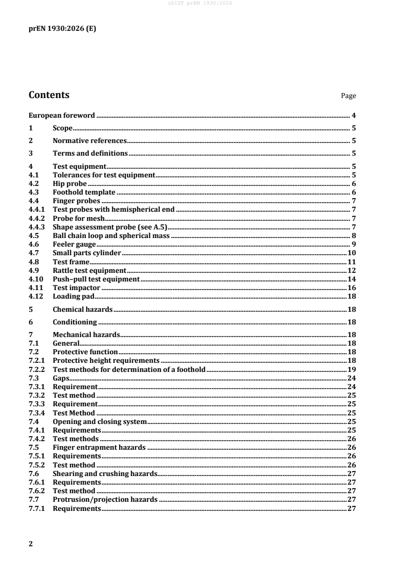
Contents Page
European foreword . 4
1 Scope . 5
2 Normative references . 5
3 Terms and definitions . 5
4 Test equipment . 5
4.1 Tolerances for test equipment . 5
4.2 Hip probe . 6
4.3 Foothold template . 6
4.4 Finger probes . 7
4.4.1 Test probes with hemispherical end . 7
4.4.2 Probe for mesh . 7
4.4.3 Shape assessment probe (see A.5) . 7
4.5 Ball chain loop and spherical mass . 8
4.6 Feeler gauge . 9
4.7 Small parts cylinder . 10
4.8 Test frame . 11
4.9 Rattle test equipment . 12
4.10 Push–pull test equipment . 14
4.11 Test impactor . 16
4.12 Loading pad . 18
5 Chemical hazards . 18
6 Conditioning . 18
7 Mechanical hazards . 18
7.1 General. 18
7.2 Protective function . 18
7.2.1 Protective height requirements . 18
7.2.2 Test methods for determination of a foothold . 19
7.3 Gaps . 24
7.3.1 Requirement . 24
7.3.2 Test method . 25
7.3.3 Requirement . 25
7.3.4 Test Method . 25
7.4 Opening and closing system . 25
7.4.1 Requirements . 25
7.4.2 Test methods . 26
7.5 Finger entrapment hazards . 26
7.5.1 Requirements . 26
7.5.2 Test method . 26
7.6 Shearing and crushing hazards. 27
7.6.1 Requirements . 27
7.6.2 Test method . 27
7.7 Protrusion/projection hazards . 27
7.7.1 Requirements . 27
7.7.2 Test method . 27
7.8 Choking and ingestion hazards. 27
7.8.1 Requirements . 27
7.8.2 Test methods . 28
7.9 Suffocation hazards . 29
7.10 Hazardous edges and points . 29
7.11 Structural integrity . 29
7.11.1 Requirements . 29
7.11.2 Requirements for connecting screws . 29
7.11.3 Requirements for staples. 29
7.11.4 Effectiveness of the fixing, locking devices and opening systems . 30
7.12 Security of the safety barrier from impact . 30
7.12.1 Requirements . 30
7.12.2 Test method . 31
8 Flammability hazards for safety barriers with fabric components . 32
9 Additional hazards . 32
9.1 Use of a tool . 32
9.2 Toys . 33
10 Product information . 33
10.1 General . 33
10.2 Marking requirements . 33
10.2.1 General . 33
10.2.2 Durability of marking . 33
10.3 Purchase information . 34
10.4 Instructions for use . 35
10.4.1 General . 35
10.4.2 Warnings . 35
10.4.3 Additional information . 35
Annex A (informative) Rationales . 37
A.1 General . 37
A.2 Chemical hazards (Clause 5). 37
A.3 Mechanical hazards (Clause 7) . 37
A.4 Flammability hazards (Clause 8) . 39
A.5 Shape assessment probe (Subclause 4.4.3) . 39
A.6 Additional hazards (Clause 9) . 39
A.7 Toys (Subclause 9.2) . 39
Annex ZA (informative) Relationship between this European Standard and the essential
requirements of Regulation 2023/988/EU aimed to be covered . 40
Bibliography . 43
European foreword
This document (prEN 1930:2026) has been prepared by Technical Committee CEN/TC 252 “Child care
articles”, the secretariat of which is held by AFNOR.
This document is currently submitted to the CEN Enquiry.
This document will supersede EN 1930:2011.
In comparison with the previous edition, the following technical modifications have been made:
— Normative references have been updated (Clause 2);
— Terms and definitions have been updated (Clause 3);
— A better description of the Finger Probe has been provided (4.4.1);
— Reference to EN 17826:2025 is made in place of the table of elements (Clause 5);
— Requirements for footholds on a rigid continuous curved structure have been added together with
corresponding figures (7.2.2.10);
— Requirements for the hip probe on flexible barriers have been introduced (7.3.3 and 7.3.4);
— The range of the closing system with a mechanism that closes the system without the intervention of
the user has been specified (7.4.1.3);
— A new test for the closing mechanism has been introduced (7.4.2.3);
— Glass is not permitted in safety barriers (7.11.1);
— Marking requirements have been updated (10.2).
This document has been prepared under a standardization request addressed to CEN by the European
Commission. The Standing Committee of the EFTA States subsequently approves these requests for its
Member States.
For the relationship with EU Legislation, see informative Annex ZA, which is an integral part of this
document.
1 Scope
This document specifies the safety requirements and test methods for child safety barriers for domestic
indoor use.
This document does not apply to products designed to be fitted across windows.
If the safety barrier has other functions not covered in this document, the relevant European Standard(s)
apply.
2 Normative references
The following documents are referred to in the text in such a way that some or all of their content
constitutes requirements of this document. For dated references, only the edition cited applies. For
undated references, the latest edition of the referenced document (including any amendments) applies.
EN 71-2:2020+A1:2025, Safety of toys — Part 2: Flammability
EN 17826:2025, Child care articles — Chemical hazards — Requirements
3 Terms and definitions
For the purposes of this document, the following terms and definitions apply.
ISO and IEC maintain terminology databases for use in standardization at the following addresses:
— ISO Online browsing platform: available at http://www.iso.org/obp/
— IEC Electropedia: available at http://www.electropedia.org/
3.1
safety barrier
barrier designed to be fitted across openings to limit a child's access inside the home and to prevent
young children up to 24 months of age passing through
3.2
opening system
system allowing access by releasing the locking device(s) and opening the safety barrier or a section of
the safety barrier or by removing the safety barrier
3.3
closing system
system restricting access by closing and activating the locking device(s), which can be operated with or
without the intervention of the user
4 Test equipment
4.1 Tolerances for test equipment
Unless otherwise stated, the tolerance of the test equipment shall be:
— Forces: ± 5 %;
— Masses: ± 0,5 %;
— Dimensions: ± 1,0 mm;
— Positioning of loading pads: ± 5 mm; and
— Duration of forces: (2 ± 1) s for durability tests; (10 ± 2) s for static load tests.
Unless otherwise specified, the test forces may be applied by any suitable device which does not
adversely affect the results.
4.2 Hip probe
A probe made from Polyoxymethylen (POM) plastic with the dimensions given in Figure 1.
Dimensions in millimetres
Key
1 longitudinal axis
Figure 1 — Hip probe
4.3 Foothold template
A strip of 10 mm thick transparent rigid material shall be cut to the shape as shown in Figure 2.
The sides of the template shall be square to the faces. All edges and corners shall be left as machined
without any radius.
Dimensions in millimetres
Key
1 triangular cells plotted on a (5 ± 0,2) mm × (5 ± 0,2) mm grid
Figure 2 — Template for foothold test (example of left-hand template)
4.4 Finger probes
4.4.1 Test probes with hemispherical end
0 0
Probes shall be made from plastic or other hard, smooth material of diameters mm, mm
5 7
( −0,1) ( −0,1)
+0,1
and 12 mm with a full hemispherical end that can be mounted on a force-measuring device, see
( )
Figure 3.
A line ascribed around the circumference shall show the maximum depth of penetration allowed, see
Figure 3.
Dimensions in millimetres
Key
Probe type 5 mm probe 7 mm probe 12 mm probe
Diameter ØA 0 0 +0,1
5 7 12
( −0,1) ( −0,1) ( )
Radius RB Half of diameter A Half of diameter A Half of diameter A
1 Line scribed around circumference showing depth of penetration
Figure 3 — Test probes with hemispherical end
4.4.2 Probe for mesh
Mesh probe shall be made from plastic or other hard, smooth material with the dimensions shown in
Figure 4.
Dimensions in millimetres
Figure 4 — Test probe for mesh
4.4.3 Shape assessment probe (see A.5)
Probe shall be made from plastic or other hard, smooth material with the dimensions shown in Figure 5.
Dimensions in millimetres
Key
A front view
B top view
C side view
D 3D view
Figure 5 — Shape assessment probe
4.5 Ball chain loop and spherical mass
This equipment comprises a ball chain loop attached to a spherical mass at a common fixing point. See
Figure 6.
The ball chain comprises 10 balls per 40 mm, equally distributed along the length of the chain when the
chain is loaded with a mass of (2,5 ± 0,05) kg.
The diameter of each ball shall be (3,2 ± 0,2) mm.
Dimensions in millimetres
Figure 6 — Ball chain
The ball chain loop is formed by the ball chain entering the spherical mass at a common fixing point with
a ball from each side of the chain in contact with each other. The external peripheral length of the ball
+5
chain loop shall be 400 mm. See Figure 7.
A smooth spherical mass of (2,5 ± 0,05) kg and a diameter of 115 mm.
Dimensions in millimetres
Key
1 ball chain loop
2 spherical mass
3 common fixing point
Figure 7 — Ball chain loop and spherical mass
4.6 Feeler gauge
The feeler gauge shall have a thickness of (0,4 ± 0,02) mm, with the end to be inserted having a radius of
approximately 3 mm. See Figure 8.
Dimensions in millimeters
Figure 8 — Feeler gauge
4.7 Small parts cylinder
The cylinder shall have the dimensions given in Figure 9.
Dimensions in millimetres
Figure 9 — Small parts cylinder
4.8 Test frame
A rigid construction shall be made from 100 mm × 100 mm steel tube, which has a vertical beam
adjustable in the horizontal direction within the frame made from 100 mm × 100 mm steel tube, see
Figure 10.
The maximum deflection of the test frame and the adjustable vertical beam shall be 1 mm when a force
of 1 000 N is applied in the positions and directions given in Figure 10. The application of the forces shall
be done in the sequence of F, F1 and F2 and the measurements taken in the sequence M, M1 and M2.
One smooth, planed beech pad on each side of the test frame of consistent thickness throughout its length
(50 ± 1) mm shall be fixed to the surface of the vertical beams to which the safety barrier is fitted.
The vertical beams and beech pads shall, once adjusted, not move or twist during the fitting and testing
of the safety barrier.
Dimensions in millimetres
Key
F force
M measurement
1 beech pads
2 adjustable beam
Figure 10 — Test frame — Front view and side view
Where the safety barrier is designed to be fitted to a tube or post (for example with a Y shape fixing, see
Figure 11), the adjustable beam and its beech pad shall be replaced by a metal tube with the maximum
diameter or maximum dimension allowed by the manufacturer in the instructions for use.
A B
Key
A Y shape fixing
B Y shape fixing in use
Figure 11 — Example of Y shape fixing on safety barrier
4.9 Rattle test equipment
The apparatus shall be as shown in Figure 12, consisting of a steel driving disc of 110 mm diameter,
+5
having a mass of 1 kg and capable of rotating at a speed of 120 RPM. The disc shall be mounted on the
−0
pivot support arm, pivoted at its base.
The disc shall be linked to the safety barrier by means of a 200 mm link arm having a mass of
(0,15 ± 0,02) kg. The link arm shall be freely pivoted on the disc. The centre of the pivot point for the link
arm shall be located (45 ± 1) mm from the centre of the disc.
The link arm shall be securely connected to the safety barrier by the use of any suitable means that allows
the arm, at the point at which it attaches to the safety barrier, to pivot e.g. a clamp with pivot attachment.
The distance between the pivot point of the support arm (4 and 7 in Figure 12) and centre of the steel
driving disc shall be (600 ± 20) mm on the arm (2 in Figure 12).
The total mass of the test equipment shall be (11 ± 1) kg with the majority of the weight positioned within
the base to prevent movement whilst in use.
Dimensions in millimetres
Key
1 driving disc
2 pivot support arm, which incorporates a drive mechanism from the motor to the driving disc
3 link arm
4 centre of rotation
5 clamp
6 base, which incorporates a drive mechanism (electric motor)
7 pivot points
8 movement of pivoting support arm
Figure 12 — Rattle test equipment
4.10 Push–pull test equipment
A rigid clamp of (100 ± 5) mm shall be used, with the width adjustable to the thickness of the top rail of
the safety barrier to which horizontal forward and backward forces are applied, see Figure 13 and
Figure 14.
Dimensions in millimetres
Key
1 rigid clamp
2 centre line indicating direction and position for the application of the force
3 negligible mass, to prevent undue damage (e.g. foam)
4 top of the barrier
Figure 13 — Clamp
Key
1 adjustable opening 4 safety barrier 7 support 10 adjustable height
2 test frame 5 clamp 8 force gauge
3 beech pads 6 force applicator 9 floor
Figure 14 — Example of push-pull test apparatus top and side view
4.11 Test impactor
The impactor (see Figure 15) shall consist of a basketball made of a synthetic material and having a
circumference of 750 mm to 780 mm inflated to a pressure of (72,5 ± 5) kPa and attached by a network
of elastic cords to the mounting ring. The ball mounting shall consist of a ring having an outside diameter
of (150 ± 5) mm and an inside diameter of (90 ± 5) mm. The rear face of this ring shall be attached to the
main body of the impactor and its front face shaped to fit the ball.
The main body of the impactor shall consist of a mass supported by cords or flexible wire of negligible
mass, (850 ± 10) mm long attached to a rigid support structure, see Figure 15.
The total mass of the impactor shall be 10 kg, excluding the support structure.
Dimensions in millimetres
Key
1 ball mounting
2 retaining device
3 basketball
4 elastic cord
5 disc mass
6 rigid support structure
Figure 15 — Test impactor
4.12 Loading pad
A square plate measuring 10 cm × 10 cm (± 0,2 cm).
5 Chemical hazards
The migration of elements from materials on exterior surfaces shall comply with EN 17826:2025, 4.2.
Textile components shall comply with EN 17826:2025, 4.4 and 4.6.
If testing is required, a separate unconditioned sample shall be used for the tests in Clause 5.
6 Conditioning
Before the following testing, removable fabrics shall be cleaned or washed and dried twice in accordance
with the manufacturer's instructions. Any resulting shrinkage shall not prevent any removable fabric
from being refitted.
Safety gates shall be stored for a least 24 hours immediately before testing at ambient conditions of 15 °C
to 27 °C.
7 Mechanical hazards
7.1 General
Unless otherwise specified, the mechanical tests shall be carried out on the same safety barrier or safety
barrier combination (e.g. with extensions to fit a wider opening) in the order listed.
Assembly instructions shall be provided prior to testing.
All requirements from 7.1 to 7.12 shall be checked and all tests shall be conducted with the safety barrier
set up for normal use in accordance with the manufacturer’s instructions and in the closed position. All
tests shall be carried out with the safety barrier positioned within the test frame specified in 4.8 and
where applicable, supported by the test frame at the bottom (see Annex A, A.1).
The tests shall be carried out in ambient conditions of 15 °C to 27 °C.
If the test is carried out in a different temperature range, the temperature shall be documented in the test
report.
The requirements and test methods do not apply to the safety barrier when it is being set up or
dismantled.
Where the safety barrier can be fitted with extensions in accordance with the manufacturer’s
instructions, the most onerous combination shall be used to determine whether the safety barrier
conforms to the requirements of this document.
7.2 Protective function
7.2.1 Protective height requirements
The safety barrier shall maintain a minimum height of 650 mm extending across the full width of the
safety barrier between two beech pads of the test frame in which there shall be no footholds when tested
in accordance with 7.2.2.
After testing in accordance with 7.2.2, the safety barrier shall still function as intended in accordance with
the manufacturer’s instructions.
The rationale for this requirement is given in A.3.1.
7.2.2 Test methods for determination of a foothold
7.2.2.1 General
Footholds shall be assessed with the safety barrier in the test frame with a vertical force of 250 N applied
centrally to the top of the safety barrier.
7.2.2.2 Continuous structure
A foothold exists on a continuous structure if four triangles marked on the template (see 4.3) are
completely obscured and in direct contact with the structure being checked. These four triangles shall
have at least one side in common with another of the triangles (see Figure 16).
Key
this shaded area denotes one triangle; four shaded areas denotes four covered triangles
Figure 16 — Examples of obscured triangles indicating a foothold on a continuous structure
7.2.2.3 Non-continuous structure
A foothold exists on a non-continuous structure if two or more triangles marked on the template (see 4.3)
are completely obscured and in direct contact with the structure being checked, between the edge of the
template and both the bold lines. The two or more triangles on each side of the template shall have at
least one side in common with each other (see Figure 17).
Key
this shaded area denotes one triangle
Figure 17 — Examples of obscured triangles on a foothold on a non-continuous structure
7.2.2.4 Wire, thin structures and similar parts
A foothold exists on a wire, thin structure and similar part if it projects across the bold lines on the
template (see 4.3), see Figure 18.
Key
1 denotes a wire, thin structure of similar part
Figure 18 — Example of a foothold on a wire, thin structure and similar part
7.2.2.5 Footholds on a continuous structure at an angle less than 55°
Using either the left-hand (see Figure 2) or right-hand template, place the template with its marked face
on any continuous structure inclined at an angle of less than 55° to the horizontal. Orientate either
template to check whether any four triangles are obscured and in direct contact indicating a foothold; see
Figure 19 for examples.
7.2.2.6 Footholds on a non-continuous structure at an angle of less than 55°
Using either the left-hand (see Figure 2) or right-hand template, place the template with its marked face
on any non-continuous structure inclined at an angle of less than 55° to the horizontal. Orientate either
template to check whether two or more triangles are obscured and in direct contact between the edges
of the template and the bold lines on the template indicating a foothold; see Figure 20 for examples.
7.2.2.7 Footholds on wire, thin structures or similar parts at an angle less than 55°
Using either the left-hand (see Figure 2) or right-hand template, place the template with its marked face
on any wire, thin structure or similar parts at an angle less than 55° to the horizontal. Check whether the
wire, thin structure or similar part has a line of contact extending between the two bold lines marked
along the template; see Figure 21 for examples.
7.2.2.8 Footholds on an intersecting or adjacent structure where the second structure
prevents slipping
Using either the left-hand (see Figure 2) or right-hand template, place the template with its marked face
on any structure, thin structure or similar parts between 55° and 80° to the horizontal where there is also
a supporting structure. Orientate either template to check whether any four triangles are obscured and
in contact indicating a foothold; see Figure 22 for examples.
7.2.2.9 Footholds on rigid components covered by flexible materials
Where flexible materials or fabrics are covering rigid components, the template is pushed against the
flexible material or fabric with a horizontal force of up to 30 N acting along the longitudinal axis of the
template. Orientate either the left-hand (see Figure 2) or the right-hand template to check whether any
four triangles are obscured and in direct contact with the rigid components indicating a foothold.
Figure 19 — Examples of footholds on a continuous structure at an angle less than 55°
Figure 20 — Examples of footholds on a non-continuous structure at an angle less than 55°
Figure 21 — Examples of footholds on wire, thin structures or similar parts at an angle less than
55°
Figure 22 — Examples of footholds on intersecting or adjacent structures where the second
structure prevents slipping
7.2.2.10 Footholds on a rigid continuous curved structure
A foothold exists on a rigid continuous curved structure if four or more triangles marked on the template
(see Figure 16) are completely obscured. The four or more triangles of the template should have at least
one side in common with each other (see Figure 16).
With a suitable measuring tool approach the structure at an angle of 55° to the horizontal, mark the first
contact point of the measuring tool with the structure (see Figure 23 a) and Figure 24 a)), then place the
measuring tool on the other side of the same structure in the same manner and mark the second contact
point (see Figure 23 b) and Figure 24 b)).
The surface to consider is the curved surface between the two marks (see Figure 23 c) and Figure 24 c)).
Using either the left or right foot template (see 4.3) in any horizontal orientation (Figure 25), check if four
or more triangles are obscured by projection on the area previously marked.
a) b) c)
Key
1 mark
2 mark
3 area to be considered
Figure 23 — Curved shape convex
a) b) c)
Key
1 mark
2 mark
3 area to be considered
Figure 24 — Curved shape concave
Figure 25 — Examples of footholds on a curved shape
NOTE If any component of the sample impairs the ability to see the obscured triangles on the template, it can
be necessary to cut or remove this component or part thereof.
7.3 Gaps
7.3.1 Requirement
When tested in accordance with 7.3.2, there shall be no gap in rigid or flexible materials within the safety
barrier or between the safety barrier and the side of the test frame or between the safety barrier and the
floor/base of the test frame that allows the hip probe to pass through from either side of the safety
barrier.
The rationale for this requirement is given in A.3.2.
7.3.2 Test method
For gaps in rigid materials, apply the hip probe, specified in 4.2, into any accessible gap in a straight
direction and parallel to the longitudinal axis of the probe gradually over 3 s up to a force of 30 N and
maintain the force for 3 s.
For gaps in flexible materials, apply the hip probe, specified in 4.2, into any accessible gap in any
maintained orientation gradually over 3 s up to a force of 30 N and maintain the force for 3 s.
7.3.3 Requirement
When tested in accordance with 7.3.4, the hip probe shall not pass through the opening between the floor
and the flexible barrier.
7.3.4 Test Method
For gaps in flexible barriers, apply a 90 N vertical upward force in the most critical position along the
bottom of the barrier using a strap of 120 mm in width. Apply the hip probe specified in 4.2 in any
maintained orientation gradually over 3 s up to a force of 30 N, into any accessible gap.
7.4 Opening and closing system
7.4.1 Requirements
7.4.1.1 Unintentional opening
The safety barrier shall conform to one of the following conditions:
— at least two consecutive actions are required to release the opening system, the operation of the
second being dependent on the first having been carried out and maintained; or
— at least two separate but simultaneous actions are required to release the opening system operating
on different principles;
Components for fitting the safety barrier into an opening that are not intended to be removed or released
for allowing access are excluded from this requirement.
The rationale for this requirement is given in A.3.3.
7.4.1.2 Closing system
After testing in accordance with 7.4.2.1, the closing system shall continue to operate as intended in
accordance with the manufacturer’s instructions.
7.4.1.3 Closing system with a mechanism that closes the system without the intervention of the
user
Closing systems with a mechanism that closes the opening system without the intervention of the user
shall also lock the opening system without the intervention of the user, throughout the whole range of
opening (from 0° and above). After testing in accordance with 7.4.2.2, a closing system with a mechanism
that closes the opening system without the intervention of the user shall continue to close and lock the
opening system without the intervention of the user.
Closing systems that close and lock without the intervention of the user shall have a means of indicating
that the opening system has either closed or remained open. The means of indication shall be either
audible or visual. The means of indication shall be explained in the instructions for use.
The rationale for this requirement is given in A.3.3.
7.4.2 Test methods
7.4.2.1 Closing systems
Operate the opening and locking system 300 times in accordance with the manufacturer’s instructions.
7.4.2.2 Closing systems with a mechanism that closes the system without the intervention of
the user
Operate the opening and closing system 10 times from the maximum opening position and 10 times from
the minimum opening position.
The closing system shall always close and lock the safety barrier from the whole range of opening (from
the closed position to the maximum opening position) without the intervention of the user. Minimum and
maximum openings may not be the most onerous condition therefore intermediate positions shall be
checked.
7.4.2.3 Mechanism that secures the moveable part of a rigid safety barrier to the static part of
the safety barrier frame
After testing in accordance with 7.4.2.4 the mechanism (e.g. hinge) shall continue to operate as intended
and not show any cracks or other signs of weakening.
7.4.2.4 Test method
Operate the opening and locking system 1 000 times in accordance with the manufacturer’s instructions,
opening the safety barrier to its maximum/ full range to stress the mechanism.
7.5 Finger entrapment hazards
7.5.1 Requirements
There shall be no accessible completely bounded openings in rigid materials between 7 mm and 12 mm
unless the depth is less than 10 mm or unless the shape assessment probe (see 4.4.3) enters 10 mm or
more when tested in accordance with 7.5.2.
There shall be no accessible openings in mesh that allow the test probe for mesh (see 4.4.2) to penetrate
up to the 7 mm diameter section when tested in accordance with 7.5.2.
The rationale for these requirements is given in A.3.4.
7.5.2 Test method
Check whether the 7 mm probe (see 4.4.1), with an applied force of up to 30 N, enters 10 mm or more
into any accessible completely bounded opening in any possible orientation.
If the 7 mm probe enters 10 mm or more, then the 12 mm probe (see 4.4.1) shall also enter 10 mm or
more with an applied force of up to 5 N. If the 7 mm probe enters 10 mm or more with an applied force
of up to 30 N but the 12 mm probe does not enter 10 mm or more with an applied force of up to 5 N, check
whether the 12 mm shape assessment probe (see 4.4.3) enters 10 mm or more with an applied force of
up to 5 N.
Check whether the test probe for mesh (see 4.4.2), with an applied force of up to 30 N, penetrates
accessible openings in mesh up to the 7 mm diameter section.
7.6 Shearing and crushing hazards
7.6.1 Requirements
Between the safety barrier and the floor and between the lowest edge of any closing section and the upper
surface of the horizontal member directly below there shall be no gaps between 5 mm and 12 mm.
Any such gap, equal to or greater than 12 mm shall not compress to less than 12 mm when tested in
accordance with 7.6.2.
After testing in accordance with 7.6.2 the safety barrier shall still function as intended in accordance with
the manufacturer’s instructions.
The rationale for this requirement is given in A.3.5.
7.6.2 Test method
Check all gaps without any load.
Gradually apply a vertical downwards force of 250 N on the centre of the top rail of the safety barrier by
usage of a loading pad (see 4.12) over a period of 5 s. Check all gaps while maintaining this force for 30 s.
7.7 Protrusion/projection hazards
7.7.1 Requirements
When tested in accordance with 7.7.2, the ball chain loop and spherical mass as specified in 4.5 shall not
be retained by any protruding part.
The rationale for this r
...