

EN 1490:2026
(Main)Building valves - Combined temperature and pressure relief valves - Tests and requirements
- Abstract
This document specifies dimensions, materials and performance requirements, including test methods, for combined temperature and pressure relief valves, of nominal sizes from DN 15 to DN 40, having working pressures from 0,3 MPa (3 bar) to 1,0 MPa (10 bar).
Combined temperature and pressure relief valves control and limit the temperature and pressure of the water contained in a hot water heater to the valves rating pressure and a temperature not exceeding 100 °C and will prevent water to steam formation when other temperature controls fail.
Combined temperature and pressure relief valves are classified having a maximum opening temperature range from 90 °C to 95 °C for class A and 75 °C to 80 °C for class B.
They are not intended to act as an expansion valve and do not control cold water flow.
Alone it does not constitute the control functions for a water heater.
A combined temperature and pressure relief valve is an independently mechanically operating device, therefore operating without an external energy source.
NOTE The use of the device specified in this document does not override the need to use controls (e.g. thermostats and cut-outs) which act directly on the power sources of water heaters (for more information, see Annex B).
- Status
- Not Published
- Publication Date
- 24-Nov-2026
- Technical Committee
- CEN/TC 164 - Water supply
- Current Stage
- 5060 - Closure of Vote - Formal Approval
- Start Date
- 24-Sep-2026
- Due Date
- 20-Aug-2027
- Completion Date
- 24-Sep-2026
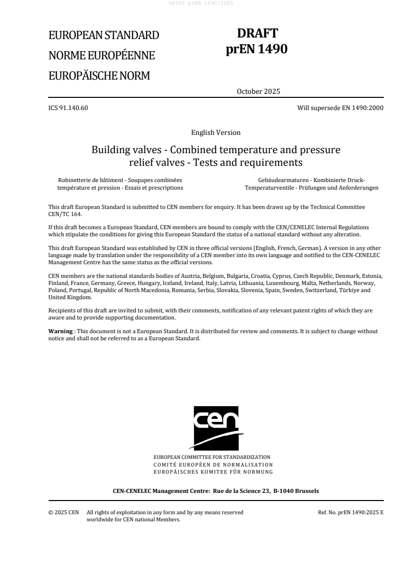

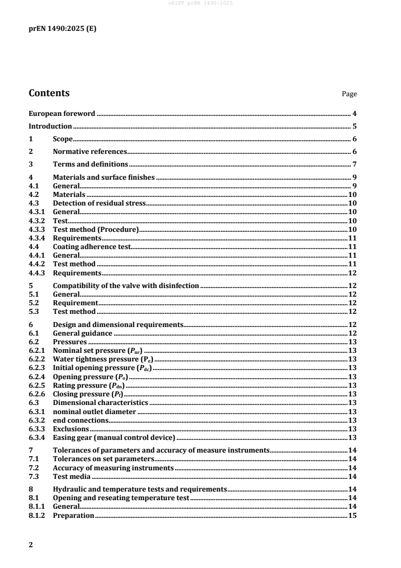
EN 1490:2026 is the CEN European Standard for building valves used as combined temperature and pressure relief valves on hot water heaters. It specifies the dimensions, materials, performance requirements and test methods for DN 15 to DN 40 devices with working pressures from 0.3 MPa to 1.0 MPa, so manufacturers, test labs and specifiers can check whether a valve will limit water temperature and pressure within the stated operating range.
What does EN 1490:2026 specify?
EN 1490:2026 specifies the requirements for combined temperature and pressure relief valves that protect hot water heaters. The valve is intended to control temperature and pressure in the heater, prevent water from reaching steam conditions if other temperature controls fail, and operate without an external energy source.
The standard covers:
- nominal sizes from DN 15 to DN 40
- working pressures from 0.3 MPa to 1.0 MPa
- two temperature classes, A and B
- devices that are not used as expansion valves and do not control cold water flow
The document is organized into clauses on scope, normative references, terms, materials and surface finishes, disinfection compatibility, design and dimensions, tolerances, hydraulic and temperature tests, mechanical tests, acoustic testing, classification, designation, nominal size, marking, and technical documents. It also has four informative annexes.
| Annex | What it covers |
|---|---|
| Annex A | Dimensional proposals and guidance on flow passages and drainage |
| Annex B | Classification of water heaters according to heating method |
| Annex C | Test rig for the disinfection test |
| Annex D | Calculation method for the nominal power rating |
What are the key requirements of EN 1490:2026?
EN 1490:2026 combines product design rules with a defined test programme. In practice, a valve has to meet material, pressure, temperature, endurance and marking requirements before it can be described and supplied as a compliant combined temperature and pressure relief valve.
Materials, coatings and water quality
Clause 4 requires the manufacturer to choose materials, but those materials and coatings must not contaminate potable water. The nature of the materials and coatings has to be stated in a technical document, and materials with limited corrosion resistance need extra protection.
This matters because the valve is in contact with drinking-water installations. The clause also requires materials to be suitable for the temperatures used in the standard’s tests, and copper alloys with zinc content above 15 % have to meet dezincification resistance requirements where that is required nationally.
Clause 4 also adds two checks for specific cases:
- brass bodies with female threads and compression ends are subject to a residual stress test based on ammonia exposure, with no cracking allowed
- coated valve housings used for corrosion protection are subject to a coating adherence test, and the coating must not scale or detach
Disinfection compatibility
Clause 5 requires the valve to remain functional after shock disinfection in a drinking water installation. The test uses one of three disinfectant solutions, and the valve has to keep working with results that stay within 10 % of the original values.
This is important for valves installed in systems that are disinfected during maintenance or after contamination events. The clause uses a test circuit with circulation, controlled pH, temperature and contact time, then checks the main opening and reseating functions again.
Design, pressure limits and dimensions
Clause 6 requires the device to be a spring-isolated type and to avoid seizing, scaling and sticking. Parts that set the valve must not be accessible to the end user without damaging the valve, and the thermal element must not place its responsive material directly in potable water.
The pressure definitions in Clause 6 are central in use:
- nominal set pressure is between 0.3 MPa and 1.0 MPa
- water tightness pressure, initial opening pressure, opening pressure, rating pressure and closing pressure are all tied to that nominal set pressure
- the nominal outlet diameter must be at least equal to the inlet size
- end connections have to be demountable and match relevant European Standards
- heat-based joints such as capillary connections are not allowed
Clause 6 also requires an easing gear for regular function checking. The manual control device has to be operable by a lift handle or rotary handle, and it must not lock the valve open when the manual force is removed.
Tests that prove opening, reseating and discharge performance
Clauses 7 and 8 define the test conditions and the hydraulic and temperature tests. Measurements have to use stated tolerances, and the usual test medium is water at a maximum of 30 °C unless otherwise specified.
The main performance tests check:
- closed and leak-tight behavior at the low end of the temperature range
- opening at the high end of the temperature range
- leak tightness at water tightness pressure
- nominal opening behavior and visible discharge
- discharge capacity at rating pressure
- closing behavior after opening
- endurance under repeated pressure and temperature cycling
Clause 8 also gives the minimum discharge rates in tables for each DN and nominal set pressure. In practice, this is what ties the valve size to the heater power it can protect.
Mechanical strength, acoustic testing and marking
Clause 9 checks the body and the easing gear under back pressure, internal pressure, bending moment and manual operating loads. The valve body must not leak, deform permanently or fracture, and the easing gear must survive repeated handling.
Clause 10 states that devices are not subject to acoustic testing. Clause 11 classifies devices by discharged capacity and nominal power rating, while Clauses 12 to 15 define designation, nominal size, marking and delivery documentation.
What terms does EN 1490:2026 define?
- Combined temperature and pressure relief valve - a valve that performs both temperature relief and pressure relief for a hot water heater.
- Nominal set pressure (Pnr) - the pressure set on production, often called the set pressure.
- Water tightness pressure (Pe) - the pressure up to which the device remains closed and leak-tight.
- Initial opening pressure (Pdc) - the pressure at which the first droplet appears after storage, showing the valve has started to open.
- Opening pressure (Po) - the pressure at which water first appears at the outlet and the valve opens.
- Rating pressure (Pdn) - the pressure at which the discharged flow exceeds the limit defined in the discharge table.
- Closing pressure (Pf) - the pressure at which the valve closes again after reaching rating pressure.
- Thermal element - the thermal probe and associated control rods that provide temperature control.
- Air break to drain - a vertical separation or air gap that prevents unwanted connection between the outlet and atmospheric drain overflow.
Who uses EN 1490:2026?
EN 1490:2026 is used by manufacturers of building valves, hot water heater makers, test laboratories, and conformity assessment teams. It is also used by installers, specifiers, quality managers and buyers who need to match a safety valve to a heater’s pressure, temperature class, nominal size and power rating.
In practice, these users rely on the standard to:
- select the correct valve for a heater
- verify test results for opening, reseating, discharge and endurance
- check marking and documentation before delivery or installation
- choose compatible end connections and materials for potable water systems
What changed in EN 1490:2026 from the previous edition?
EN 1490:2026 supersedes EN 1490:2000. The foreword lists these significant technical changes:
- the materials clause was completely revised
- class A and class B temperature ranges were introduced
- the steam test was deleted
- dimensional requirements were moved to an informative annex
- disinfection testing was introduced
- a torque test was added
- pressure relief valve testing was changed and optimized
- the coating test procedure was revised
- normative references were updated
- editorial changes were made throughout the document
Which standards are used with EN 1490:2026?
| Standard | What it contributes |
|---|---|
| EN 806 (all parts) | Rules for installations inside buildings conveying water for human consumption |
| EN 1254-2 | Requirements for compression fittings on copper tubes |
| EN 1717 | Protection against pollution and backflow prevention in potable water installations |
| EN 10226-1 | Dimensions, tolerances and designation for taper external and parallel internal pipe threads |
| EN ISO 228-1 | Dimensions, tolerances and designation for pipe threads without pressure-tight joints on the threads |
| EN ISO 6509 (all parts) | Test method for dezincification resistance of copper alloys with zinc |
| ISO 6957 | Ammonia test for stress corrosion resistance of copper alloys |
| EN 14597 | Definitions used for TR, TB and STB temperature control and cut-out devices in Annex B |
| EN 1487, EN 1488, EN 1489, EN 1491 | Companion building-valve standards for the other safety devices named in Annex B and the bibliography |
What does the EN 1490:2026 document contain?
EN 1490:2026 contains the material rules, design rules, pressure relationships and test methods needed to assess a combined temperature and pressure relief valve. It also contains the discharge-capacity tables and the power-rating table that link DN and nominal set pressure to the valve’s protection capability.
The document includes examples and supporting figures for the test arrangement, the coating-cut test, the valve layout and the disinfection rig. Annex D adds a calculation method, including a worked example, for nominal power rating.
Relations
- Effective Date
- 28-Jan-2026
- Effective Date
- 28-Jan-2026
- Effective Date
- 28-Jan-2026
- Effective Date
- 28-Jan-2026
- Effective Date
- 28-Jan-2026
- Effective Date
- 18-Dec-2024
Get Certified
Connect with accredited certification bodies for this standard

DIBt (Deutsches Institut für Bautechnik)
German Institute for Building Technology.
DIN CERTCO
DIN Group product certification.

Aboma Certification B.V.
Specialized in construction, metal, and transport sectors.
Sponsored listings
Frequently Asked Questions
EN 1490:2026 is a draft published by the European Committee for Standardization (CEN). Its full title is "Building valves - Combined temperature and pressure relief valves - Tests and requirements". This standard covers: This document specifies dimensions, materials and performance requirements, including test methods, for combined temperature and pressure relief valves, of nominal sizes from DN 15 to DN 40, having working pressures from 0,3 MPa (3 bar) to 1,0 MPa (10 bar). Combined temperature and pressure relief valves control and limit the temperature and pressure of the water contained in a hot water heater to the valves rating pressure and a temperature not exceeding 100 °C and will prevent water to steam formation when other temperature controls fail. Combined temperature and pressure relief valves are classified having a maximum opening temperature range from 90 °C to 95 °C for class A and 75 °C to 80 °C for class B. They are not intended to act as an expansion valve and do not control cold water flow. Alone it does not constitute the control functions for a water heater. A combined temperature and pressure relief valve is an independently mechanically operating device, therefore operating without an external energy source. NOTE The use of the device specified in this document does not override the need to use controls (e.g. thermostats and cut-outs) which act directly on the power sources of water heaters (for more information, see Annex B).
This document specifies dimensions, materials and performance requirements, including test methods, for combined temperature and pressure relief valves, of nominal sizes from DN 15 to DN 40, having working pressures from 0,3 MPa (3 bar) to 1,0 MPa (10 bar). Combined temperature and pressure relief valves control and limit the temperature and pressure of the water contained in a hot water heater to the valves rating pressure and a temperature not exceeding 100 °C and will prevent water to steam formation when other temperature controls fail. Combined temperature and pressure relief valves are classified having a maximum opening temperature range from 90 °C to 95 °C for class A and 75 °C to 80 °C for class B. They are not intended to act as an expansion valve and do not control cold water flow. Alone it does not constitute the control functions for a water heater. A combined temperature and pressure relief valve is an independently mechanically operating device, therefore operating without an external energy source. NOTE The use of the device specified in this document does not override the need to use controls (e.g. thermostats and cut-outs) which act directly on the power sources of water heaters (for more information, see Annex B).
EN 1490:2026 is classified under the following ICS (International Classification for Standards) categories: 91.140.60 - Water supply systems. The ICS classification helps identify the subject area and facilitates finding related standards.
EN 1490:2026 has the following relationships with other standards: It is inter standard links to EN ISO 15614-9:2025, EN ISO 15614-13:2023, EN ISO 15614-11:2025, EN ISO 15614-5:2024, EN ISO 15614-2:2025, EN 1490:2000. Understanding these relationships helps ensure you are using the most current and applicable version of the standard.
EN 1490:2026 is associated with the following European legislation: EU Directives/Regulations: 305/2011. When a standard is cited in the Official Journal of the European Union, products manufactured in conformity with it benefit from a presumption of conformity with the essential requirements of the corresponding EU directive or regulation.
EN 1490:2026 is available in PDF format for immediate download after purchase. The document can be added to your cart and obtained through the secure checkout process. Digital delivery ensures instant access to the complete standard document.
Standards Content (Sample)
SLOVENSKI STANDARD
oSIST prEN 1490:2025
01-december-2025
Ventili v stavbah - Kombinirani temperaturno tlačni razbremenilni ventili - Preskusi
in zahteve
Building valves - Combined temperature and pressure relief valves - Tests and
requirements
Gebäudearmaturen - Kombinierte Druck-Temperaturventile - Prüfungen und
Anforderungen
Robinetterie de bâtiment - Soupapes combinées température et pression - Essais et
prescriptions
Ta slovenski standard je istoveten z: prEN 1490
ICS:
91.140.60 Sistemi za oskrbo z vodo Water supply systems
oSIST prEN 1490:2025 en,fr,de
2003-01.Slovenski inštitut za standardizacijo. Razmnoževanje celote ali delov tega standarda ni dovoljeno.
oSIST prEN 1490:2025
oSIST prEN 1490:2025
DRAFT
EUROPEAN STANDARD
prEN 1490
NORME EUROPÉENNE
EUROPÄISCHE NORM
October 2025
ICS 91.140.60 Will supersede EN 1490:2000
English Version
Building valves - Combined temperature and pressure
relief valves - Tests and requirements
Robinetterie de bâtiment - Soupapes combinées Gebäudearmaturen - Kombinierte Druck-
température et pression - Essais et prescriptions Temperaturventile - Prüfungen und Anforderungen
This draft European Standard is submitted to CEN members for enquiry. It has been drawn up by the Technical Committee
CEN/TC 164.
If this draft becomes a European Standard, CEN members are bound to comply with the CEN/CENELEC Internal Regulations
which stipulate the conditions for giving this European Standard the status of a national standard without any alteration.
This draft European Standard was established by CEN in three official versions (English, French, German). A version in any other
language made by translation under the responsibility of a CEN member into its own language and notified to the CEN-CENELEC
Management Centre has the same status as the official versions.
CEN members are the national standards bodies of Austria, Belgium, Bulgaria, Croatia, Cyprus, Czech Republic, Denmark, Estonia,
Finland, France, Germany, Greece, Hungary, Iceland, Ireland, Italy, Latvia, Lithuania, Luxembourg, Malta, Netherlands, Norway,
Poland, Portugal, Republic of North Macedonia, Romania, Serbia, Slovakia, Slovenia, Spain, Sweden, Switzerland, Türkiye and
United Kingdom.
Recipients of this draft are invited to submit, with their comments, notification of any relevant patent rights of which they are
aware and to provide supporting documentation.
Warning : This document is not a European Standard. It is distributed for review and comments. It is subject to change without
notice and shall not be referred to as a European Standard.
EUROPEAN COMMITTEE FOR STANDARDIZATION
COMITÉ EUROPÉEN DE NORMALISATION
EUROPÄISCHES KOMITEE FÜR NORMUNG
CEN-CENELEC Management Centre: Rue de la Science 23, B-1040 Brussels
© 2025 CEN All rights of exploitation in any form and by any means reserved Ref. No. prEN 1490:2025 E
worldwide for CEN national Members.
oSIST prEN 1490:2025
prEN 1490:2025 (E)
Contents Page
European foreword . 4
Introduction . 5
1 Scope . 6
2 Normative references . 6
3 Terms and definitions . 7
4 Materials and surface finishes . 9
4.1 General. 9
4.2 Materials . 10
4.3 Detection of residual stress . 10
4.3.1 General. 10
4.3.2 Test . 10
4.3.3 Test method (Procedure) . 10
4.3.4 Requirements . 11
4.4 Coating adherence test. 11
4.4.1 General. 11
4.4.2 Test method . 11
4.4.3 Requirements . 12
5 Compatibility of the valve with disinfection . 12
5.1 General. 12
5.2 Requirement . 12
5.3 Test method . 12
6 Design and dimensional requirements. 12
6.1 General guidance . 12
6.2 Pressures . 13
6.2.1 Nominal set pressure (P ) . 13
nr
6.2.2 Water tightness pressure (P ) . 13
e
6.2.3 Initial opening pressure (P ) . 13
dc
6.2.4 Opening pressure (P ) . 13
o
6.2.5 Rating pressure (P ) . 13
dn
6.2.6 Closing pressure (P ) . 13
f
6.3 Dimensional characteristics . 13
6.3.1 nominal outlet diameter . 13
6.3.2 end connections . 13
6.3.3 Exclusions . 13
6.3.4 Easing gear (manual control device) . 13
7 Tolerances of parameters and accuracy of measure instruments . 14
7.1 Tolerances on set parameters . 14
7.2 Accuracy of measuring instruments . 14
7.3 Test media . 14
8 Hydraulic and temperature tests and requirements . 14
8.1 Opening and reseating temperature test . 14
8.1.1 General. 14
8.1.2 Preparation . 15
oSIST prEN 1490:2025
prEN 1490:2025 (E)
8.1.3 Verification that the device is closed . 15
8.1.4 Opening temperature (t ) . 16
o
8.1.5 Closing temperature (t ) . 16
f
8.2 Water tightness test, opening and reseating pressure test, and pressure of nominal
flow test . 16
8.2.1 Water tightness pressure (P ) . 16
e
8.2.2 Nominal opening pressure (P ) . 17
o
8.2.3 Rating pressure (P ) . 17
dn
8.2.4 Closing pressure (Pf) . 17
8.3 Water discharge test . 18
8.3.1 Procedure . 18
8.3.2 Requirement . 18
8.4 Endurance test . 18
8.4.1 Test 1 (pressure) . 18
8.4.2 Requirement . 19
8.4.3 Test 2 (temperature) . 19
8.4.4 Requirement . 19
9 Mechanical tests and requirements . 19
9.1 Mechanical strength . 19
9.1.1 Back pressure test . 19
9.1.2 Body strength test . 19
9.1.3 Bending moment test of the body of the device . 19
9.2 Mechanical strength test of the easing gear (manual control device) . 20
9.2.1 Procedure . 20
9.2.2 Requirement . 20
9.3 Operation of the easing gear. 20
9.3.1 Procedure . 20
9.3.2 Requirement . 20
9.4 Easing gear endurance test . 20
9.4.1 Procedure . 20
9.4.2 Requirement . 20
10 Acoustic tests and requirements . 20
11 Classification . 21
12 Designation . 21
13 Nominal size . 21
14 Marking . 21
15 Technical documents and presentation at delivery . 22
Annex A (informative) Dimensional proposals . 23
Annex B (informative) Classification of water heaters according to heating method . 26
Annex C (informative) Test rig: Chapter 5: Disinfection // Guidance Document WG 14 . 28
Annex D (informative) Calculation method for the nominal power rating . 29
Bibliography . 30
oSIST prEN 1490:2025
prEN 1490:2025 (E)
European foreword
This document (prEN 1490:2025) has been prepared by Technical Committee CEN/TC 164 “Water
supply”, the secretariat of which is held by AFNOR.
This document is currently submitted to the CEN Enquiry.
This document will supersede EN 1490:2000.
This document includes the following significant technical changes with respect to EN 1490:2000:
— the clause on materials was completely revised;
— class A and class B for the temperature range were introduced;
— steam test was deleted;
— dimensional requirements were moved to an informative annex;
— testing with disinfectant was introduced;
— torque test was added;
— testing of the pressure relief valve was changed and optimized;
— coating test procedure was revised;
— normative references were updated;
— editorial changes have been made throughout the entire document.
oSIST prEN 1490:2025
prEN 1490:2025 (E)
Introduction
With regard to the potential adverse effect on the quality of water intended for human consumption,
caused by the product covered by this document:
a) This document provides no information as to whether the product may be used without restriction
in any of the Member States of the EU or EFTA.
b) It should be noted that, whilst awaiting the adoption of verifiable European criteria, existing national
regulations concerning the use and or the characteristics of this product remain in force.
oSIST prEN 1490:2025
prEN 1490:2025 (E)
1 Scope
This document specifies dimensions, materials and performance requirements, including test methods,
for combined temperature and pressure relief valves, of nominal sizes from DN 15 to DN 40, having
working pressures ) from 0,3 MPa (3 bar) to 1,0 MPa (10 bar).
Combined temperature and pressure relief valves control and limit the temperature and pressure of the
water contained in a hot water heater to the valves rating pressure and a temperature not exceeding
100 °C and will prevent water to steam formation when other temperature controls fail.
Combined temperature and pressure relief valves are classified having a maximum opening temperature
range from 90 °C to 95 °C for class A and 75 °C to 80 °C for class B.
They are not intended to act as an expansion valve and do not control cold water flow.
Alone it does not constitute the control functions for a water heater.
A combined temperature and pressure relief valve is an independently mechanically operating device,
therefore operating without an external energy source.
NOTE The use of the device specified in this document does not override the need to use controls (e.g.
thermostats and cut-outs) which act directly on the power sources of water heaters (for more information, see
Annex B).
2 Normative references
The following documents are referred to in the text in such a way that some or all of their content
constitutes requirements of this document. For dated references, only the edition cited applies. For
undated references, the latest edition of the referenced document (including any amendments) applies.
EN 806 (all parts), Specifications for installations inside buildings conveying water for human consumption
EN 1254-2, Copper and copper alloys — Plumbing fittings — Part 2: Compression fittings for use with
copper tubes
EN 1717, Protection against pollution of water intended for human consumption in potable water
installations and general requirements for devices to prevent pollution by backflow
EN 10226-1, Pipe threads where pressure tight joints are made on the threads — Part 1: Taper external
threads and parallel internal threads — Dimensions, tolerances and designation
EN ISO 228-1, Pipe threads where pressure-tight joints are not made on the threads — Part 1: Dimensions,
tolerances and designation (ISO 228-1)
EN ISO 6509 (all parts), Corrosion of metals and alloys — Determination of dezincification resistance of
copper alloys with zinc (ISO 6509 (all parts))
All pressures are gauge unless otherwise stated.
oSIST prEN 1490:2025
prEN 1490:2025 (E)
3 Terms and definitions
For the purposes of this document, the following terms and definitions apply.
ISO and IEC maintain terminology databases for use in standardization at the following addresses:
— ISO Online browsing platform: available at https://www.iso.org/obp/
— IEC Electropedia: available at https://www.electropedia.org/
3.1
temperature relief valve
temperature activated valve which opens automatically at a specified set temperature to discharge fluid
Note 1 to entry: It is fitted to water heaters to prevent the temperature of the contained water from exceeding
100 °C.
3.2
pressure relief valve
pressure activated valve which opens automatically at a specified set pressure to discharge fluid
Note 1 to entry: It is fitted to prevent the pressure in a water heater from exceeding the nominal set pressure.
3.3
combined temperature and pressure relief valve
valve which is capable of performing the function of both a temperature relief valve and a pressure relief
valve
Note 1 to entry: For the purposes of this document, the combined temperature and pressure relief valve is hereafter
referred to as ‘the device’.
3.4
thermal element
thermal probe and associated control rods that provide the thermal control
3.5
air break to drain
vertical distance realized by air inlets or full disconnection between the lowest point of the outlet and the
spill over level of the atmospheric drain overflow
3.6
nominal set pressure
P
nr
pressure of the device which is set on production
Note 1 to entry: The “nominal set pressure” (Pnr) is often called “set pressure”.
Note 2 to entry: See Figure 1.
oSIST prEN 1490:2025
prEN 1490:2025 (E)
Key
X time
Y pressure
Figure 1 — Pressures
3.7
water tightness pressure
P
e
pressure up to which the device is closed
Note 1 to entry: See Figure 1.
3.8
initial opening pressure
P
dc
pressure at which the device opens for the first time, as indicated by the first droplet of water at the outlet
of the device, after a period of storage
Note 1 to entry: See Figure 1.
3.9
opening pressure
P
o
pressure at which the device opens as indicated by the appearance of water at the outlet of the device
Note 1 to entry: See Figure 1.
3.10
rating pressure
P
dn
pressure at which the discharged flow is above the limit given in Table 2
Note 1 to entry: See Figure 1 and Table 2.
oSIST prEN 1490:2025
prEN 1490:2025 (E)
3.11
closing pressure
P
f
pressure at which the device closes after having reached the rating pressure
Note 1 to entry: See Figure 1.
3.12
maximum working temperature
tmax
maximum temperature at which the device is designed to be used (100 °C)
3.13
nominal set temperature class A
nominal set temperature class B
t
nr
temperature range at which the device is set on production
Note 1 to entry: For class A, the range is 90 °C to 95 °C. For class B, the range is 75 °C to 80 °C.
3.14
initial opening temperature
t
dc
temperature at which the device opens, as indicated by the first droplet of water, after a period of storage
3.15
opening temperature
t
o
temperature at which the device opens, as indicated by the appearance of water at the outlet of the device
3.16
closing temperature
t
f
temperature at which the device closes after discharging under temperature conditions
3.17
water discharge capacity
rate of water discharge, l/h, that can be discharged through the device under the conditions specified in
the test in 8.2
3.18
nominal power rating
power rating, in Table 5, to be assigned to a device
4 Materials and surface finishes
4.1 General
The selection of materials is the responsibility of the manufacturer, provided they satisfy the following
requirements:
a) materials and coatings shall not contaminate the potable water;
b) the nature of the materials and coatings used shall be stated in a technical document;
oSIST prEN 1490:2025
prEN 1490:2025 (E)
c) materials with insufficient corrosion resistance (e.g. cast iron, aluminium) shall have additional
protection;
d) the materials used shall be suitable for the temperatures specified in the tests in this document;
e) the materials, and in particular copper alloys, for which recommendations or
European/International standards exist, shall comply with the relevant recommendations or
European/International standards.
4.2 Materials
All materials coming into contact with water intended for human consumption shall present no health
risk nor cause any change to the water in terms of quality, appearance, smell or taste.
NOTE It is pointed out that whilst awaiting the adoption of verifiable European criteria for testing materials in
contact with water intended for human consumption, existing national regulations concerning the use and/or the
characteristics of these products remain in force.
Copper-zinc alloys containing more than 15 % zinc are subject to dezincification when submitted to
water capable of dezincification. In the countries where the use of products made of dezincification
resistant materials is required, the materials used shall guarantee a dezincification depth less than
200 μm in any direction. For this purpose, materials shall be tested in accordance with
EN ISO 6509 (all parts) and the product shall be marked in compliance with the indications according to
Clause 14.
4.3 Detection of residual stress
4.3.1 General
This test shall be performed for bodies made out of brass materials and with female threads according to
EN 10226-1 and compression ends according to EN 1254-2.
4.3.2 Test
This test is based on ISO 6957. Its purpose is to verify the resistance to cracking under stress corrosion
in ammonia medium (as described in 4.3.3 b).
The test entails exposing test specimens consisting of the assembled device in an atmosphere loaded with
ammonia vapour.
4.3.3 Test method (Procedure)
The paragraph below details ISO 6957.
Test solution:
a) Use solutions of analysis quality and of distilled water.
b) Solution of ammonia at 20 % (in weight).
c) The pH of the test solution shall be adjusted to 9,5 by using hydrochloric acid.
d) The test temperature shall be (23 ± 2) °C with a measurement uncertainty of ±1 K.
Test specimen:
e) The test specimen consists of three samples of a single assembled product. The test specimen shall
be inserted into the test enclosure under no stress.
oSIST prEN 1490:2025
prEN 1490:2025 (E)
Instructions:
f) Rinse the test specimens with a clean non-chlorinated solvent (e.g. ethanol).
g) Let it dry in the air.
h) Insert the test specimens into the test enclosure along with the ammonia solution. The volume of the
container made of glass (e.g. desiccator) shall be minimum (10 ± 1) l.
i) The volume of the solution inserted shall be (200 ± 10) ml per 3 l of total volume of the container
(e.g. for a 10 l container it means (667 ± 33)
...